

Page 1

GRANITE 1300 SERIES
COMBINATION LATHE/MILL/DRILL
OPERATOR’S MANUAL
Updated April, 2008
170 Aprill Dr., Ann Arbor, MI, USA 48103
Toll Free 1-800-476-4849
www.smithy.com
Page 2

© 2008 Smithy Co. All rights reserved (Revision 3).
170 Aprill Dr., Ann Arbor, Michigan, USA 48103
Toll Free Hotline: 1-800-476-4849
Fax: 1-800-431-8892
International: 734-913-6700
International Fax: 734-913-6663
All images shown are from Granite Classic 1324 model.
All other images for other Granite models are specified.
All rights reserved. No part of this manual may be reproduced or transmitted in any form
by any means, electronic, mechanical, photocopying, recording, or otherwise,
without prior written permission of Smithy Co. For information on getting permission for
reprints and excerpts, comments, or suggestions, contact info@smithy.com
While every precaution has been taken in the preparation of this manual, Smithy Co. shall not
have any liability to any person or entity with respect to any loss or damage caused or
alleged to be caused directly or indirectly by the instructions contained in this manual.
Please see section on warranty and safety precautions before operating the machine.
Printed and bound in the United States of America.
Page 3

Table of Contents
Chapter 1: Introduction
Welcome . . . . . . . . . . . . . . . . . . . . . . . . . . . . . . . . . . . . . . . . . . . . . . . . .1-1
Contact Information and Customer Information . . . . . . . . . . . . . . . .1-2
Chapter 2: Safety
Overview . . . . . . . . . . . . . . . . . . . . . . . . . . . . . . . . . . . . . . . . . . . . . . . . .2-1
Symbols Used in this Manual . . . . . . . . . . . . . . . . . . . . . . . . . . . . . . .2-1
Shop Safety Rules . . . . . . . . . . . . . . . . . . . . . . . . . . . . . . . . . . . . . . . . .2-2
Machine Safety Rules . . . . . . . . . . . . . . . . . . . . . . . . . . . . . . . . . . . . . .2-3
Chapter 3: Inventory Check List
Overview . . . . . . . . . . . . . . . . . . . . . . . . . . . . . . . . . . . . . . . . . . . . . . . . .3-1
Items Mounted to your machine . . . . . . . . . . . . . . . . . . . . . . . . . . . . .3-1
Items Packed in the larger Smithy Box . . . . . . . . . . . . . . . . . . . . . . .3-2
Items Packed in smaller Smity Box
. . . . . . . . . . . . . . . . . . . . . . . . . .3-4
Items Packed in Plastic Bag . . . . . . . . . . . . . . . . . . . . . . . . . . . . . . . .3-5
Additional Items for GN-IMX Series . . . . . . . . . . . . . . . . . . . . . . . . . .3-5
Chapter 4: Machine Overview
Overview . . . . . . . . . . . . . . . . . . . . . . . . . . . . . . . . . . . . . . . . . . . . . . . . .4-1
Major Features Identified . . . . . . . . . . . . . . . . . . . . . . . . . . . . . . . . . . .4-1
Millhead Components and Functions . . . . . . . . . . . . . . . . . . . . . . . . .4-3
Powerhead Components and Functions . . . . . . . . . . . . . . . . . . . . . .4-5
Pulley Box . . . . . . . . . . . . . . . . . . . . . . . . . . . . . . . . . . . . . . . . . . . . . . . .4-7
Carriage Asssembly . . . . . . . . . . . . . . . . . . . . . . . . . . . . . . . . . . . . . . .4-8
Carriage Assembly - Compound Angle Toolpost . . . . . . . . . . . . . .4-11
Tailstock . . . . . . . . . . . . . . . . . . . . . . . . . . . . . . . . . . . . . . . . . . . . . . . .4-12
For Granite MAX and IMX Series Machine . . . . . . . . . . . . . . . . . .4-13
Chapter 5: Preparing Your Machine For Operation
Overview . . . . . . . . . . . . . . . . . . . . . . . . . . . . . . . . . . . . . . . . . . . . . . . . .5-1
Assembly of Minor Components
. . . . . . . . . . . . . . . . . . . . . . . . . . . . .
5-1
Drill Chuck and Arbor . . . . . . . . . . . . . . . . . . . . . . . . . . . . . . . . . . . . . .
5-1
Arbor Plug . . . . . . . . . . . . . . . . . . . . . . . . . . . . . . . . . . . . . . . . . . . . . . . .5-2
Mill Spindle Cover . . . . . . . . . . . . . . . . . . . . . . . . . . . . . . . . . . . . . . . . .5-2
Cleaning and Lubricating Your Machine . . . . . . . . . . . . . . . . . . . . . .5-3
Lubrication Schedule
. . . . . . . . . . . . . . . . . . . . . . . . . . . . . . . . . . . . . .5-3
Lubrication Points . . . . . . . . . . . . . . . . . . . . . . . . . . . . . . . . . . . . . . . . .5-3
Gearbox . . . . . . . . . . . . . . . . . . . . . . . . . . . . . . . . . . . . . . . . . . . . . . . . . .5-4
Page 4

Ways . . . . . . . . . . . . . . . . . . . . . . . . . . . . . . . . . . . . . . . . . . . . . . . . . . . .5-5
Carriage Assembly - Saddle . . . . . . . . . . . . . . . . . . . . . . . . . . . . . . . .5-5
Carriage Assembly - Cross-Slide Table . . . . . . . . . . . . . . . . . . . . . . .5-6
Compound Angle Toolpost . . . . . . . . . . . . . . . . . . . . . . . . . . . . . . . . . .5-6
Cross-Slide Screw . . . . . . . . . . . . . . . . . . . . . . . . . . . . . . . . . . . . . . . . .5-6
Leadscrew . . . . . . . . . . . . . . . . . . . . . . . . . . . . . . . . . . . . . . . . . . . . . . . .5-7
Oil Drip . . . . . . . . . . . . . . . . . . . . . . . . . . . . . . . . . . . . . . . . . . . . . . . . . . .5-7
Quick Change Gearbox . . . . . . . . . . . . . . . . . . . . . . . . . . . . . . . . . . . . .5-7
Tailstock Barrel . . . . . . . . . . . . . . . . . . . . . . . . . . . . . . . . . . . . . . . . . . .5-8
Mill/Drill Clutch . . . . . . . . . . . . . . . . . . . . . . . . . . . . . . . . . . . . . . . . . . . .5-8
Adjusting Gibs . . . . . . . . . . . . . . . . . . . . . . . . . . . . . . . . . . . . . . . . . . . .5-9
Carriage Assembly - Saddle . . . . . . . . . . . . . . . . . . . . . . . . . . . . . . . .5-9
Carriage Assembly - Cross-Slide Table . . . . . . . . . . . . . . . . . . . . . .5-10
Compound Angle Toolpost . . . . . . . . . . . . . . . . . . . . . . . . . . . . . . . . .5-11
Tailstock . . . . . . . . . . . . . . . . . . . . . . . . . . . . . . . . . . . . . . . . . . . . . . . .5-12
Adjusting Backlash . . . . . . . . . . . . . . . . . . . . . . . . . . . . . . . . . . . . . . .5-13
Cross-Slide Screw . . . . . . . . . . . . . . . . . . . . . . . . . . . . . . . . . . . . . . . .5-13
Cross-Slide Screw to the Front Screw Mount . . . . . . . . . . . . . . . .5-13
Cross-Slide Screw to Brass Nut and Nut to the Saddle . . . . . . . .5-14
Longitudinal Leadscrew . . . . . . . . . . . . . . . . . . . . . . . . . . . . . . . . . . .5-15
Half-Nut to Leadscrew Backlash . . . . . . . . . . . . . . . . . . . . . . . . . . .5-16
Mill Feed Backlash . . . . . . . . . . . . . . . . . . . . . . . . . . . . . . . . . . . . . . .
5-16
Adjusting the fit between the Worm Gear
and Pinion Gear Shaft . . . . . . . . . . . . . . . . . . . . . . . . . . . . . . . . . . . . .5-16
Adjusting the fit of the Quill Gear to the Quill Rack . . . . . . . . . . . .5-17
Adjusting Drive Belt Tension . . . . . . . . . . . . . . . . . . . . . . . . . . . . . . .5-19
Adjusting Millhead Belt Tension . . . . . . . . . . . . . . . . . . . . . . . . . . . .5-19
Adjusting Lathe Belt Tension . . . . . . . . . . . . . . . . . . . . . . . . . . . . . . .5-19
Becoming Familiar with Operating Your Smithy Granite . . . . . . .5-20
Running in the Lathe . . . . . . . . . . . . . . . . . . . . . . . . . . . . . . . . . . . . . .5-21
Running in the Mill/Drill . . . . . . . . . . . . . . . . . . . . . . . . . . . . . . . . . . .5-22
Chapter 6: Tooling Installation
Overview . . . . . . . . . . . . . . . . . . . . . . . . . . . . . . . . . . . . . . . . . . . . . . . . .6-1
Setting-up Lathe Turning
. . . . . . . . . . . . . . . . . . . . . . . . . . . . . . . . . . .6-1
Lathe Spindle . . . . . . . . . . . . . . . . . . . . . . . . . . . . . . . . . . . . . . . . . . . . .6-1
Removing D1-4 Camlock Tooling from the Lathe Spindle . . . . . . . .6-2
Installing D1-4 Camlock Tooling . . . . . . . . . . . . . . . . . . . . . . . . . . . . .6-2
Installing Tailstock . . . . . . . . . . . . . . . . . . . . . . . . . . . . . . . . . . . . . . . . .6-3
Installing Compond Angle Toolpost . . . . . . . . . . . . . . . . . . . . . . . . . .6-3
Installing Tooling into the Compound Angle Toolpost . . . . . . . . . .
6-3
Setting-up Tooling in the Mill/Drill Spindle . . . . . . . . . . . . . . . . . . . .6-4
Aligning Tooling . . . . . . . . . . . . . . . . . . . . . . . . . . . . . . . . . . . . . . . . . . .6-4
Installing R-8 Tooling with the Drawbar . . . . . . . . . . . . . . . . . . . . . .6-4
Removing R-8 Tooling from the Drawbar . . . . . . . . . . . . . . . . . . . . .6-5
Page 5

Chapter 7: Manual Operations
Overview . . . . . . . . . . . . . . . . . . . . . . . . . . . . . . . . . . . . . . . . . . . . . . . . .7-1
Changing Between Lathe and Mill Operation . . . . . . . . . . . . . . . . . .7-1
Manual Feeding . . . . . . . . . . . . . . . . . . . . . . . . . . . . . . . . . . . . . . . . . . .7-2
Mill/Drill Spindle . . . . . . . . . . . . . . . . . . . . . . . . . . . . . . . . . . . . . . . . . . .7-2
Coarse Feed Operation . . . . . . . . . . . . . . . . . . . . . . . . . . . . . . . . . . . . .7-3
Fine Feed Operation . . . . . . . . . . . . . . . . . . . . . . . . . . . . . . . . . . . . . . .7-3
Cross-Slide Table and Carriage Assembly . . . . . . . . . . . . . . . . . . . .7-3
Cross-Slide Table . . . . . . . . . . . . . . . . . . . . . . . . . . . . . . . . . . . . . . . . . .7-3
Carriage Assembly . . . . . . . . . . . . . . . . . . . . . . . . . . . . . . . . . . . . . . . .7-4
Chapter 8: Speeds and Feeds
Overview . . . . . . . . . . . . . . . . . . . . . . . . . . . . . . . . . . . . . . . . . . . . . . . . .8-1
Speed and Feed Rates Defined . . . . . . . . . . . . . . . . . . . . . . . . . . . . . .8-1
Setting the Spindle Rotational Speed . . . . . . . . . . . . . . . . . . . . . . . .8-2
High Range Speed Set-up . . . . . . . . . . . . . . . . . . . . . . . . . . . . . . . . . .8-3
Mid Range Speed Set-up . . . . . . . . . . . . . . . . . . . . . . . . . . . . . . . . . . .8-3
Low Range Speed Set-up . . . . . . . . . . . . . . . . . . . . . . . . . . . . . . . . . . .8-4
Feed Chart Explained . . . . . . . . . . . . . . . . . . . . . . . . . . . . . . . . . . . . . .8-5
Sample Settings . . . . . . . . . . . . . . . . . . . . . . . . . . . . . . . . . . . . . . . . . . .8-8
Chapter 9: Powerfeeding
Overview . . . . . . . . . . . . . . . . . . . . . . . . . . . . . . . . . . . . . . . . . . . . . . . . .9-1
Powerfeeding Defined . . . . . . . . . . . . . . . . . . . . . . . . . . . . . . . . . . . . .9-1
The Jog Knob . . . . . . . . . . . . . . . . . . . . . . . . . . . . . . . . . . . . . . . . . . . . .9-4
Step-by-Step Lathe Powerfeeding . . . . . . . . . . . . . . . . . . . . . . . . . . .9-4
Step-by-Step Mill Powerfeeding . . . . . . . . . . . . . . . . . . . . . . . . . . . . .9-5
Chapter 10: Threading
Overview . . . . . . . . . . . . . . . . . . . . . . . . . . . . . . . . . . . . . . . . . . . . . . . .10-1
Leadscrew Safety Clutch Adjustment . . . . . . . . . . . . . . . . . . . . . . .10-1
Basic Threading . . . . . . . . . . . . . . . . . . . . . . . . . . . . . . . . . . . . . . . . . .10-2
Changing Gears . . . . . . . . . . . . . . . . . . . . . . . . . . . . . . . . . . . . . . . . . .10-3
Cutting Inch Threads . . . . . . . . . . . . . . . . . . . . . . . . . . . . . . . . . . . . . .10-4
Using the Threading Dial to Cut Inch Threads . . . . . . . . . . . . . . . .10-5
Cutting Metric Threads . . . . . . . . . . . . . . . . . . . . . . . . . . . . . . . . . . . .10-6
Chapter 11: Machine Maintenance Schedule
Overview
. . . . . . . . . . . . . . . . . . . . . . . . . . . . . . . . . . . . . . . . . . . . . . . .
11-1
Before Each Use . . . . . . . . . . . . . . . . . . . . . . . . . . . . . . . . . . . . . . . . .11-1
After Each Use . . . . . . . . . . . . . . . . . . . . . . . . . . . . . . . . . . . . . . . . . . .11-1
10 Hours (Daily) . . . . . . . . . . . . . . . . . . . . . . . . . . . . . . . . . . . . . . . . . .
11-2
25 Hours (Daily) . . . . . . . . . . . . . . . . . . . . . . . . . . . . . . . . . . . . . . . . . .11-2
110 Hours (Yearly)
. . . . . . . . . . . . . . . . . . . . . . . . . . . . . . . . . . . . . . . .11-2
Page 6

Chapter 12: Troubleshooting
Powerfeed and Thread Cutting . . . . . . . . . . . . . . . . . . . . . . . . . . . . .12-1
Carriage/Milling Table . . . . . . . . . . . . . . . . . . . . . . . . . . . . . . . . . . . .12-2
Lathe Turning . . . . . . . . . . . . . . . . . . . . . . . . . . . . . . . . . . . . . . . . . . . .12-3
Milling . . . . . . . . . . . . . . . . . . . . . . . . . . . . . . . . . . . . . . . . . . . . . . . . . .12-4
Drilling . . . . . . . . . . . . . . . . . . . . . . . . . . . . . . . . . . . . . . . . . . . . . . . . . .12-4
Drive System . . . . . . . . . . . . . . . . . . . . . . . . . . . . . . . . . . . . . . . . . . . . .12-5
Motor . . . . . . . . . . . . . . . . . . . . . . . . . . . . . . . . . . . . . . . . . . . . . . . . . . .12-6
Chuck and Accessories . . . . . . . . . . . . . . . . . . . . . . . . . . . . . . . . . . .12-6
Leadscrew . . . . . . . . . . . . . . . . . . . . . . . . . . . . . . . . . . . . . . . . . . . . . . .12-8
Granite Series Leadscrew Handwheel
Fabrication and Installation . . . . . . . . . . . . . . . . . . . . . . . . . . . . . . .12-18
Chapter 13: Machine Specifications
Granite 1324 Series . . . . . . . . . . . . . . . . . . . . . . . . . . . . . . . . . . . . . . .13-1
Granite 1340 Series . . . . . . . . . . . . . . . . . . . . . . . . . . . . . . . . . . . . . . .13-3
Chapter 14: Diagrams and Parts List
Lathe Bed . . . . . . . . . . . . . . . . . . . . . . . . . . . . . . . . . . . . . . . . . . . . . . .14-1
Lathe Bed and Handwheel . . . . . . . . . . . . . . . . . . . . . . . . . . . . . . . . .14-2
Motor and Mount . . . . . . . . . . . . . . . . . . . . . . . . . . . . . . . . . . . . . . . . .14-3
Headstock . . . . . . . . . . . . . . . . . . . . . . . . . . . . . . . . . . . . . . . . . . . . . . .14-4
Headsctock Clutch Mechanism . . . . . . . . . . . . . . . . . . . . . . . . . . . .14-7
Pulley Box for Models Prior to May 2003 . . . . . . . . . . . . . . . . . . . .14-8
Pulley Box for Models After May 2003 . . . . . . . . . . . . . . . . . . . . . .14-9
Pulley Box (Prior to May 2003) List . . . . . . . . . . . . . . . . . . . . . . . . .14-10
Pulley Box (After May 2003) List . . . . . . . . . . . . . . . . . . . . . . . . . . .14-11
Mill/Drill Head . . . . . . . . . . . . . . . . . . . . . . . . . . . . . . . . . . . . . . . . . . .14-12
Compound Angle Toolpost . . . . . . . . . . . . . . . . . . . . . . . . . . . . . . . .14-17
Tailstock . . . . . . . . . . . . . . . . . . . . . . . . . . . . . . . . . . . . . . . . . . . . . . .14-19
Carriage Table . . . . . . . . . . . . . . . . . . . . . . . . . . . . . . . . . . . . . . . . . .14-22
Apron . . . . . . . . . . . . . . . . . . . . . . . . . . . . . . . . . . . . . . . . . . . . . . . . . .14-25
Gearbox
. . . . . . . . . . . . . . . . . . . . . . . . . . . . . . . . . . . . . . . . . . . . . . . .14-30
Speed Reduction Pulley 40-300G . . . . . . . . . . . . . . . . . . . . . . . . . .14-34
Granite 1340 Stand . . . . . . . . . . . . . . . . . . . . . . . . . . . . . . . . . . . . . . .14-35
Page 7

Appendix A: Machining Reference Guide
How to Determine Speeds and Feeds for
Lathe Turning . . . . . . . . . . . . . . . . . . . . . . . . . . . . . . . . . . . . . . . . . . . . .A-1
Turning Speed . . . . . . . . . . . . . . . . . . . . . . . . . . . . . . . . . . . . . . . . . . . .A-1
Cutting Speed and Feed for High Speed Steel Tools . . . . . . . . . . .A-3
How to Determine Speeds and Feeds for Milling . . . . . . . . . . . . . .A-5
Feeds . . . . . . . . . . . . . . . . . . . . . . . . . . . . . . . . . . . . . . . . . . . . . . . . . . . .A-6
Up Milling . . . . . . . . . . . . . . . . . . . . . . . . . . . . . . . . . . . . . . . . . . . . . . . .A-6
Down Milling . . . . . . . . . . . . . . . . . . . . . . . . . . . . . . . . . . . . . . . . . . . . .A-6
Feed Rates . . . . . . . . . . . . . . . . . . . . . . . . . . . . . . . . . . . . . . . . . . . . . . .A-6
How to Form Blank Cutters . . . . . . . . . . . . . . . . . . . . . . . . . . . . . . . . .A-6
High Speed Steel Cutters . . . . . . . . . . . . . . . . . . . . . . . . . . . . . . . . . .A-6
Materials Other Than Steel . . . . . . . . . . . . . . . . . . . . . . . . . . . . . . . . .A-8
Bits for Turning and Machining Brass . . . . . . . . . . . . . . . . . . . . . . .A-9
Special Chip Craters and Chip Breakers . . . . . . . . . . . . . . . . . . . . .A-9
Using a Center Gauge to Check V-Thread Forms . . . . . . . . . . . . . .A-9
Acme or Other Special Threads . . . . . . . . . . . . . . . . . . . . . . . . . . . .A-10
Carbide-Tipped Cutters and Cutter Forms . . . . . . . . . . . . . . . . . . .A-10
When To Use Differnt Kinds of Endmills . . . . . . . . . . . . . . . . . . . . .A-11
Endmill Cutters . . . . . . . . . . . . . . . . . . . . . . . . . . . . . . . . . . . . . . . . . . .A-11
Plain Milling Cutters . . . . . . . . . . . . . . . . . . . . . . . . . . . . . . . . . . . . . .A-12
Side Milling Cutters . . . . . . . . . . . . . . . . . . . . . . . . . . . . . . . . . . . . . .A-13
Slitting Saws . . . . . . . . . . . . . . . . . . . . . . . . . . . . . . . . . . . . . . . . . . . .A-13
Angle Milling Cutters
. . . . . . . . . . . . . . . . . . . . . . . . . . . . . . . . . . . . .A-13
Form-Relieved Cutters . . . . . . . . . . . . . . . . . . . . . . . . . . . . . . . . . . . .A-14
Flycuttters . . . . . . . . . . . . . . . . . . . . . . . . . . . . . . . . . . . . . . . . . . . . . . .A-14
How to do Threading . . . . . . . . . . . . . . . . . . . . . . . . . . . . . . . . . . . . .A-14
Cutting Right-hand Threads . . . . . . . . . . . . . . . . . . . . . . . . . . . . . . .A-16
Cutting Left-hand Threads . . . . . . . . . . . . . . . . . . . . . . . . . . . . . . . . .A-17
Cutting Multiple Threads . . . . . . . . . . . . . . . . . . . . . . . . . . . . . . . . . .A-17
Cutting Internal Threads
. . . . . . . . . . . . . . . . . . . . . . . . . . . . . . . . . .A-17
Cutting Speed From Internal Threads . . . . . . . . . . . . . . . . . . . . . . .A-18
Cutting Threads on a Taper . . . . . . . . . . . . . . . . . . . . . . . . . . . . . . . .A-18
Appendix B: Inch Feed Rates . . . . . . . . . . . . . . . . . . . . . . . . . . . . . . . . . .B-1
Machine Warranty . . . . . . . . . . . . . . . . . . . . . . . . . . . . . . . . . . . . . . . . . . . . . . . .C-1
Page 8

Welcome
Congratulations on the purchase of your Smithy Granite machine. We welcome
you to the Smithy family. Smithy strives to provide you with the best in machine
tools. Please read through this manual carefully to ensure that you get the most
out of your Granite 3-in-1 lathe-mill-drill.
The purpose of this manual is to give beginning thru advanced machinists the
information needed to operate the Smithy Granite 1300 series. It will teach you
about the machine’
s parts and how to care for them. Most of the photographs
in this manual show the GN-1324 model. Individual model variations will be
noted as necessary. This manual is complete and current at the time of
printing*. In our continuing effort to bring you the best in machine tools,
changes may be made. Please visit us at
www.smithy.com for the latest
updates.
This manual—and any other manuals associated wi
th this Smithy machine—
should remain with the machine. If ownership changes, please include the Quick
Start Manual and the Operating Manual with the machine.
Please read the operating manual carefully and closely follow the procedures
described. If y
ou don’t understand how your machine works, you risk injury to
yourself or others. Misuse of the machine can lead to damaging it or your
pr
oject. To learn more about general machining practices, Smithy offers books
that meet the needs of machinists with varying levels of experience. We also
suggest your local library as a resource. Enrolling in a machining class will give
y
ou the best knowledge of machining.
*Last Update: 06/16/2008
Version 1.02
1-1
1
Introduction
Page 9

Granite 1300 Series Operator’s Manual
1-2
For
Assistance: Call
Toll Free 1-800-476-4849
Suggestions or Comments
We are interested in any suggestions you might have to improve our products
and services. Feel free to contact us with your suggestions by phone or in
writing. If you have comments about this operator’s manual, or if you have a
project you’d like to share with other Smithy owners, contact the Smithy
Company, P.O. Box 1517, Ann Arbor, MI 48106-1517. You can also e-mail
info@smithy.com 24 hours a day.
Questions?
If you have questions not covered in the manuals, please call our toll-free number:
11--880000--447766--44884499
Our friendly service technicians are available Monday through Friday from 8:00 a.m. to
5:00 p.m. Eastern Standard Time. Y
ou can also e-mail your questions 24 hours a day to
info@smithy.com.
Customer Information
Please r
ecor
d the information below about your Smithy machine. Having this information
readily available will save time if you need to contact Smithy for questions, service,
accessories, or replacement parts.
Model number:_____________________________________
Serial Number: ____________________________________
Purchase Date: ____________________________________
Delivery Date: ____________________________________
We look forward to a long working relationship with you, and thank you again
for putting your trust in Smithy.
Page 10

Overview
Smithy machines are proven to be safe and reliable; however, if abused or operated
improperly, any machine can cause injury. Please read this manual carefully before you
start machining. Proper use will create a safe working environment and prolong the life
of your machine.
Symbols Used In This Manual
In this manual, the symbols below draw attention to specific operating issues.
Potential hazard, unsafe
situation, or potential
equipment damage that ma
y
result in injury to yourself or
damage to your machine.
Hazardous situation which if not
avoided could r
esul
t in series
injury or death.
P
otential hazard, unsafe
situation, or equipment damage
could result in death or serious
injury
.
Alerts user to helpful and proper
operating instructions.
2
Safety
CAUTION
DANGER
WARNING
! NOTICE !
2-1
Or V
isit www
.smithy.com
Page 11

Shop Safety Rules
Your workshop is only as safe as you make it. Take responsibility for the safety of those
who use or visit it. This list of rules is by no means complete, so remember that common
sense is a must.
Smithy strongly discourages the use of casters or wheels on metal-working machine
benches. The weight of the machine could result in the bench tipping while being moved.
Once the machine is mounted, consider your workbench to be permanent. If you must
move the machine, first remove it from the bench
1. Read this manual thoroughly before operating your machine. Don’t try to do
more than you or your machine can handle. Understand the hazards of operating a
machine tool. I
n particular
, remember never to change speeds or setups until the machine
is completely stopped and nev
er operate it without first rolling up your sleeves.
2. Wear proper clothing. Avoid loose-fi
tting clothes, gloves, neckties, or jewelry that
could get caught in moving parts. If you have long hair, tie it up or otherwise keep it from
getting into the machine. Always wear non-slip footwear.
3. Protect yourself. Use ANSI approved safety glasses, goggles, or a face shield at all
times. Use safety glasses designed for machinery operation; regular glasses will not do.
Have extras available for visitors. Know when to wear a face mask or earplugs as well.
4.
Keep your work area clean and organized.
Clut
tered work areas and benches
invite accidents. Have a place for everything and put everything in its place.
5. Childproof your work area and keep children away from the machine while
it is in use. Childproof your shop with padlocks, master switches, and starter keys or
stor
e the machine wher
e chi
ldr
en do not ha
ve access to it.
6. Never operate your machine under the influence of drugs and alcohol.
7. Keep track of tools. Remove adjusting keys and wrenches from the machine before
operating. A chuck key or misplaced Allen wrench can be a safety hazard.
8.
Avoid accidental starts. Turn the switch to the
OFF posi
tion before plugging in the
machine. Turn the speed dial to zero before starting your machine.
9. Ground your machine. The machine has a three-conductor cord and three-prong,
gr
ounding-t
ype plug. Nev
er connect the power supply without proper grounding
10. Keep your mind on your work. By paying attention to what you are doing and
avoiding distractions you will spend many safe, enjoyable hours in your workshop.
11. Never leave your machine running unattended.
DANGER
Granite 1300 Series Operator’s Manual
2-2
For
Assistance: Call
Toll Free 1-800-476-4849
WARNING
Page 12

Machine Safety Rules
1. Stop the machine before servicing. Stop the machine before making changes,
removing debris, or measuring your work.
2. Don’t over reach. Don’t reach over the machine when it’s operating. Keep your hands
out of the way.
3. Turn the switch OFF. Turn the switch to off before plugging in the machine. Turn
the speed dial to zero before starting your machine.
4. Use proper tooling. Use only recommended accessories and understand how they
should be used before trying them out. Don’t try to make a tool into something it isn’t or
attempt to use a tool in inappropriate ways. Remember to always use the proper tooling
for the material you are cutting. Reference a general machining guide such as Machinist
Ready Reference for recommended tooling for your material.
5.
Secure your work.
Before starting y
our machine, be certain that your workpiece is
properly and securely mounted. Flying metal is dangerous!
6. Do not run you machine beyond its limits of travel. Befor
e starting your
pr
oject, ensure that your work area does not go beyond the limits of travel on your
machine. Going beyond the limits of travel will cause serious damage to your machine
which wi
ll not be covered by your warranty.
7. Run your machine at recommended spindle speeds and feed rates. Always
cut at the r
ecommended speed and feed rates for the type of metal that you are cutting
for optimum performance. Do not begin your cut until the machine has reached the full
and proper speed.
8.
Do not change the direction of the spindle rotation or leadscrew rotation
while your machine is running.
Changing the rotation direction of the spindle or
leadscrew while your machine is running could cause serious damage to your machine.
9. Do not stop the spindle by hand. Always use your on/off switch to stop the spindle from rotating.
10. Do not clear chips by hand. Metal chips are very sharp and can easily cut your
hand. Use a brush to clear chips.
11. Protect bed ways. When removing or installing tooling from your lathe spindle,
place a piece of wood or other material across the bed to protect the ways from being
damaged if the tooling is dropped.
12.
Keep your machine maintained.
Alw
a
ys r
eplace worn or damaged parts bef
ore
using y
our machine to pr
event damage to your machine or the operator. Follow the
maintenance schedule outline in this manual for peak performance.
2: Safety
WARNING
2-3
Or V
isit www
.smithy.com
Page 13

Overview
It is a good idea to take inventory of the parts of your machine soon after it is
unpacked. By doing so, you can quickly determine if any parts are missing. In addition,
should you find it necessary to return the machine to Smithy for any reason, the
inventory will ensure that all the parts you received have been returned.
A third reason to perform an inventory is to become familiar with the names of all of
the parts of your Smithy machine. To aid with this, the following parts lists have
individual photos of the items listed.
Items Mounted To Your Machine
The items listed below are shipped mounted on the Smithy Granite. Kindly check if the
following items are present. Use the box before the item as your reference.
! 6” 3 Jaw Chuck
Part # G03046
Quantity 1
! Compound Angle Toolpost
Part # 45-110
Quanti
t
y 1
! 7/16” Drawbar
Part # K99-168
Quanti
t
y 1
3
Inventory Check List
3-1
For
Assistance: Call
Toll Free 1-800-476-4849
Page 14
3-2
Or V
isit www
.smithy.com
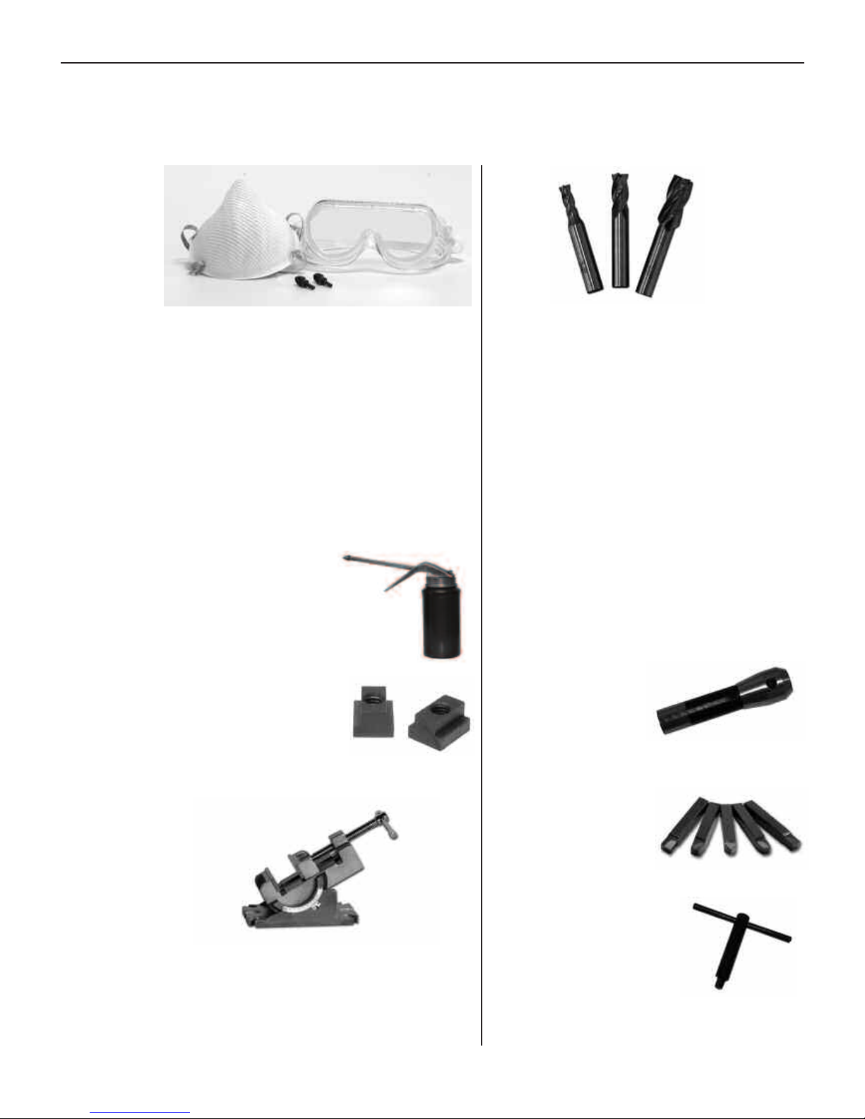
Items Packed in the Larger Smithy Box
The following items are packed in the larger of the two Smithy boxes.
3: Inventory Check List
! Air Mask
Part # 15-020
Quantity 1
! Protective Goggles
Part # 15-015
Quantity 1
! Ear Plugs
Part # 15-025
Quantity 1 Set
! Oil Can
Part # 80-100
Quanti
ty 1
! 7/16” T-Slot Nuts
P
art # 35-105
Quanti
ty 2
! Vise, 0-90º Adjustable Angle
Part # 32-110
Quantity 1
! End Mill, 4 FL HSS
1/4” w/3/8”
Shank
Part # 50-402
Quantity 1
! End Mill, 4 FL HSS
3/8” w/3/8” Shank
Part # 50-406
Quantity 1
! End Mill, 4 FL HSS
1/2” w/3/8” Shank
Part # 50-410
Quantity 1
! End Mill
Adapter R-8
P
art # 65-028
Quantity 1
! Lathe Bit Set
P
art # 43-000
Quantity 1 Set
(AR-8,AL-8,BR-8,
BL
-8 & E8)
! Lathe Chuck Key
Part # C30532
Quantity 1
Page 15
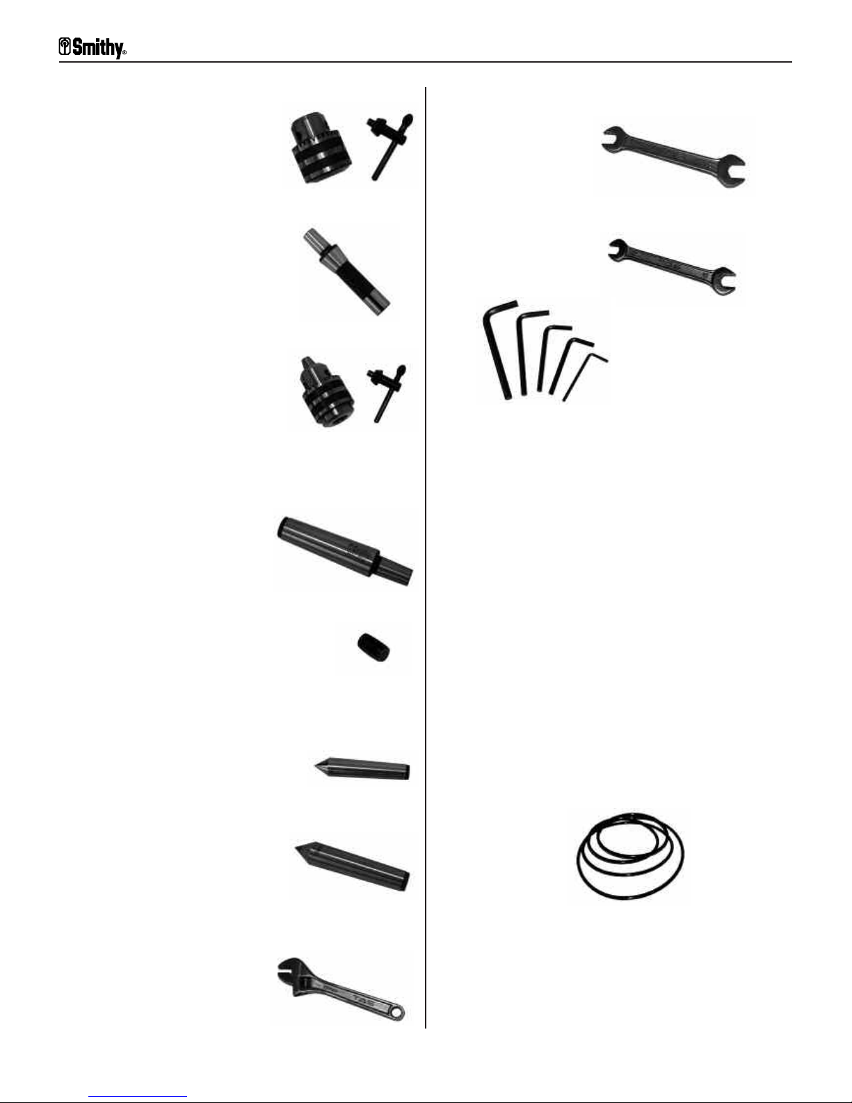
! Drill Chuck,
J
T3, 0.8-16 mm
with key
(for millhead)
Part # 72-003
Quantity 1
! Drill Chuck Arbor,
R-8/JT3
Part # 73-080
Quantity 1
! Drill Chuck,
JT33, 0.8-13 mm
with key
(for tailstock)
Part #72-001
Quanti
ty 1
! Drill Chuck Arbor,
MT3/JT33
Part # C30523
Quantity 1
! Arbor Plug
(M12 x 1.5 x 20 mm
setscrew)
Part # S12898
Quantity 1
! MT3 Dead Center
Part #41-003
Quantity 1
! MT4 Dead Center
Part # 41-004
Quantity 1
! 6” Adjustable Wrench
Part # G20006
Quantity 1
! 13/16 mm Open End
W
rench
Part # G20131
Quantity 1
! 10/12 mm Open End
Wrench
Part # G20101
Quantity 1
! Allen Wrench, 3 mm
Part # G20003
Quantity 1
! Allen Wrench, 4 mm
Part # C30540
Quantity 1
! Allen Wrench, 5 mm
Part # C30542
Quantity 1
! Allen Wrench, 8 mm
P
art # C30536
Quantity 1
! Allen Wrench, 10 mm
Part # G20002
Quantity 1
! Belt Set Millhead Belt
(Shipped On Machine)
Part # G05042 -A900 Or
P
art # G05042A 1/2”
Quantity 1
3-3
For
Assistance: Call
Toll Free 1-800-476-4849
Granite 1300 Series Operator’s Manual
Page 16
3: Inventory Check List
3-4
Or V
isit www
.smithy.com
! S
pindle to Speed Reduction
Pulley Belt
Part # G02043-A630 Or
Part # G02043A 1/2” x 27
Quantity 1
! Speed Reduction Pulley To Motor
Pulley Belt
Part # G02034-A710 Or
Part# G02034A-1/2” X 30
Quantity 1
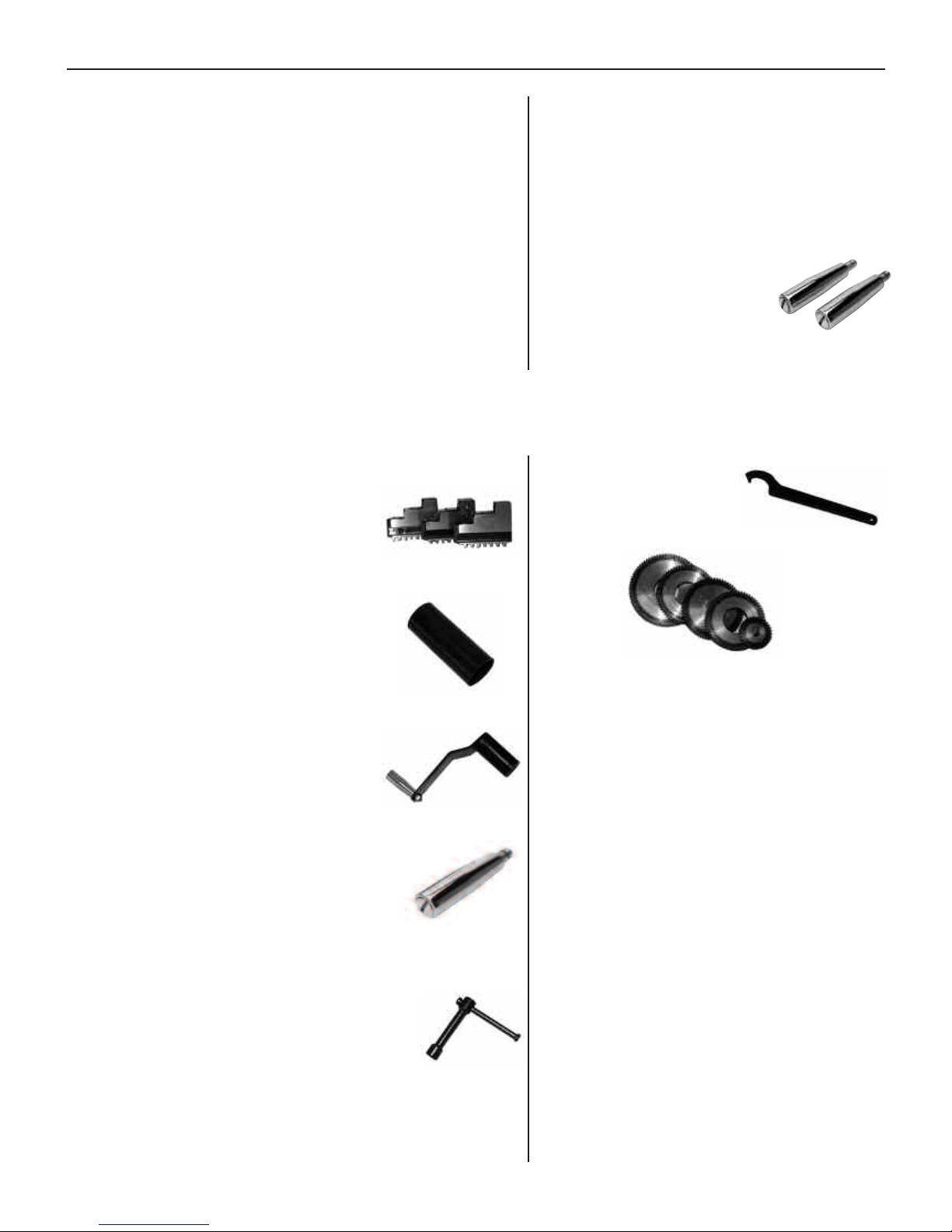
! Outside Jaws for
Lathe Chuck
Part #
Quantity 1
! Spindle Cover
Part # G05057
Quantity 1
! Millhead Crank
Part # G05123
Quantity 1
! Handle for
Leadscrew
Handwheel
P
art # G01028
Quanti
t
y 1
! Wrench, Compound
Angle Toolpost
Part # G06039
Quantity 1
! Spanner Wrench
Part # G20001
Quantity 1
! Metric Gear Set
Gear,33 Teeth
Part # G10116
Quantity 1
! Gear,63 Teeth
P
art # G10117
Quantity 1
! Gear,64 Teeth
Part # G10118
Quantity 1
! Gear,66 Teeth
Part # G10119
Quantity 1
! Gear,80 Teeth
P
art # G10120
Quantity 1
! Spindle to Motor Pulley Belt
(
Shipped On Machine)
Part # G03020 Or
Part # G03020A-1/2” x 41”
Quantity 1
! Crossfeed Handle &
Rack & Pinion
Travel Handle
Part # G08031
Quantity 2
Items Packed in Smaller Smithy Box
Page 17

! DVD, Machine
Tool Basics
Part # 12-003
Quantity 1
! Manual Cover
Part # 83-942
Quantity 1
! Quick Change
Toolpost*
(Mounted)
Part # 45-271
Quanti
ty 1
! Chuck Guard
(Mounted)
Part # 15-610
Quantity 1
! Operator’s Manual
Part # 83-950
Quantity 1
! Live Center**
(Large Box)
Part # 41-103
Quantity 1
! 3” Superlock Vise***
(Large Box)
Part # K99-310
Quantity 1
Items Packed in Plastic Bag
Additional Items for GN-IMX Series
* Quick Change Toolpost replaces standard turret for IMX series.
** Live Center additional item for IMX series.
***
Superlock Vise r
eplaces angle vise f
or IMS series.
Missing Items?
If y
ou find that an i
tem is missing or def
ectiv
e from your Quick Start Tool Pack
Call Us TOLL FREE 1-800-476-4849
or send an e-mail to info@smithy.com
within 30 days of receiving your machine so that we may assist you immediately.
Our sales and service technicians are available 8am to 5pm ET, Mondays to Fridays.
3-5
For
Assistance: Call
Toll Free 1-800-476-4849
Granite 1300 Series Operator’s Manual
Page 18
4-1
Or V
isit www
.smithy.com
Overview
This chapter will help you to familiarize yourself with the Smithy Granite 1300 models and
standard accessories. Figures 4.1 through 4.15 identify the major components and
functions of your machine. The photographs in this section depict a Granite 1324 model.
Distinguishing features are noted.
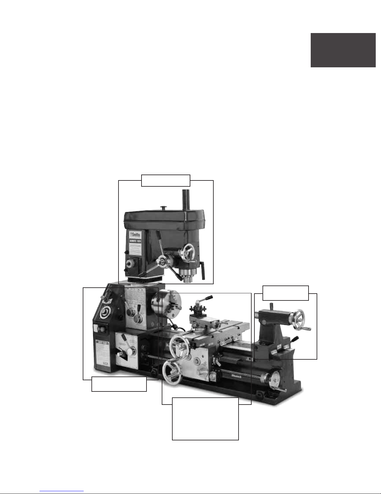
Major Features Identified
4
Machine Overview
Millhead
Powerhead
Carriage
Assembly &
Compound
Angle Toolpost
Figure 4.1 Granite 1324 Front View
Tailstock
Page 19
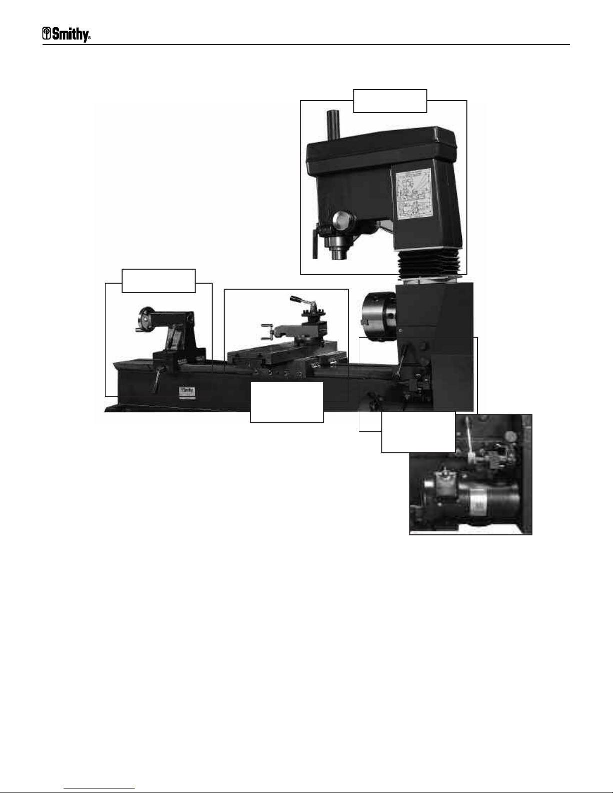
Figure 4.2 Granite 1324 Back View
Tailstock
Millhead
Carriage
Assembly
Motor
Assembly
Granite 1300 Series Operator’s Manual
4-2
For
Assistance: Call
Toll Free 1-800-476-4849
Page 20
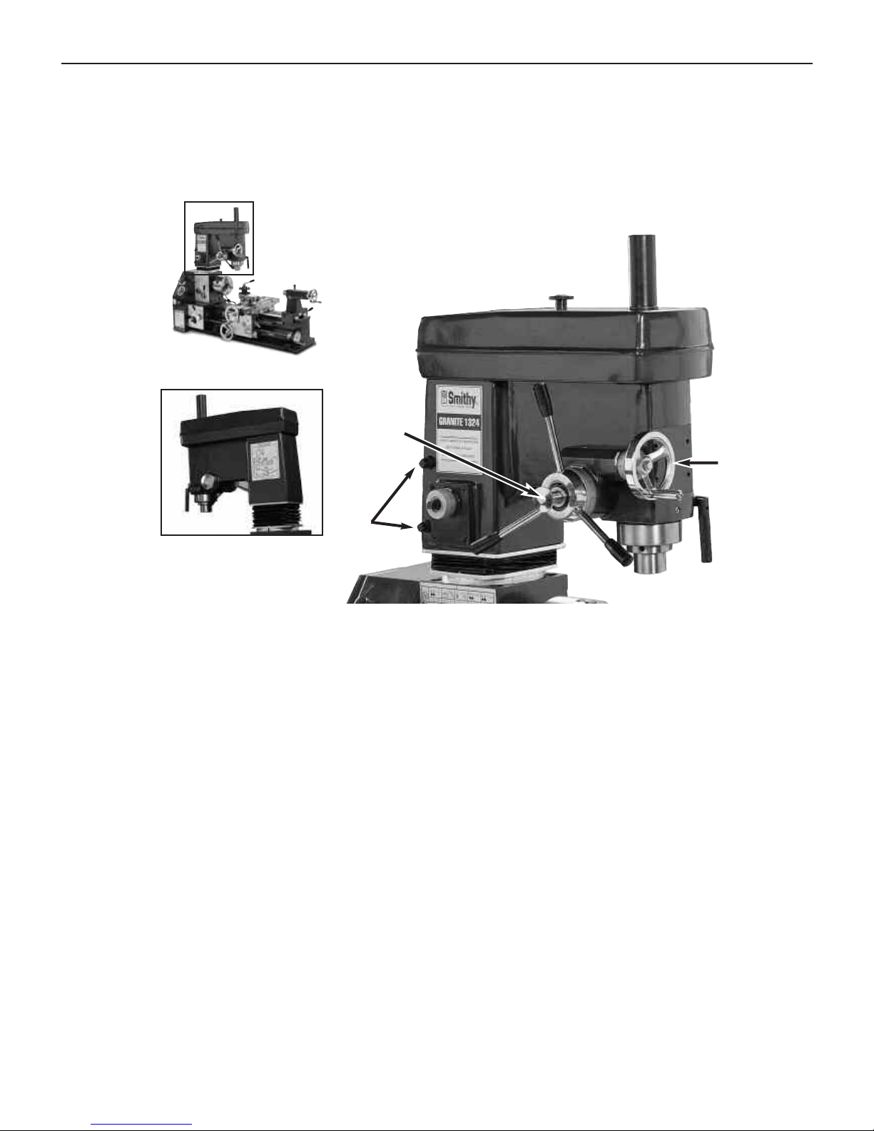
Millhead Components & Functions
The photos below show the front and back of the millhead of the Smithy Granite machine.
The millhead holds the tooling necessary to perform milling and drilling operations. The
following section identifies the components and functions of the millhead.
A. Spindle Cover - The spindle cover protects the spindle from dust and debris. It also
protects the operator from injury. The spindle cover should be in place whenever the
machine is in operation. The drawbar is located under the spindle cover.
B. Millhead Cover - The Mi
l
lhead co
v
er pr
otects the belt and pulleys of the millhead.
The co
v
er should always be in place when the machine is in operation.
C. Quill Lock - The quill lock locks the mill/drill quill in place during a horizontal milling
operation or while changing tools.
D. Mill/Drill Spindle - The mi
l
l dri
l
l spindle is an R-8 taper. It holds and rotates the the
tool
ing used during milling and drilling operation. The spindle also moves in and out of
the millhead quill. The quill is an internal part which is not seen in this picture.
E. Drill Press Handles - The drill press handles move the quill in and out of the mill
head during a dri
l
l
ing operation. Rotating the handles in a clockwise direction moves the
qui
l
l downward, out of the millhead casting.
F. Coarse Feed/Fine Feed Clutch - Pulling out the coarse feed/fine feed clutch knob
engages the drill press handles/coarse feed. Pressing the knob in engages drill/mill fine
feed hand wheel. To easily engage/disengage the clutch, rotate the drill press handles
slight
ly while pulling/pushing the knob.
A
B
C
D
E
F
G
H
I
J
Figure 4.3 Granite Millhead (Front & Back)
4: Machine Overview
4-3
Or V
isit www
.smithy.com
Page 21

G. Drill/Mill Fine Feed Handwheel - The handwheel controls the fine feed movement
of the quill in and out of the millhead.
H. Height Adjustment Drive - The height adjustment drive works with the millhead
crank to raise and lower the millhead. Insert the millhead crank over the stud, as in
Figure 4.4, rotate clockwise to raise the millhead and counter clockwise to lower the
millhead.
One revolution of the crank handle will move the millhead 0.25 inches.
I. Millhead Locking Studs - The locking studs secure the mi
llhead in posi
tion. Insert
the mi
llhead crank over the upper stud, rotate counterclockwise to unlock the stud.
Repeat the process on the lower stud. Position the millhead in the desired position and
lock BOTH locking studs before starting your machine.
J. Bellows - Bellows keep debris off of the Z-Axis column and rack.
Figure 4.4 Adjusting Millhead Height
Granite 1300 Series Operator’s Manual
4-4
For
Assistance: Call
Toll Free 1-800-476-4849
Page 22
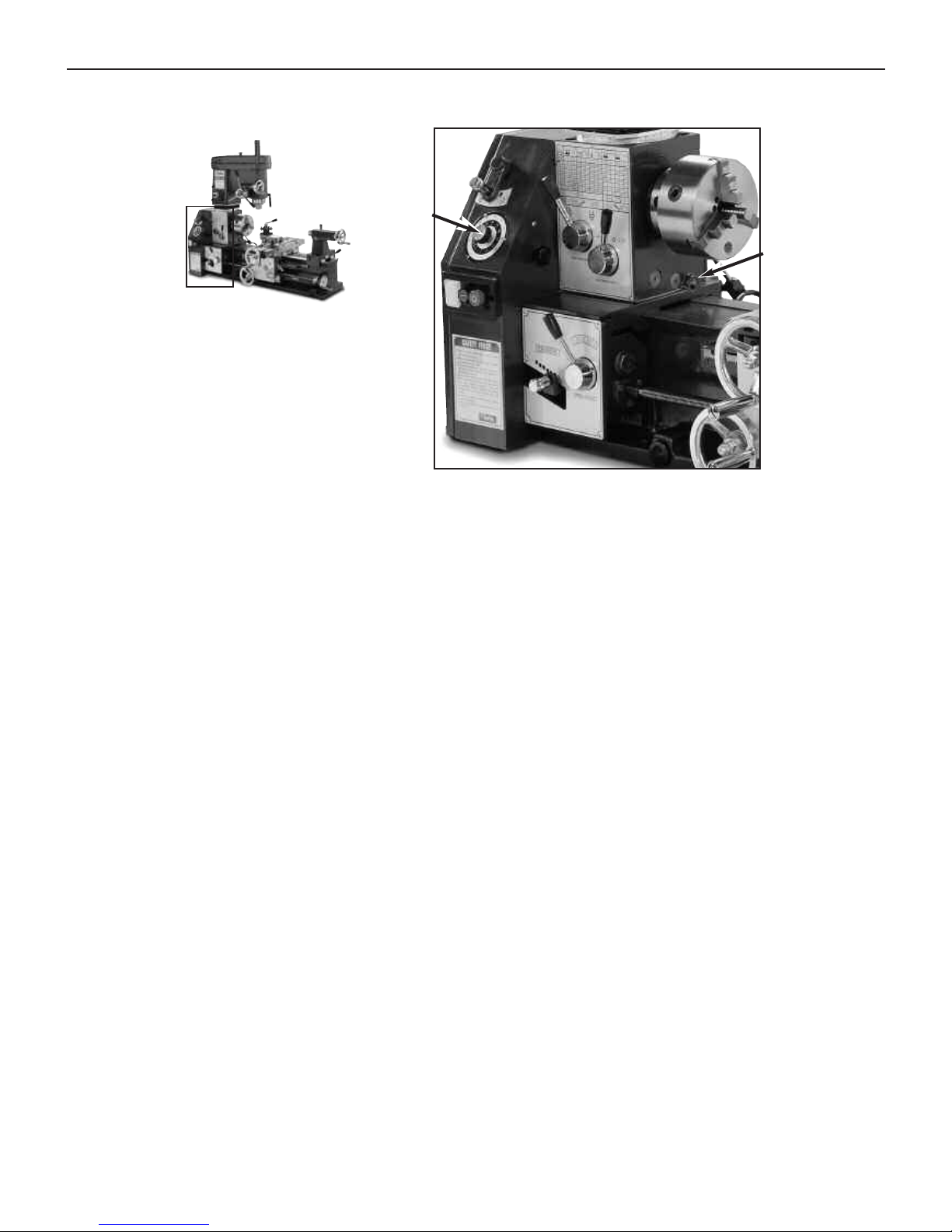
Powerhead Components & Functions
A. Lathe/Mill Clutch - This clutch engages the mi
ll portion of the Smith
y Granite LatheMill-Drill when pulled out and moved to the left. When moved to the right the lathe is
engaged. Center position is neutral.
B. Speed Dial - The speed dial contr
ols the motor rpm. Rotating clockwise increases the
speed.
C. Forward/Reverse & On/Off Switch - The red toggle button underneath the yellow
cover reverses the direction of the motor. The green middle button is the “power-on”
but
ton. The large red button is the stop button and cuts power to the machine.
D. Powerfeed Function Lever - Moving the lever to the left, powers the lathe
powerfeed. Moving the lever to the right powers the mill powerfeed.
E. Leadscrew Rotation Direction Handle - Positioning this handle to the right
causes the leadscrew to rotate clockwise. Positioning to the left causes the leadscrew to
r
otate counter
clockwise.
F. Selector Lever 1-7 - Used in conjunction with Selector Lever I-III to set feed rate or
pitch setting for cutting threads.
G. Selector Lever I-III - Used in conjunction wi
th S
elector Lev
er I
-7 to set f
eed r
ate
or pi
tch set
ting f
or cut
ting threads.
H. Jog Knob - Assists in meshing gears inside the quick change gear box which is
controlled by selector levers 1-7 and I-III. Rotating the knob helps align gears
I. Oil Level/Sight Glass - Normal oi
l lev
el is at the hal
f w
ay point, add oil if the level
of oi
l in the sight glass dr
ops below this level.
J. Quick Change Gear Box - Houses the gears that determine f
eed r
ates and gear
settings for cutting threads.
Figure 4.5 Granite Powerhead Parts (Front View)
A
B
C
D
E
F
G
H
I
J
4: Machine Overview
4-5
Or V
isit www
.smithy.com
Page 23

A. Oil Fill Port - Located direct
ly abo
ve the motor, it holds 8-10 oz of 30 weight oil.
Remove the screw to add oil as necessary.
B. Belt Tension - Mo
ves the motor pulley up and down releasing tension on the belts.
Pull the lever down to loosen the tension on the belt and push the lever up to add
tension to the belts.
C. DC Motor - Runs on standard 110 volt power.
A
B
C
Figure 4.6 Granite Powerhead Parts (Back View)
Granite 1300 Series Operator’s Manual
4-6
For
Assistance: Call
Toll Free 1-800-476-4849
Page 24
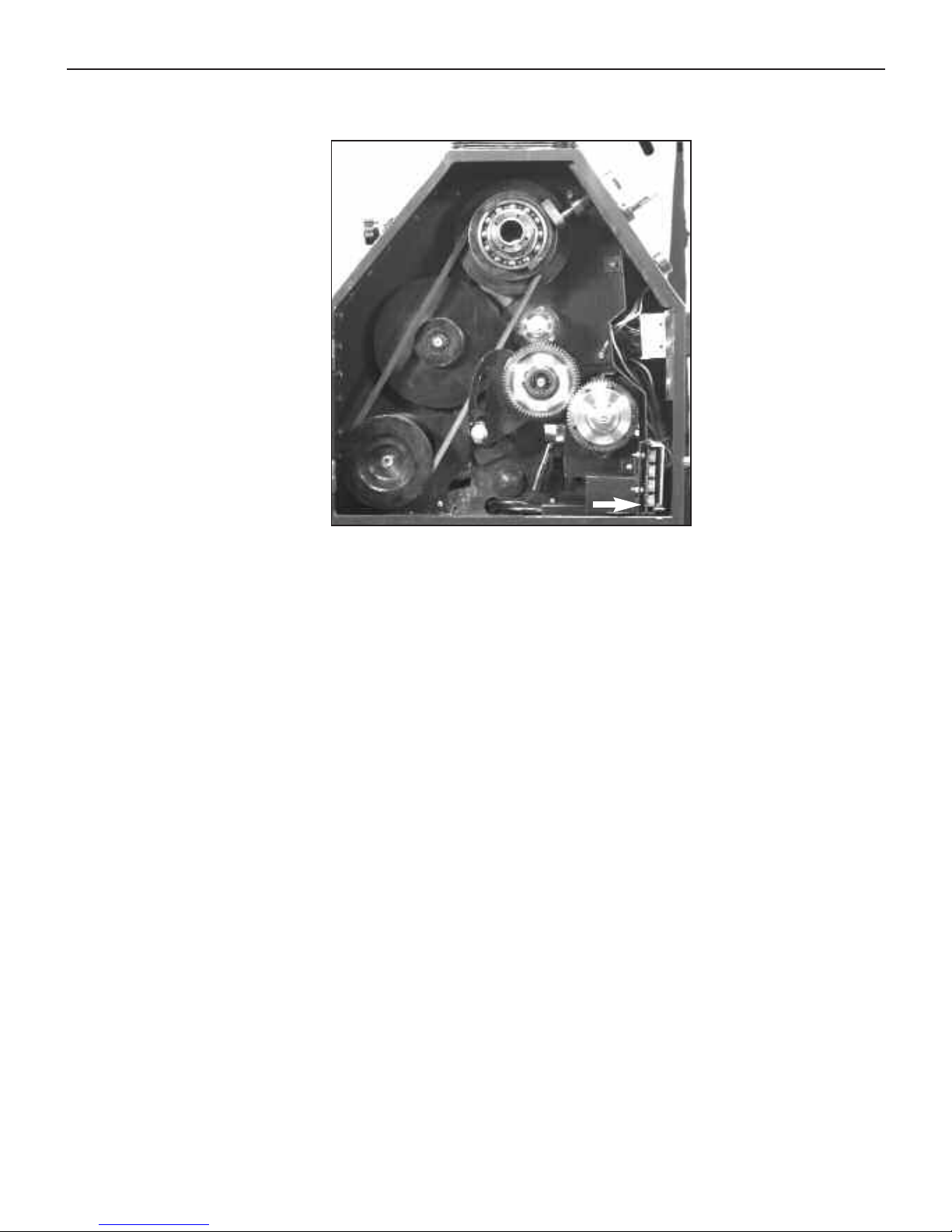
Pulley Box
The pulley box houses the drive pulleys, gears and power components.
L-1. Motor Pulley - A three-step pulley attached to the shaft of the motor.
L-2. Speed Reduction Pulley - Sits between the motor and spindle pulley and is used
for low speed operations when increased torque is desired.
L-3. Spindle Pulley - A two-step pulley attached to the main lathe spindle.
L-4. Change Gear A - A 30-tooth gear instal
led at the f
actory
. The change gears only
need to be reconfigured when cutting metric threads.
L-5. Change Gear B - A 60 tooth gear installed at the factory. The change gears only
need to be reconfigured when cutting metric threads.
L-6. Change Gear C - A 66
tooth gear that rides behind change gear B (60 tooth gear)
and is instal
led at the factory. The change gears only need to be reconfigured when
cutting metric threads.
L-7. Change Gear D - A 60 tooth gear instal
led at the f
actory
.
L-8. SCR Module - Converts the AC power coming into the machine to DC power for the
motor.
L-9. Inch/Metric Selector - Used when cutting threads. Pull the lever out toward the
oper
ator when cut
ting metric threads. When cutting inch (SAE) threads, make sure the
lev
er is pushed in toward the machine.
Figure 4.7 Granite Pulley Box (Inside)
L-1
L-2
L-3
L-8
L-4
L-5
L-6
L-7
L-9
L-10
4: Machine Overview
4-7
Or V
isit www
.smithy.com
Page 25
L-10. Leadscrew Clutch- Is designed to slip to reduce damage to the machine
apron if the carriage is accidentally run into the head of the machine.
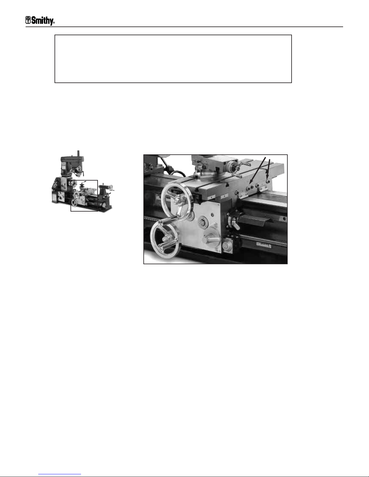
Carriage Assembly
The carriage assembly consists of:
• Crossslide table
• Carriage; the lower portion of the table that rides on the bed ways,
• Apron; the portion that hangs from the cross-slide table in front of the
machine.
The carriage moves by hand or by power along the bed ways. Its function is to support
the cutting tool rigidly while in the lathe mode and to secure the workpiece while in the
mill mode. The carriage can be locked into place with the lock found on the back of the
carriage.
The figure to the above right identifies and defines the major components of the carriage
assembly.
A. Cross-SlideTable - The top portion of the carriage assembly. It supports the
compound angle toolpost (not pictured) which holds the lathe cutters and tooling. The
table also supports y
our workpiece when oper
ating the mill. The cross-slide table has four,
7/16” sized t-slots for securing tooling and mounting workpieces.
! NOTICE !
There is a neutral position with this selector. Be sure that it is completey
engaged in either the metric or inch mode before you begin your threading
operation.
Figure 4.8 Granite Carriage Assembly
A
B
C
D
E
F
G
H
I
Granite 1300 Series Operator’s Manual
4-8
For
Assistance: Call
Toll Free 1-800-476-4849
Page 26

B. Cross-Slide Handwheel - This handwheel moves the table toward and away from
the operator along the Y-Axis. Rotating the handwheel clockwise moves the table away
from the operator while moving it counterclockwise moves the table toward the operator.
C. Longitudinal Handwheel - This handwheel is located at the bottom left of the
carriage assembly. Manually rotating the handwheel clockwise will move the carriage
assembly along the X-Axis towards the tailstock end of the machine. Rotating the
handwheel counter clockwise will move the the carriage assembly towards the headstock
end of the machine.One revolution moves the assembly approximately .040”.
NOTE:
This handwheel is for coarse movements only. Use the handwheel at the end of
the leadscrew for fine movement (0.001”)
D. Half-Nut Engagement Lever - This lever closes the half-nut on to the leadscrew.
When the half-nut is engaged, in the down position, the table assembly will be powered
to move right and left along the X-Axis leadscrew.
E. Longitudinal and Lateral Powerfeed Selector - This selector determines whether
the carriage will be power
ed to move along the X-Axis (longitudinal axis) or the Y-Axis
(lateral axis). When the lever is in the upper position the table will move along the Y-Axis.
When moved into the lower position, the table will move along the X-Axis. Center
posi
tion is neutral.
F. Threading Dial - The threading dial is used to coor
dinate consecutive cuts when
cut
ting threads. Restarting each cut from the same point on the dial ensures that each
cut follows the same path, leading to accurately machined threads.
G. Saddle - The saddle supports the cr
oss-sl
ide table and mo
v
es along the X
-
Axis of the
machine.
H. Apron - The apron houses the gear mechanism for the X and Y-Axis powerfeed.
! NOTICE !
The hal
f-nut engagement lever is only engaged for rapid
travel or threading operations.
! NOTICE !
The threading dial can only be used when cutting inch
(S
AE) threads.
4: Machine Overview
4-9
Or V
isit www
.smithy.com
Page 27
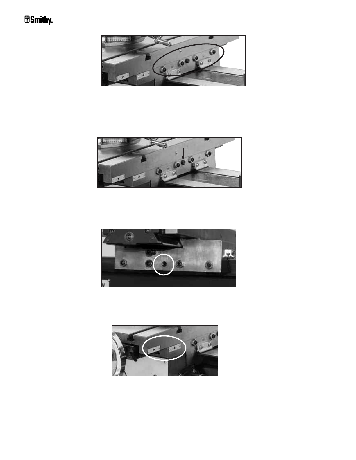
I. Carriage Gib Adjustment Screws - These screws press a small metal plate (the gib)
to the ways of the bed, increasing or decreasing the tension when moving the cross-slide
assembly. (Figure 4.9)
J. Carriage Lock (Y-Axis) - is an M8 screw. Turning the screw clockwise will prohibit
movement of the carriage along the Y-Axis. (Figure 4.10)
K. Carriage Lock X-Axis - is an M8 screw located on the back side of the carriage.
Turning this screw clockwise locks the carriage to the bedways.
L. Travel Indicators - mark the limit of travel on the crossfeed table. Running the top
portion of the indicator located on the tai
lstock side of the cr
oss-sl
ide table past the lower
indicator on the bot
tom portion of the table (carriage) wi
ll cause serious damage to your
machine.
Figure 4.9 Granite Carriage Gib Adjustment Screws (Quantity 4)
Figure 4.11 Granite Carriage Lock X-Axis (Rear View)
Figure 4.12 Granite Carriage Travel Indicators
Figure 4.10 Granite Carriage Lock Y-Axis
Granite 1300 Series Operator’s Manual
4-10
For
Assistance: Call
Toll Free 1-800-476-4849
Page 28
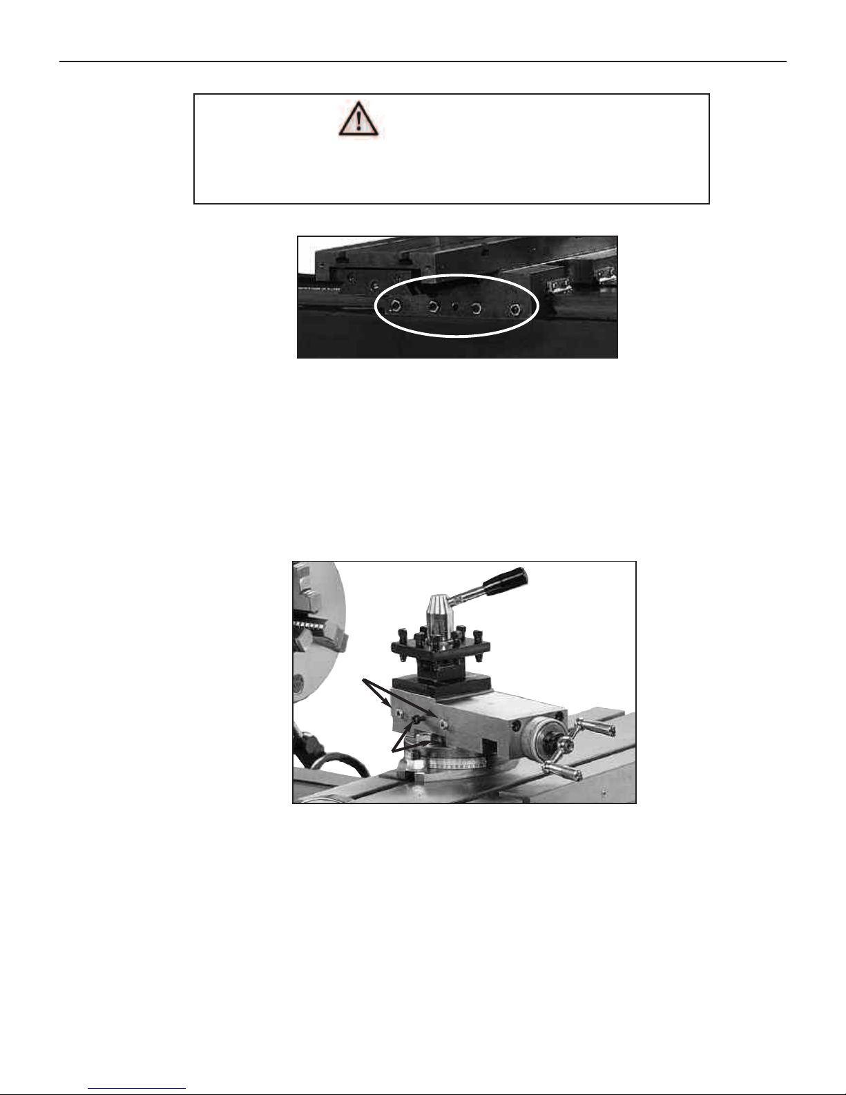
M. Carriage Gib Adjustments Screws - when screwed in, these screws press a small
metal plate (the gib) to the ways of the bed, incr
easing or decreasing the tension when
moving the carriage assembly along the bed ways.
Carriage Assembly-Compound Angle Toolpost
The compound angle toolpost is bol
ted to the cr
oss-sl
ide table wi
th 10mm T
-B
olts. The
compound angle toolpost swiv
els to an
y angle horiz
ontal to the lathe axis. The
calibrations on the swivel base are in degrees, (60º-0º-60º). The following section
identifies and explains the functions of the toolpost.
A. CATP (Compound Angle Toolpost) Lock down handle - The handle r
otates
counter
clockwise to loosen the tension on the f
our position turret, allowing the user to
turn the turr
et 90º per turn.
Figure 4.13 Granite Carriage Gib Adjustment Screws (Rear View)
Figure 4.14 Granite Compound Toolpost
Do not let the top indicator mark travel past the bottom indicator
mark on the right side (side facing tailstock) of the carriage assembly.
WARNING
A
B
C
D
E
F
G
H
I
4: Machine Overview
4-11
Or V
isit www
.smithy.com
Page 29
B. Turret Bolts - These bolts secure your tooling to the turret.
C. 4 Position Turret - The turret holds up to 1/2” tooling. The turret can support up to
4 tools.
D. Compound Slide - The compound slide moves the tooling in towards and away from
the workpiece.
E. Floating Dial - The floating dial can be repositioned to zero at any point to measure
tool feed in or out.
F. CATP Carriage -The carriage supports the compound slide and is bolted directly to
the swivel base.
G. Swivel Base - The swivel base secures the CATP and allows it to rotate 360º in either
direction. A calibrated scale at the bottom of the base shows positioning in degrees from
60º-0º-60º.
H. Slide lock - This slide lock locks the compound slide to the carriage to secure the slide
in position.
I. Compound Gib Adjustment Screws - These screws press a small metal plate (the
gib) to the w
ays of the bed, increasing or decr
easing the tension when mo
ving the
compound slide.
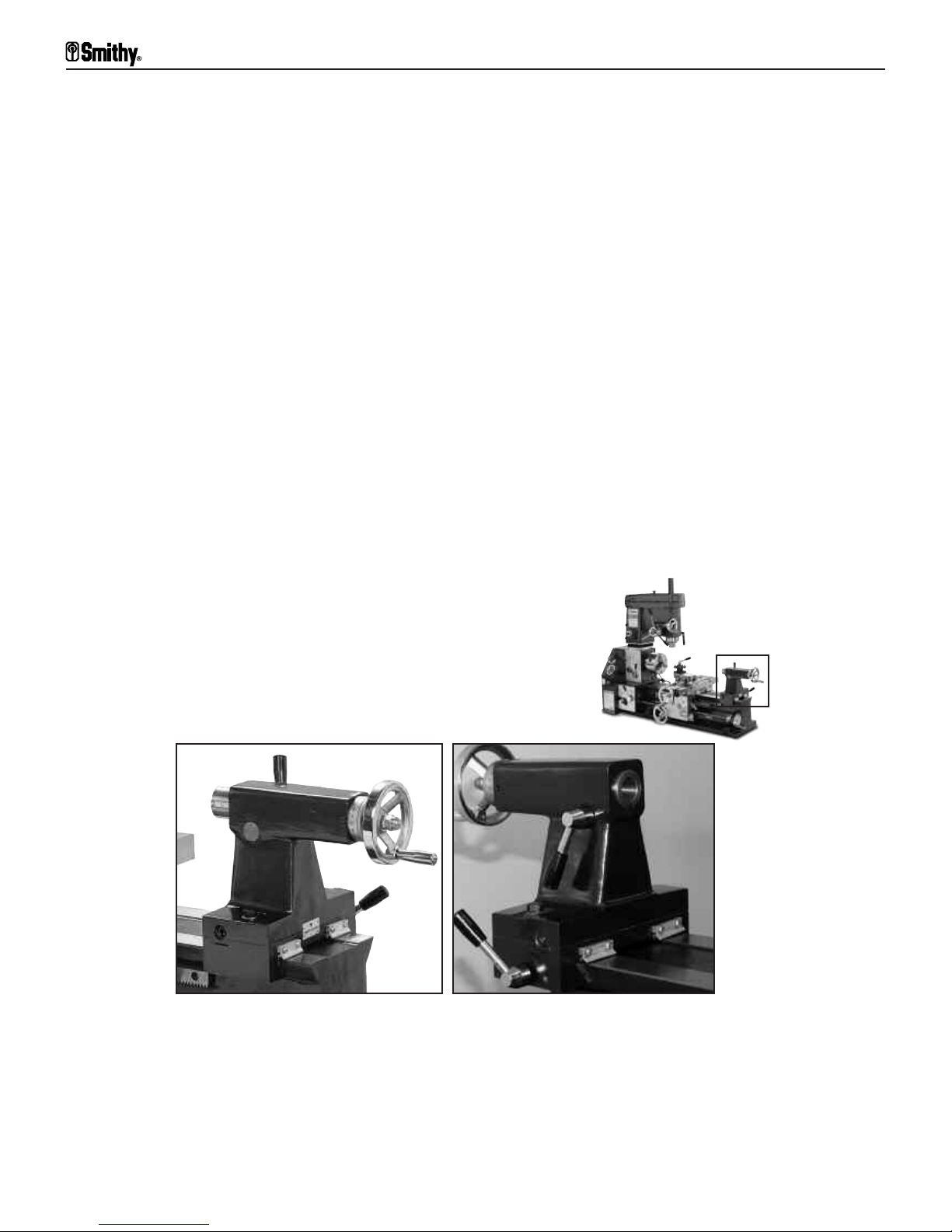
Tailstock
The tailstock holds tool
ing that supports the end of a workpiece. It also holds tool
ing such
as center dri
l
ls, reamers and taps. It moves along the bed of the machine and can be
stopped and locked in position at any point on the bedways. The photos above depict the
tailstock of the Granite machine. This section will identify and define major components
and functions of the Granite tailstock.
A
C
D
E
F
G
B
Figure 4.15 Granite Tailstock (Front & Back)
Granite 1300 Series Operator’s Manual
4-12
For
Assistance: Call
Toll Free 1-800-476-4849
Page 30

A. Tailstock Body - This is the main casting of the tailstock.
B. Off-Setting Lock Bolts -These bolts lock the top base of gthe tailstock and prevent
it from moving off center.
C. Tailstock Handwheel -This handwheel moves the tailstock barrel in and out of the
tailstock body.
D. Tailstock Lock -This locks the tailstock body to the bed ways.
E. Tailstock Barrel Lock -This locks the barrel into position.
F. Tailstock Barrel -The barrel holds the MT3 tooling that supports the end of the
workpiece.
G. Tailstock Off-Setting Bolts -These bolts allow the user to offset the toolpost for
cutting tapers.
For Granite MAX and I-MAX Series Machines
The following are some of the modifications and improvements for the Granite MAX and
Granite Industrial MAX machine series.
A. 30% Longer Millhead - An extended millhead to
accept larger workpieces for more efficient milling
operations.
B. Crash Protection System (Y-Axis) - A unique shear pin design that protects your
machine from major damage if the machine is run past its limits of travel. Found inside
the carriage assembly
.
C. Electrical Overload Protection - Improvement on the powerhead section of the
machine that safely shut offs the machine for prolonged motor life.
D. Extended Tailstock Travel - Dri
l
l or r
eam deeper wi
th 3” travel, also reach farther
across the table with the center securely placed in the tailstock.
E. Quick Change Toolpost (For Idustrial MAX Series
Only)
- The fastest, most convenient way to change a tool.
4: Machine Overview
4-13
Or V
isit www
.smithy.com
Page 31

Overview
The Quick-Start Manual you received before delivery of your Smithy machine
provides detailed instructions for mounting and locating your machine. Please
complete those instructions if you have not already done so. As you unpack, it
is a good idea to inventory the parts. (See chapter 3 for a complete list.) Before
operating your machine, you should assemble the remaining components of
your machine, clean the machine, and lubricate it. This section will guide you
through those steps.
Assembly of Minor Components
The installation of the drill chuck, arbor and arbor plug; mill spindle covers; and several
handles should be completed according to the procedures described below.
Drill Chuck and Arbor
Before proceeding both the arbor and the chuck should be thoroughly cleaned to ensure
a good fit. Once cleaned attach the chucks to the respective arbors. Follow the steps
below to achieve the best possible fit.
Step 1: Place the arbor in a f
reezer for about 1 hour to slightly shrink the metal.
Step 2: Remove the cold arbor from the freezer and place it into the drill chuck.
Step 3: Use a soft mallet or a block of wood to tap the end of the arbor.
Step 4: Allow the arbor to return to room temperature.
5
Preparing Your Machine
For Operation
Figure 5.1 Installing Arbor into Chuck
5-1
For
Assistance: Call
Toll Free 1-800-476-4849
Chuck
Jacobs Taper
MT3 Arbor
Page 32

Mill Spindle Cover
The mill spindle cover slides over the flange on the top of the millhead.
! NOTICE !
Arbor Plug
Install the plug setscrew (S12898 into the tailstock arbor before inserting the
arbor into the tailstock. A plug is installed in the tailstock arbor (the MT3 to JT33
arbor
, part number C30523), which allows the ejector pin inside the tailstock to
eject the arbor when the tailstock barrel is retracted.
Morse Taper 3 (MT3) tooling is used in the tailstock of the machine. R-8
tooling is used in the millhead of the machine and used in conjunction with a
dr
awbar.
Figure 5.2 Installing Arbor Plug
Figure 5.3 Installing Mill Spindle Cover
Do not operate your machine without the mill spindle
cover. Doing so could cause harm to yourself or your
machine.
WARNING
5
: Preparing Your Machine For Operation
5-2
Or V
isit www
.smithy.com
MT3 Arbor
Plugs
Page 33

Handles
Install any handles or handwheels that have been removed for shipping. Handles can be
hand installed and tightened with a flat-head screwdriver. Remove and reverse the
tailstock handwheel.
Cleaning & Lubricating Your Machine
Smithy machines are shipped with a light protective grease coating that must be removed
prior to use. Use a noncorrosive kerosene or white mineral spirits to remove the coating.
WD-40® also works well.
Once cleaned, your Smithy must be lubricated. Make sure to lubricate carefully and
thoroughly before starting the machine. Use a pump oil can and a supply of good
qual
ity SAE30 weight nondetergent oil or 30-weight compressor oil. Lubricants can be
obtained at most home and building supply stores. A lubrication point chart can be found
on the backside of the millhead.
Lubrication Schedule
Lubrication depends a lot on the use of your machine and your climate. The schedule
below is intended to be used as a guide, use your best judgement for lubricating your
machine based on your use and environment.
Check Oil Before each use
Oil Ports Before each use
Add Oil As Needed
See Chapter 11 for a complete maintenance schedule.
Lubrication Points
Follow the instructions on the next page and refer to the lubrication chart on the
backside of the mi
l
lhead.
Figure 5.4 Installing Handles
Granite 1300 Series Operator’s Manual
5-3
For
Assistance: Call
Toll Free 1-800-476-4849
Page 34

Gearbox
Open the gearbox door. Lightly grease the gears with a good quality molybdenum or
lithium grease or motorcycle-chain lubricant.
Check the oil sight glass under the chuck. If necessary, add oil until the sight glass is half
full. The oi
l-fill plug is at the back of the headstock above the motor. Be careful not to
overfill, the gearbox requires only 8 to 10 ounces of oil.
Figure 5.5 Brush a thin layer of lithium grease over
the gear quadrant in the pulley box
Figure 5.6 The oil level should be half way in the oil site glass
located under the lathe spindle.
Figure 5.7 Add oil through the oil port located
on the back side of the headstock.
Oil should be at
the mid point in the
site glass.
5: Preparing Your Machine For Operation
5-4
Or V
isit www
.smithy.com
Page 35

Ways
Run the carriage as far to the left as possible. Put a few drops of oil on the ways. Run
the carriage to the extreme right and repeat.
Carriage Assembly-Saddle
Lubricate the four oil buttons of the cross-slide table
There are two buttons on both the right (tailstock) side and left side (head stock) of the
carriage for the ways.
Figure 5.8 Carriage Assembly Saddle Oil Points
Granite 1300 Series Operator’s Manual
5-5
For
Assistance: Call
Toll Free 1-800-476-4849
Page 36

Carriage Assembly-Cross-Slide Table
There is one button on each side of the cross slide for the cross-slide ways.
Compound Angle Toolpost
Oil the two buttons on the top of the compound rest.
Figure 5.9 Carriage Assembly Cross Slide Table Points
Figure 5.10 Oil the Compound Angle Toolpost at its oil points
5: Preparing Your Machine For Operation
5-6
Or V
isit www
.smithy.com
Page 37
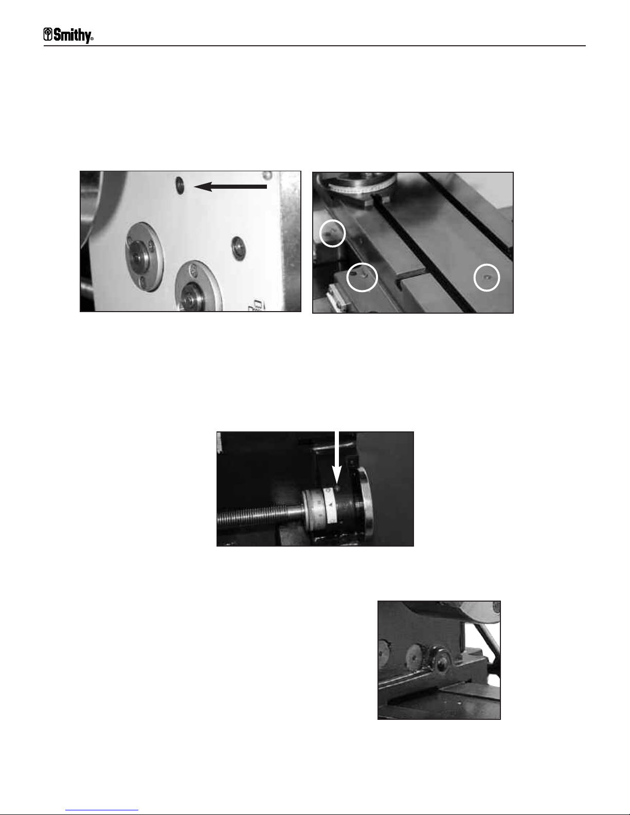
Cross-Slide Screw
Oil the cross-slide screw. The first oil button is located on the apron next to the crossslide dial and the other is found on the top of the cross-slide table.
Oil the buttons between the cross-slide and longitudinal-feed handwheels (at right).
Leadscrew
Oil the support for the right end of the leadscrew. Put a few drops of oil along the
leadscrew itself.
Oil Drip
Oil the end of the oil-drip trough from inside the gear box.
Figure 5.11 A & B Cross-Slide Screw Apron Oil Points
and Cross-Slide Screw Table Oil Points
Figure 5.12 Leadscrew Oil Point
Figure 5.13 Oil Drip
Granite 1300 Series Operator’s Manual
5-7
For
Assistance: Call
Toll Free 1-800-476-4849
Page 38

Quick Change Gear Box
Use a spray can of lithium grease or motorcycle-chain lubricant. Spray inside the
quick-change gearbox through the slot for the powerfeed (1-7) selector.
Tailstock Barrel
Oil the two buttons on top of the tailstock.
Mill/Drill Clutch, Fine Feed
Oil the button on top of the mill/drill clutch housing.
Figure 5.14 Oil the Quick Change Gear Box through the Powerfeed Slot
Figure 5.15 Tailstock Barrel Oil Points
Figure 5.16 Mill/Drill Clutch Oil Points
5: Preparing Your Machine For Operation
5-8
Or V
isit www
.smithy.com
Page 39

Adjusting Gibs
The Granite 1300 models have a series of straight gibs. The gibs are found on the
carriage, the cross-slide table, compound angle toolpost and the tailstock. These gibs
should be adjusted periodically to maintain accuracy and smooth operation.
Carriage Assembly-Saddle
Adjust the gibs on the saddle assembly using the procedure below.
Step1: Loosen the four jam nuts on the back side of the saddle with the 6” adjustable
wrench that was shipped with your machine.
Step 2: Back out the gib adjusting screws found on the back side of the saddle two turns
wi
th the 4 mm al
len wr
ench.
Step 3: Using the 4 mm Allen wrench, tighten each of the four gib adjustment screws
until they are lightly touching the gib.
Step 4: B
ack the gib adjustment scr
ews out 1/8 to 1/4 turn.
Step 5: With the adjustment screws now set at roughly the same position, make the
fine adjustments on each individual screw. Starting with one of the inner screws, slowly
tighten the screw while moving the carriage assembly by turning the leadscrew
handwheel unti
l y
ou f
eel sl
ight r
esistance.
! NOTICE !
Always make sure your machine is well lubricated before
adjusting the gibs.
Do not apply excessive force.
Figure 5.17 Carriage Gibs
CAUTION
Granite 1300 Series Operator’s Manual
5-9
For
Assistance: Call
Toll Free 1-800-476-4849
Page 40

Step 6: Once slight resistance is felt, hold the gib adjustment screw in position and
t
ighten the jam nut.
Step 7: Repeat steps 5 and 6 with the other inner screw and then with the two outer
screws.
Adjusting the Gibs on the Carriage Assembly Cross-Slide Table
Adjust the gibs on the cross-slide table using the procedure below.
Step 1: Loosen the four jam nuts on the tailstock side on the table with the 6” adjustable
wr
ench that was shipped with y
our machine.
Step 2: Back out the gib adjusting screws two turns.
Step 3: Using the 4 mm Al
len wrench, tighten each of the four gib adjustment screws
until they are lightly touching the gib.
Step 4: B
ack the gib adjustment scr
ews out 1/8 to 1/4 turn.
Step 5: With the adjustment screws now set at roughly the same position, make the
fine adjustments on each individual screw. Starting with one of the inner screws, slowly
tighten the screw while moving the cross-slide table by turning the cross-slide handwheel
unti
l y
ou f
eel slight resistance.
Step 6: Once slight resistance is felt, hold the gib adjustment screw in position and
tighten the jam nut.
Step 7: Repeat steps 5 and 6 with the other inner screw and then with the two outer
scr
ews.
Do not apply excessive force.
Figure 5.18 Gib Adjustment Screws - Cross-Slide Table
CAUTION
5: Preparing Your Machine For Operation
5-10
Or V
isit www
.smithy.com
Page 41

Adjusting the Gibs on the Compound Angle
Toolpost
Adjust the gibs on the compound-angle toolpost using the procedure below.
Step 1: Loosen the jam nuts on the side of the compound-angle toolpost with the
6 inch adjustable wrench.
Step 2: Back out the gib adjustment screws out two turns .
Step 3: Using the a flat-head screw driver, tighten the two gib adjustment screws until
they are lightly touching the gib.
Step 4: Back the gib adjustment screws out 1/8 to 1/4 turn.
Step 5: With the adjustment screws now set at roughly the same position, make the
fine adjustments on each individual screw. Starting with the screw closest to the handle,
slowly tighten the screw while moving the compound angle toolpost by turning the
compound-slide handle until you feel
slight
resistance.
Step 6: Once slight resistance is felt, hold the gib adjustment screw in position and
tighten the jam nut.
Step 7: Repeat steps 5 and 6 with the remaining gib adjustment screw.
Figure 5.19 Gib Adjustment Screws - Compound Angle Toolpost
Do not apply ex
cessiv
e force.
CAUTION
Granite 1300 Series Operator’s Manual
5-11
For
Assistance: Call
Toll Free 1-800-476-4849
Page 42

Adjusting the Gibs on the Tailstock
Adjust the gibs on the tailstock using the procedure below.
Step 1: Unlock the tailstock.
Step 2: Remove the outer setscr
ews with the 4 mm Allen wrench provided.
Step 3: Using the 4 mm Al
len wrench, tighten each gib adjustment screw until it
touches the gib lightly.
Step 4: Back each gib adjustment screw out 1/4 turn.
Step 5: Reinstall each outer setscrew and bottom it against the inner screws to lock the
corresponding inner screw in place.
Step 6: Repeat steps 2 through 5 on the remaining screw.
Figure 5.20 Gib Adjusting Screws - Tailstock (Shown with tailstock lock removed)
! NOTICE !
Ther
e ar
e two setscrews in each hole. To tighten the
tailstock gibs the outer setscrews need to be removed.
! NOTICE !
Unlike the carriage, cross-slide and compound-angle toolpost gib
adjustments, you will not feel a slight resistance when moving the
tai
lstock. The tai
lstock wi
l
l be lock
ed to the w
a
ys with the tailstock
lock. The objectiv
e of adjusting the tai
lstock is to ensur
e that the
tailstock remains parallel to the ways.
5: Preparing Your Machine For Operation
5-12
Or V
isit www
.smithy.com
Page 43

Adjusting Backlash
Backlash is lost motion in the screw. The user will notice an initial small movement in the
handwheel before the screw responds. The procedures in this section will help minimize
backlash.
Adjusting Backlash from the Cross-Slide Screw
Before making any adjustments to the cross-feed screw system, all the gibs on the table
and carriage system should be checked and adjusted as described previously.
Excessive backlash in the cross-slide can come from three different places.
• The fit of the cross-slide screw to the front screw mount
• The fit of the cross-slide screw into the brass crossfeed nut
• The fit of the br
ass cross-feed nut into the carriage casting
There are adjustments for each of these areas. Follow the procedures below to make
each adjustment.
Adjusting Backlash Cross-Slide Screw to the Front
Screw Mount
Step 1: Loosen the two nuts that hold the cross-slide handwheel on to the end of the
cross-slide screw.
Step 2: Tighten the inner nut slowly whi
le checking the ease of movement of the
cross-slide handwheel. When the screw starts to become difficult to turn, loosen the nut
slightly so that the screw turns freely.
Step 3: Hold the inner nut in place with a wrench and tighten the outer nut against the
inner nut to lock both nuts in position.
Step 4: Recheck the backlash.
Figure 5.21 Loosen the two outer nuts holding the handwheel
Granite 1300 Series Operator’s Manual
5-13
For
Assistance: Call
Toll Free 1-800-476-4849
Page 44
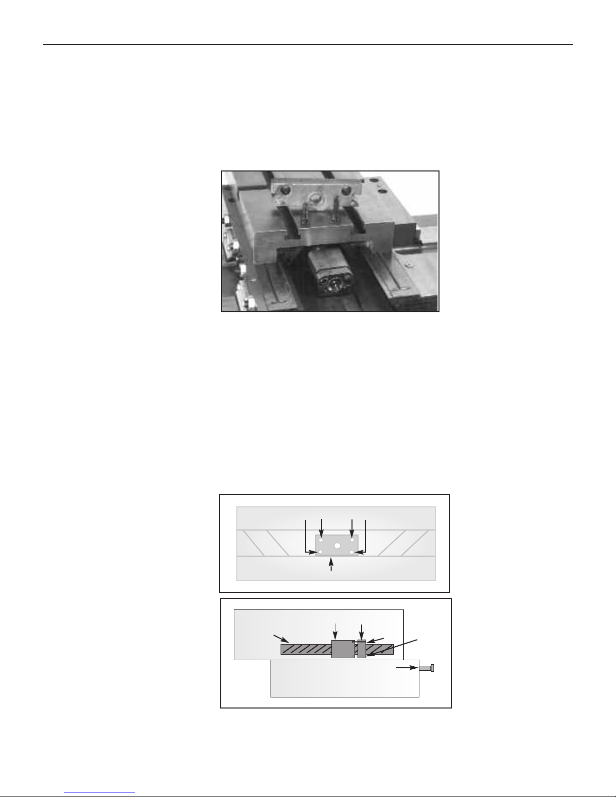
Cross-Slide Screw to Brass Nut & Nut to Saddle
If there is still excess backlash after the previous adjustment, the backlash is either
between the cross-slide screw and the brass nut or between the brass nut and the
saddle. The following procedure covers both adjustments.
Step 1: Remove the rear support on the backside of the cross-slide table.
Step 2: Loosen the allen bolt that locks the brass nut into the saddle. (See Figure 5.23)
Step 3: Use the handwheel to mo
ve the cross-slide table toward the operator side of
the machine. Watch under the table from the backside and stop before the cross-slide
scr
ew comes out of the brass nut.
Step 4: Slowly tighten the four adjusting screws on the brass nut, one at a time, until
a sl
ight drag is felt while turning the cross-slide handwheel. It is best to continue
turning the handwheel back and forth while adjusting the nut to balance ease of
operation and backlash.
Figure 5.22 Remove mount on backside of the table
to access the brass cross slide nut
Figure 5.23 Tighten the adjusting screws on the brass nut
Cross-slide table
Cross-slide screw
2 Piece Brass Nut
Adjusting Screws
Saddle
Locking Bolt
Saddle
Brass Nut
Adjusting Screws
Table view from
rear of machine.
5: Preparing Your Machine For Operation
5-14
Or V
isit www
.smithy.com
Page 45

Step 5: Reinstall the rear support and tighten the locking bolt for the brass nut.
Step 6: Recheck the backlash on the cross-slide.
Adjusting Backlash from the Longitudinal
Leadscrew
Excessive backlash in the longitudinal feed can come from two places.
• The fit of the longitudinal feed screw to the right-hand mounting trestle
• The fit of the half-nut to the feed screw
Engage the half-nut lever. Slowly turn the longitudinal handwheel clockwise as viewed
from the right end of the machine and watch the gap between the dial and the feed screw
mounting trestle. Reverse the direction you are turning the feed screw and see if the gap
increases slightly. If so then there is some backlash in the mounting. Follow the
procedure below to reduce the backlash.
Adjusting the fit of the longitudinal feed screw
to the right-hand mounting trestle
Step 1: Remove the retaining screw and washer in the right end of the longitudinal feed
handwheel.
! NOTICE !
If you find that the four adjusting screws will not stay in place, use
a small amount of thread-locking compound to keep the screws
tight. If you use a Lock-Tite® product, use the Lock-Tite® Purple,
not Red which will not allow for future adjustments
Figure 5.24 Adjusting backlash from the leadscrew
Granite 1300 Series Operator’s Manual
5-15
For
Assistance: Call
Toll Free 1-800-476-4849
Lead Screw &
Dial
Mounting
Trestle
Spanner
Nut
Handwheel
Retaining Screw
& Washer
Page 46

Step 2: Unscrew the handwheel from the end of the feed screw.
Step 3: Using a punch and a small hammer, tighten the spanner nut about one-eighth
of a turn and recheck the backlash in the leadscrew.
Step 4: If backlash is acceptable, replace the handwheel, washer, and retaining screw.
If more adjustment is needed, repeat step 3 above.
Half-Nut to Leadscrew Backlash
Worn threads on the half-nut can cause excessive backlash in the longitudinal direction.
Half nuts are made of a brass-like material and do wear out over a period of time. The
only fix for a worn half nut is to replace the worn nut with a new one.
Adjusting Mill Feed Backlash
Excessive backlash in the vertical fine feed can come from two places.
• The fit between the worm gear and the pinion gear shaft
• The fit of the quill gear to the quill rack
Adjusting the Fit Between the Worm Gear and
Pinion Gear Shaft
F
ollow the procedure below to adjust the fit between the worm gear and pinion gear.
Step 1: Remove the fine-feed handwheel and dial.
Step 2: Loosen the two setscrews that hold the left and right worm gear bearing sup-
ports in place. They are located on top of the vertical feed housing at the left and right
end of the worm gear.
! NOTICE !
The longitudinal handwheel (R
ack & Pinion) is intended for rapid,
coarse feed and is not calibrated for fine measurement. There is no
backlash procedure for this mechanism.
5: Preparing Your Machine For Operation
5-16
Or V
isit www
.smithy.com
! NOTICE !
The bearing housing has two holes in the outside surface
to allow a punch or spanner wrench to turn the housing.
Page 47

Step 3: Use a small spanner wrench or a punch with a small mallet to rotate the
bearing supports one at a time. The support bearings ar
e mounted slightly of
f center in
these housings and rotation of the housings will raise or lower the worm gear down
towards the pinion gear. The bearing support on the right should be rotated clockwise
and the left should be rotated counter clockwise. Rotating the right and left bearing
supports should be done in conjunction with each other.
Step 4: Turn the right housing and watch the worm gear shaft to see in which direction
it moves. Turn the housing in the direction that will move the worm gear down towards
the pinion gear.
Step 5: Move to the left housing and repeat step 4.
Step 6: Alternate moving the front a little and then the rear a little while turning the
worm gear to check for binding.
Step 7: Stop as soon as resistance is felt in the rotation of the worm gear. The
adjustment is completed.
Step 8: Tighten the setscrews to the bearing housings to lock adjustment in place.
Adjusting the fit of the Quill Gear to the Quill
Rack
Adjusting the fit between the quill shaft feed gear and the quill rack is done using the
split section of the feed gear. The feed gear is made up of two parts.
• A wide section that is locked to the feed shaft by a key and has a fixed
position on the shaft
Granite 1300 Series Operator’s Manual
5-17
For
Assistance: Call
Toll Free 1-800-476-4849
Figure 5.25 Adjusting backlash from the mill feed
Setscrews
Bearing
Housing
Worm Gear & Shaft
(Inside Casting)
Pinion Gear
(Inside Casting)
Dial
Handwheel
Drill Press Handles
Page 48

• Another section that is not as wide and is not keyed to the shaft. It is held in
place on the shaft via a locking nut and can be repositioned as desired.
The narrow section can be offset from the wide section to give the effect of a gear with
thicker teeth. This in turn will give a tighter tooth-to-tooth fit between the feed shaft gear
and the rack on the spindle.
Adjustments are made on the split gear from up inside the mill head casting. This is
accessible from under the mill head between the quill and the support column. Follow the
procedure below to make these adjustments.
Step 1: Look into the millhead casting and locate the items shown in the drawing 5.26.
Step 2: Turn the feed shaft with the coarse feed handwheel until the locking tab of the
locking washer is accessible. Lock the quill in that position with the quill lock lever on the
rear of the millhead.
Step 3: Bend the locking tab straight and use a small punch to loosen the spanner nut
just enough to be able to rotate the adjustable gear with the same punch and small hammer.
Step 4: With the quill still locked in position, have someone turn the coarse feed
handwheel clockwise unti
l it remo
ves any backlash. Then have them
hold the handle
in this position until the completion of step 6
. This will move the bottom part of the
wide fixed gear to the left as viewed from below.
Step 5: Using the punch and small hammer, tap the narrow movable gear toward the
right. This wi
l
l mak
e the gear assembly appear to ha
ve thicker teeth.
Step 6: Tighten the spanner nut wi
th the punch and hammer.
Figure 5.26 Adjusting the quill gear to the quill rack
5: Preparing Your Machine For Operation
5-18
Or V
isit www
.smithy.com
Figure 5.27 Adjusting the quill gear to the quill rack
Page 49

Step 7: With the quill still locked, move the coarse feed handle and check for a
reduction in backlash.
Step 8: Bend the locking tab back into one of the slots in the spanner nut.
Adjusting Drive Belt Tension
Adjust the belt tension before using your machine and recheck it periodically.
Adjusting Millhead Belt Tension
Step 1: Remove the millhead cover.
Step 2: Position the roller to the outside of the belt.
Step 3: Loosen the shaft with a wr
ench on the two flats at the
top of the shaft.
Step 4: Position the roller against the flat side of the belt and
apply light thumb pressure to tension the belt.
Step 5: Tighten the roller shaft.
Adjusting Lathe Belt Tension
The lathe-belt tensioner is made up of a Quick Release Handle and the Tension
Adjustment Knobs. Raise the Quick Release Handle to apply tension and down to release
tension. Proper setting of the tension follows:
Step 1: Raise Quick Release Tension handle all the way up
Step 2: Adjust the tension by turning the knurled knob clockwise to increase tension or
counter clockwise to loosen tension. Once the belt tension is adjusted the Quick Release
Handle can be used to r
elease and apply tension f
or positioning belts.
Figure 5.28 Adjusting
Millhead Belt Tension
Figure 5.29 Adjusting Lathe Belt Tension - Shown in the down position
Granite 1300 Series Operator’s Manual
5-19
For
Assistance: Call
Toll Free 1-800-476-4849
Page 50

Becoming Familiar with Operating Your Smithy
Granite
Once the machine has been lubricated and adjusted and before you begin working, take
time to become familiar with the operation of your Smithy machine.
Although all Smithy machines are run at the factory, it is wise to put your machine
through a break-in run before putting it to work.
Follow the steps below.
Step 1: With the machine unplugged, set the variable speed selector to 0.
Step 2: Set the leadscrew direction selector in neutral and disengage the powerfeed/
thread selector (1-7).
Step 3: Verify that the single belt on the machine in the pulley box is on the mediumspeed r
ange. (Granite machines are shipped in this position, but it is always best to
confirm this before starting your machine.)
Step 4: Place the lathe/mill clutch selector into the lathe position.
Step 5: Plug the machine into an appropriately grounded circuit.
Step 6: Push the green button to start the motor. There is an intentional 6 to 8 second
delay before the lathe chuck begins turning.
To reverse the motor, push the red button to stop the button. Lift the cover over
the rocker switch only after the motor has stopped, and push the rocker switch only after
the motor has stopped. Press the r
ock
er switch ei
ther up or down to reverse the motor
rotation. Set the variable speed selector to zero and then push the green button to start
the machine
Step 7: Use the v
ariable speed selector to increase the speed
gradually
to
approximately 1000 rpm and let the lathe run for 15 minutes.
Step 8: T
urn the v
ariable speed selector to z
er
o and push the r
ed stop but
ton.
5: Preparing Your Machine For Operation
5-20
Or V
isit www
.smithy.com
Do not change motor rotation until the motor and spindle
ar
e f
ul
ly stopped. Changing dir
ections whi
le the motor is
running can damage the motor.
CAUTION
Page 51

Running in the Lathe
Perform these operations to familiarize yourself with lathe operation.
Step 1: Position the carriage and cross-slide table to a mid-range position.
Step 2: Keep the lathe/mill clutch in the lathe position from the previous steps.
Step 3: Position the powerfeed function selector to lathe operation.
Step 4: Position the leadscrew direction selector. This is just an operation check, it
doesn’t matter if the position is in the clockwise or counter clockwise position.
Step 5: Position the powerfeed/thread selector lever (1-7) in position 7.
Step 6: Position the powerfeed/thread selector lever (I-III) in position III.
Step 7: Push the green button to start the motor.
Step 8: Use the v
ariable speed selector to slowly increase motor speed to between 150
and 200 rpm.
Step 9: Engage the half nut engagement lever and observe the longitudinal movement
of the carriage assembly. Disengaged the half nut.
Step 10: Mov
e the longitudinal and lateral powerfeed selector to the longitudinal
position. (Move the handle to the left and down.) Observe the slower longitudinal
movement of the carriage assembly.
Step 11: Mo
v
e the longi
tudinal and later
al powerf
eed selector to the neutr
al posi
tion.
Step 12: Move the longitudinal and lateral powerfeed selector to the lateral position.
(Move the handle to the right and up.) Observe the lateral movement of the cross-slide
table.
Step 13: Move the longitudinal and lateral powerfeed selector to the neutral position.
Step 14: T
urn the v
ariable speed selector to z
er
o
.
Step 15: Push the red mushroom stop switch to stop the lathe.
! NOTICE !
The half nut engagement lever is used primarily for
threading operations and for manual longitudinal feed
movement.
! NOTICE !
The longi
tudinal and lateral powerfeed selector is used to
move the carriage assembly for all lathe operations
except threading.
Granite 1300 Series Operator’s Manual
5-21
For
Assistance: Call
Toll Free 1-800-476-4849
Page 52

Running in the Mill/Drill
Perform these operations to familiarize yourself with mill and drill press operation.
Step 1: Position the carriage and cross-slide table to a mid-range position.
Step 2: Engage the mill wi
th the lathe/mill clutch.
Step 3: Position the powerfeed function selector to mill operation.
Step 4: Push the green button to start the motor.
Step 5: Use the v
ariable speed selector to slowly increase motor speed rpm. Verify that
the speed rotation is correct. It the rotation is not correct, the STOP the machine, reverse
the toggle switch under the yellow cover on the main switch panel and then restart.
Step 6: Mo
v
e the longi
tudinal and later
al powerfeed selector to the longitudinal
position. (Move the handle to the left and down.) Observe the slower longitudinal
movement of the carriage assembly.
Step 7: Mo
v
e the longi
tudinal and later
al powerf
eed selector to the neutr
al position.
Step 8: Move the longitudinal and lateral powerfeed selector to the lateral position.
(Move the handle to the right and up.) Observe the lateral movement of the cross-slide
table.
Step 9: Mo
v
e the longi
tudinal and later
al powerfeed selector to the neutral position.
Step 10: Turn the variable speed selector to zero.
Step 11: Push the red mushroom stop switch to stop the machine.
Remain aware of the travel limits, Figure 5.30, during the initial running
in. To prevent damage to your machine, do not run the table past the
travel indicator marks.
CAUTION
Figure 5.30 Travel indicator marks
5: Preparing Your Machine For Operation
5-22
Or V
isit www
.smithy.com
Page 53

Overview
This section contains information on installing tooling for your lathe and mill.
Setting-up Lathe Tooling
Ther
e are three main areas to set-up tooling when you are using the lathe
portion of your Granite 1300 series tool:
•Lathe Spindle
•Compound Angle Toolpost
•T
ai
lstock
Lathe Spindle
Any tooling that is mounted to the lathe spindle will use the D1-4 camlock
mounting system.
Thr
ee studs on each at
tachment ar
e inserted into matching holes in the lathe
spindle. (S
ee figur
e 6.1 f
or example.) A camlock socket for each stud is rotated
with the lathe chuck key to lock it securely in place. Index marks on the spindle as well as the camlock sockets must be aligned properly for installation or
removal of the studs from the holes.
The position of the index marks on the spindle flange and on the tool
ing should
meet at the 12 o’clock posi
tion when they are in the unlocked position.
Standard rotation is clockwise to lock the studs into postion and counter
clockwise to loosen. Each cam should turn approximately 140º to 180º for a
secure lock on the stud. Adjustment of stud depths can be made if necessary to
obtain pr
oper r
otation.
6
Tooling Installation
Spindle Flange
Figure 6.1 D1-4 Lathe Chuck
6-1
For
Assistance: Call
Toll Free 1-800-476-4849
Page 54

Removing D1-4 Camlock Tooling From the
Lathe Spindle
Step 1: Protect the ways by placing a wooden board or protective material
such as st
yr
ofoam on the ways below the lathe spindle.
Step 2: Insert the chuck key provided into each of the three camlock sockets
on the spindle nose and turn counterclockwise to the unlocked position.
Step 3: Using a soft mallet, tap the tooling off the spindle.
If you prefer you can also mount a piece of stock in the chuck and then
“wiggle” the tooling loose.
Installing D1-4 Camlock Tooling
T
ool
ing attaches quickly to the lathe spindle with three camlocks.
Step 1: Check the sockets on the spindle flange to make sure the index marks
are at the 12 o’clock/unlocked position.
Step 2: Al
ign the thr
ee mounting studs to the spindle nose and sl
ide the chuck
into place.
Step 3: With the chuck in position, insert the chuck key provided into each
Figure 6.2 D1-4 Lathe Spindle in Locked & Unlocked Positon
Spindle
Flange
Unlocked
D1-4 Camlock
T
ooling
Cam in Unlocked Position
Spindle
Flange
Locked
D1-4 Camlock
T
ooling
Cam in Locked Position
When the tooling comes loose, be prepared to
support it immediately.
WARNING
6
: Tooling Installation
6-2
Or V
isit www
.smithy.com
Page 55

socket on the spindle flange and rotate each camlock clockwise to the locked
position. The indicator hashmark on each camlock socket should be somewhere
between the 5 and 6 o’clock position.
If the desired rotation on any cam lock cannot be obtained, the mounting studs
may need to be adjusted. (See Troubleshooting in chapter 12.)
Tailstock
The tailstock will accept any tooling with a Morse Taper #3 shank or arbor. This
type of mount is a friction-fit taper, so it is important that the mounting
surfaces be clean and dry. You will need to extend the tailstock barrel
approximately 1/2 to 3/4 inches before inserting any tooling, and then firm
hand pressure is all that is needed to lock tooling into the taper.
Installing Compound Angle Toolpost
The compound-
angle toolpost (CA
TP) is mounted to the top of the cr
oss-sl
ide
table using 10mm t-bolts, washers and nuts. You can substitute t-nuts and the
proper length studs in place of the t-bolts if desired. Mount the toolpost on the
table surface wherever there is a t-slot that allows the tooling to reach your
workpiece.
Installing Tooling into the Compound Angle
Toolpost
The four-sided turret can hold up to four individual cutters up to a 1/2 inch in
siz
e. T
o insert tool
ing, loosen the screws on top of the turret with the provided
wrench. Insert tooling and tighen the screws again. Each cutter can be moved
into place by loosening the top turret lock and rotating the turret counter
clockwise 90º. Each cutter in the turret must be adjusted so that the cutting tip
is aligned with the center line of the workpiece. This is achieved by installing
shims or f
eeler gauges under the cut
ter bef
or
e tightening it in place.
! NOTICE !
You can use either the tang or drawbar style arbors, however,
it is important that the thr
eaded drawbar hole be plugged with
a bolt or setscrew before inserting into the barrel so that the
item will be automatically ejected when you retract the barrel.
Figure 6.3 Install a plug into MT3 arbors when using them
in the tailstock of a Granite machine
Granite 1300 Series Operator’s Manual
6-3
For
Assistance: Call
Toll Free 1-800-476-4849
Page 56

Setting-up Tooling in the Mill/Drill Spindle
This section will explain tool mounting in the mill/drill spindle.
The mill spindle of the Granite 1300 series machines is an R-8 (Bridgeport®)
standard. It features a straight shank with a flared nose for centering the tool
and a keyway for alignment.
Aligning Tooling
Use the pr
ocedure below to align y
our tooling in the R-8 spindle:
Step 1: Select the appropriate tool or fixture.
Step 2: Wipe the surfaces of the tooling and spindle interior to ensure a
proper fit. Grease or debris on either surface will cause misalignment.
Step 3: Align the keyway in your tooling with the key inside the mill spindle
and insert the fixture in the lower mill spindle opening.
You can feel the key in the mill spindle with your finger. It is located just beyond
the tapered portion of the spindle.
Securing R-8 Tooling with the Drawbar
Use the pr
ocedur
e below for the drawbar:
Step 1: Remove the mill spindle cap located on the top of the mill belt cover
and insert a drawbar (SAE standard 7/16-20) from the top of the spindle.
Step 2: Tighten the dr
a
wbar clockwise into the fixture or tooling that is
inserted into the mill spindle opening. Use the spanner wrench to stabilize the
spindle while tightening the drawbar.
Turret
T
urret Lock
Figure 6.4 Compound Angle Toolpost Installed on Cross-Slide Table
6: Tooling Installation
6-4
Or V
isit www
.smithy.com
Page 57

Step 3: Use a wrench to apply torque to the drawbar. This will draw the
fixture firmly into the spindle.
Step 4: Reinstall the spindle cap when the fixture/tooling is in place.
Removing R-8 Tooling from the Drawbar
Use the pr
ocedur
e below to r
emo
ve tooling using the drawbar method:
Step 1: Stabilize the drawbar with the spanner wrench and use a wrench to
apply f
or
ce counter
clockwise to the dr
a
wbar nut.
Step 2: Loosen the drawbar two to three turns counterclockwise.
Step 3: Use a deadblow or brass hammer to strike a downward blow on the
top of the dr
a
wbar to loosen the fixtur
e f
r
om the spindle.
Unscrew the drawbar only two to three turns before striking. Unscrewing it
further before striking the drawbar can damage the threads on the drawbar or
the fixture.
Step 4: Continue turning the dr
a
wbar unti
l i
t unscrews from the tooling.
Step 5: After the tool is free from the spindle, hold the fixture with your free
hand or use a catch box to prevent the tooling from dropping onto your machine
or workpiece.
Figure 6.5 Use the supplied spanner wrench to hold
the spindle in place while tightening the drawbar
! NOTICE !
When instal
ling or removing tooling with sharp edges, always
cover the sharp edges with a shop towel or appropriate covers
or guards to prevent injuries. Always shield yourself
appropriately when using hammers.
Granite 1300 Series Operator’s Manual
6-5
For
Assistance: Call
Toll Free 1-800-476-4849
Page 58

A common catch box consists of a cardboard or wooden box eight to ten
inches square with four- to six-inch high sides. Rags loosely thrown in the
bottom of the box provide padding for the tool to land in when the drawbar is
removed from the fixture and the fixture falls from the mill spindle.
NOTES:
6: Tooling Installation
6-6
Or V
isit www
.smithy.com
Page 59

Overview
This section contains information on manual machine operations that are
specific to the Granite 1300 series machines. General machining practices can
be found in one of the many machining reference books that Smithy carries
such as the Home Machinist Handbook
, item 10-005. Appendix A includes a
machining guide.
Instructions in this section apply to both lathe and mill operations.
Changing Between Lathe and Mill Operation
The lathe/mill clutch lever is located on the upper front surface of the lathe
pulley box. Turning the spindle slowly by hand will help align the drive gears
smoothly when engaging the lathe/mill clutch.
To change the position of the selector, pull the knob outward and move the
selector to the desired position. There are three positions for the selector.
• The center position is marked with an “O.” This is the neutral position
where neither the mill or lathe spindle are engaged.
7
Manual Operations
General Safety Operations
For your own safety and the safety of those around you,
follow the rules below.
Nev
er leave or w
alk away from an operating machine.
Do not change motor rotation direction until the motor and
spindle are fully stopped. Changing directions while the
motor is running can damage the motor
.
Observe all general safety rules as presented in Chapter 2.
CAUTION
DANGER
DANGER
! NOTICE !
7-1
For
Assistance: Call
Toll Free 1-800-476-4849
Page 60

• The right position is marked with a lathe-chuck icon. This position
engages the lathe spindle for all lathe operations.
• The left position is marked with a mill-spindle icon. This position
engages the mill spindle for all mill operations
Manual Feeding
Feeding is the act of moving the cutter through the workpiece or moving the
workpiece along the cutter while the machine is in operation.
Manual f
eeding uses a handwheel to move the quill or the carriage and cross-
slide table.
When manually feeding your machine, make sure the selector lever (1-7)
is not engaged into an
y posi
tion bef
or
e attempting to manually feed the
carriage assembly or cross-slide table.
P
osi
tion the carriage assembly and table in the mid-r
ange posi
tion at the
beginning of any setup to ensure the pending operation will not proceed past
the mechanical limits of travel on any moveable axis.
Mill/Drill Spindle
When in the mi
ll mode, the rotating cutter can be fed down into the stationary
workpiece one of two ways:
• The spindle coarse f
eed is used f
or posi
tioning during setup and f
or
f
eeding dri
ll-press operations.
• The spindle fine feed is used for milling operations and can also be
used for drilling where a more precise control of the drill bit may be
r
equir
ed.
Figure 7.1 Lathe/Mill Clutch Shown in the Neutral Position
Turn th e m ac hine o ff an d w ai t f or th e m otor a nd
spindle to stop turning before shifting between
positions.
WARNING
7
: Manual Operations
7-2
Or V
isit www
.smithy.com
Page 61

Coarse Feed Operation
Pull the fine-feed clutch knob outward while slowly rotating the drill press
handles back and forth. Once the knob is pulled out, the drill press handles can
be used for coarse feeding by rotating the handles clockwise to feed into the
workpiece and counter clockwise to feed away from the workpiece.
Fine Feed Operation
Push the fine-feed clutch knob inward while slowly rotating the drill press
handles to engage the fine feed. Turning the fine-feed handwheel allows for
slow and precise movement of the spindle up or down. The dial behind the
handwheel indicates the amount of vertical movement. The dial is calibrated in
0.001”
There is no powerfeed available for vertical movement of the mill spindle.
Cross-Slide Table and Carriage Assembly
I
n mi
l
l
ing, the cr
ossf
eed table and carriage assembly f
eed the workpiece into
the rotating cutter. In lathe work, the same mechanisms move the tool into the
rotating workpiece.
Cross-Slide Table
The cross-slide table is moved laterally by rotating the cross-slide handwheel.
Rotate the handwheel clockwise to move the cross-slide table away from the
Figure 7.2 Mill/Drill Press Clutch pulled out, engaging the Drill Press
Figure 7.3 Mill/Drill Clutch pushed in engaging the Fine Feed
Granite 1300 Series Operator’s Manual
7-3
For
Assistance: Call
Toll Free 1-800-476-4849
Page 62

operator or counterclockwise to move it toward the operator.The dial is
calibrated in 0.001”. One rotation moves the table 0.10”.
Carriage Assembly
The carriage assembly (crossfeed table and saddle) is moved left and right by
the longitudinal handwheel (coarse feed) on the front of the apron or the finefeed handwheel on the right end of the leadscr
ew.
R
otate the handwheel clockwise to mo
v
e the carriage assembly tow
ar
d the
tailstock end of the machine and counter-clockwise to move the carriage
assemble toward the headstock end of the machine.
The longitudinal handwheel is always engaged and movement is measured by
the dial behind the handwheel. This feed is typically used for rapid movement
of the carriage assembly
.
Figure 7.4 The Cross-Slide Table Handwheel
Figure 7.5 Manually moving the carriage assembly for coarse feed
Figure 7.6 Longitudinal Fine Feed Handwheel (Left) & Half-Nut Engaged (Right)
7: Manual Operations
7-4
Or V
isit www
.smithy.com
Page 63

Before using the longitudinal fine feed handwheel disengage Selector Lever (1-
7) and the Selector Lever (I-III). Move the half-nut engagement lever to the
engaged position (handle pointing down). Turn the leadscrew handwheel to
feed the carriage assembly left or right. The movement is measured by the dial
on the right end of the leadscrew. This is a very precise feed that is used for
most lathe and mill operations.
NOTES:
Granite 1300 Series Operator’s Manual
7-5
For
Assistance: Call
Toll Free 1-800-476-4849
Page 64

Overview
Before using the more advance features of your Granite 1300 Series Lathe-MillDrill, it is important to have a basic understanding of feeds and speeds. This
section contains information on how to set the speed and feeds rates for your
machine. We encourage you to learn and understand as much as you can about
this fundamental element of machining. A general reference guide such as the
Home Machinist Handbook or the Ready Reference are good reference guides to
assist you with this task. As always, remember to follow the general safely rules
listed below and in Chapter 2 of this manual.
Speed and Feed Rates Defined
Speed is how fast the spindle rotates. Feed rate is how fast the cutter moves
along the workpiece.
Speed and f
eed r
ates ar
e calculated based on the t
ype of material y
ou are
cutting, the size of the material and the type of cutter being used. Refer to the
Home Machinist Handbook
(Item # 10-005) or Ready Reference (Item #10-015)
for more detail. Remember, speed and feed rates are given in a range and you
will need to adjust within that range for your machine’s size and power.
8
Speeds and Feeds
For your own safety and the safety of those around you,
follow the rules below.
Never lea
ve or walk a
way from an operating machine.
Do not change motor rotation direction until the motor and
spindle are fully stopped. Changing directions while the motor
is running can damage the motor.
CAUTION
DANGER
WARNING
8-1
Or V
isit www
.smithy.com
Page 65

Setting the Spindle Rotational Speed
Once you have determined the proper speed and feed rate for the material that
you are cutting and the type of cutter that you will be using, you will need to
setup your machine to cut within the range of the selected speeds and feed
rates.
Setting the spindle speed is a two-stage operation consisting of an initial belt
position setting and a final adjustment with the variable speed selector on the
front of the gearbox.
The drive system on your machine is much like a car with a manual
transmission. It has a “transmission” with several gear ranges and a “throttle”
to vary the speeds within each gear selection.
The belt positions give you three speed ranges and the electronic control gives
fine adjustments within the selected range. The variable speed selector dial
shows the speeds for each of the three speed ranges. These speeds are
applicable to both the lathe and mill spindles.
Step 1: Refer to a machining reference guide such as the Home Machinist
Handbook
or
Ready reference to determine the optimal rotational spindle speed
for the materials and tooling you are using.
Step 2: Examine the decal that surrounds the variable speed selector dial to
determine which of the thr
ee bel
t posi
tions need to be selected inside of the
gearbox. The low
-speed range located on the inner ring of the dial (0-400 rpm)
will require using the low-speed idler pulley and a dual-belt setup. The mid and
high-speed ranges will use a single belt that bypasses the center idler pulley.
Figure 8.1 Use the Granite Speed Dial for fine adjustments
! NOTICE !
Man
y r
ef
erence charts give feed and speed rates
f
or high speed steel cut
ters. Most work today is
done with carbide cutters which can cut at much
faster rates. If you are using carbide cutters,
make sure the charts you are referencing are for
carbide cut
ters.
Granite 1300 Series Operator’s Manual
8-2
For
Assistance: Call
Toll Free 1-800-476-4849
Page 66

Step 3: Set up the belts as necessary to obtain the desired speed range. The
variable speed selector dial can be used to adjust the speed within the range.
High Range-Speed Set-up
Use the pr
ocedure below to set up for high speed (1500 to 3000 RPM)
oper
ations.
Step 1: Release the belt tensioned at the motor by rotating the tension lever
down.
Step 2: Position the belt around the largest sheave of the motor and the
smal
lest sheave on the spindle pulley.
Step 3: Tension the bel
t by r
otating the tension lev
er on the motor al
l the way
up.
Mid Range-Speed Set-up
Use the pr
ocedure below to set up for middle speed (400 to 1500 RPM)
operations.
Step 1: R
elease the bel
t tensioned at the motor b
y r
otating the tension lev
er
down.
Step 2: Position the belt around the center sheave of the motor and the
largest sheave on the spindle pulley.
Step 3: T
ension the bel
t b
y r
otating the tension lever on the motor all the way
up
.
! NOTICE !
The life of the electrical system will be greatly extended and
available machine torque increased by using the lower pulley
setting and keeping the motor speed up.
Machines purchased after mid-2003 have the speed reducer
pulley installed on the machine. A retrofit kit, part number 40300G, to add this feature to earlier machines is available from
the Smithy Sales Department at 1-800-476-4849 or at
www.smithy.com.
8: Speeds & Feeds
8-3
Or V
isit www
.smithy.com
Page 67

Low Range-Speed Set-up
For low-speeds (optional on early machines), you must convert to a double
drive belt configuration. Use the procedure below to set up for low speed (400
RPM or less) operations.
Step 1: Release the belt tensioned at the motor by rotating the tension lever
down.
Step 2: Remove the belt from the motor pulley by following steps 3-6 below.
Step 3: Loosen the cap screw on the shaft of the lathe/mill clutch inside the
pulley box and pull the selector lever outward to move the shifter fork arm away
from the shi
fter fork.
Step 4: Slide the single belt off the spindle pulley and the end of the main
driv
e spindle.
Step 5: Loosen the bolt that holds the gear quadrant and the reduction pulley
br
acket in place. This will allow the two belts you are about to install to be
properly tensioned.
Step 6: Place the larger of the two belts on the smallest motor pulley sheave
and on the largest pulley sheave of the speed reduction pulley. Place the
smaller belt on the smallest sheave on the speed reduction pulley and the
largest sheave on the main drive spindle pulley.
Motor
Motor
High Speed
Range
Mid Speed
Range
Figure 8.2 The high & mid-speed ranges only require the use of one belt
Figure 8.3 Loosen the cap screw from the lathe-mill clutch lever
Lathe/Mill
Clutch Lever
Shifter Fork Arm
Granite 1300 Series Operator’s Manual
8-4
For
Assistance: Call
Toll Free 1-800-476-4849
Page 68

Step 7: Tension the bel
ts by r
otating the tension lever on the motor all the
way up. Tighten the bolt on the gear quadrant to lock the quadrant and the
reduction pulley in place.
Step 8: Reassemble the lathe/mill selector arm and tighten the cap screw to
secure the selector shaft in place.
Feed Chart Explained
Before setting the feed rates, it is important to know how to correctly read the
f
eed r
ate and thr
eading chart f
ound on the headstock of y
our Gr
anite 1300
series machine.
The chart is comprised of six vertical sections (one header and five data
sections) and four horizontal sections (one header and three data sections).
S
ection 1 is headed b
y the symbol at the left. T
he meaning is
“Do NOT change selector handle positions while the
machine is running”.
Please stop the machine while changing
feed directions, gear selections, feed-rate selections, etc.”
Figure 8.5 Low Range Belt Setting
Figure 8.4 Loosen the bolt of the speed reduction pulley bracket
when installing belts for the low speed
Low Speed
Range
Motor
8: Speeds & Feeds
8-5
Or V
isit www
.smithy.com
Page 69

Below the symbol is a representation of the feed gears, A, B, C, and D on the
gear quadrant. These gears are located inside the pulley box. Immediately to
the right of the gear symbols are the numbers 1 through 7, which refer to the
position of the powerfeed selection lever (1-7) on the feed transmission.
Below the gear symbols is the location guide for the gear numbers
which are stamped on the face of the gears. This formula refers to
which gear number belongs in which location in order to move the
carriage or table for threading and powerfeeding.
A C
B D
X
1”
N
in
in
in
in
A
B
C
D
7 14 28 0.125 0.250 0.500 0.039 0.079 0.157 0.35 0.70 1.75 3.50
8 16 32 0.109 0.218 0.437 0.034 0.069 0.138 0.40 0.80 1.00 2.00 4.00
9 18 36 0.097 0.194 0.388 0.031 0.061 0.122 0.45 4.50
10 20 40 0.087 0.175 0.349 0.028 0.055 0.110 0.50 1.00 1.25 2.50 5.00
11 22 44 0.079 0.159 0.317 0.025 0.050 0.100 2.75 5.50
12 24 48 0.073 0.146 0.291 0.023 0.046 0.092 0.60
1.50
(0.75)
3.00 6.00
13 26 52 0.067 0.134 0.269 0.021 0.042 0.085 3.25 6.50
II III III II I III II I III II I III II I
X
30
60
66 60
X
33
63
80 60
X
(33)66 63
64 60
X
1
2
3
4
5
6
7
A
C
B D
I
INCH
METRIC
INCH
METRIC
Header Section 1 Section 2 Section 3 Section 4 Section 5
Figure 8.6 Feed Rate Chart
Granite 1300 Series Operator’s Manual
8-6
For
Assistance: Call
Toll Free 1-800-476-4849
Page 70

Below the gear formula is a repetition of the “Do not change selector
handle positions while the machine is running” symbol.
The Header Row contains a number of symbols explained below:
This symbol refers to inch thread pitches (threads per inch).
The “N” represents the distance the carriage assembly
travels for each rotation of the spindle based on the positions
of the selector lever (I-III) and selector lever 1-7. For
example, if the distance traveled in one rotation of the
spindle is 1/10 inch per rotation, the machine will travel 1
inch in 10 rotations, yielding 10 threads per inch (tpi).
This symbol represents the longitudinal (X-Axis Travel) in
inches per spindle revolution.
This symbol represents the later
al Y-Axis T
ra vel) in
inches per spindle revolution.
This symbol refers to the the inch thread pitch. Inch pitches
measures the distance between each thread peak.
Directly below this set of symbols is a row of Roman Numbers I-III, This row
repr
esents the position of the selector lev
er (I-III) when cutting a threads or
determining a feed rate.
S
ection one of the chart list the inch thread pitches that can be cut with the
Granite series machines. The last row corresponding with the gear location
guide shows the position of the gears inside the pulley box. When cutting inch
threads the following gears are required:
A=30
B=66
C=60
D=60
This is the def
aul
t set
ting f
r
om the f
actory.
S
ection two of the chart list the feed rates for the X-Axis (longitudinal feed).
The same gear set-up is required as for cutting inch threads.
S
ection three of the chart list the feed rates for the Y-Axis (lateral feed). The
same gear set
-up is r
equir
ed as f
or cutting inch threads.
1”
N
in
in
in
8: Speeds & Feeds
8-7
Or V
isit www
.smithy.com
Page 71

Section four and five of the chart list the metric thread pitches when using the
following gear set-up:
Section 4 Section 5
A=33 A=66
B=80 B=64
C=63 C=63
D=60 D=60
Changing gears will be covered in the Threading chapter.
Sample Settings
Here are a couple of examples to illustrate the speed/feed chart.
Example 1
Settings to thread 10 threads per inch.
In section 1, locate number 10. Follow the row over to the column next to the
meshing gears which is the number 4. Follow the column up to the Roman
Numerals which is Roman Numeral I. To cut this thread you will need:
1. Selector lever (1-7) in position 4
2. Selector lever (I-III) in position I
3. 30 tooth gear in posi
tion A
4. 66 tooth gear in position B
5. 60 tooth gear in position C
6. 60 tooth gear in position D.
7. Set the Inch/Metric selector, found in the pulley box, to Inch.
Example 2
Setting to move the carriage assembly 0.0069 in per spindle
revolution.
Locate the rate 0.159 in section 2. Follow the row over to the column next to
the diagram of the meshing gears which is 5. Follow the column up to the
Roman Numerals which is II. To feed your carriage at this rate you will need to:
1. S
elector lever (1-7) in position 5
2. selector lever (I-III) in position II
3. 30 tooth gear in posi
tion A
4. 66 tooth gear in position B
5. 60 tooth gear in position C
6. 60 tooth gear in position D.
7. The Inch/Metric selector found in the gear box would need to be set to Inch.
These example set
tings wi
l
l aid y
ou in corr
ectly setting up your machine for
powerfeeding which will be covered in the next section of this manual.
Granite 1300 Series Operator’s Manual
8-8
For
Assistance: Call
Toll Free 1-800-476-4849
Page 72

NOTES:
! NOTICE !
The feed chart on your machine is in millimeters
per spindle revolution. Please see
Appendix B for
feed rates based in inches per spindle revolution.
8: Speeds & Feeds
8-9
Or V
isit www
.smithy.com
Page 73

Overview
The previous section of this manual explained speeds and feed and how they
are determined. This section will give you step by step instructions for using
the powerfeed on your Granite 1300 series lathe-mill-drill.
General machining practices can be found in the one of the many machining
reference books that Smithy carries such as the Home Machinist Handbook
, item
10-005.
Powefeeding Defined
P
ower f
eeding is using the motor and gear train of the machine to provide
power to move the cross-slide table and carriage assembly along the X and
Y-axes.
The carriage can be moved longitudinally and the cross-slide table laterally
using the powerf
eed capabi
lities of the machine. Power feeding will give a more
uniform finish on the workpiece and is available for both milling and lathe work.
9
Using Powerfeeds
General Safety Operations
For your own safety and the safety of those around you, follow
the rules below and those listed in chapter 2 of this manual.
Nev
er leave or walk away from an operating machine.
Do not change motor r
otation direction unti
l the motor and
spindle ar
e fully stopped. Changing directions while the motor
is running can damage the motor.
CAUTION
CAUTION
DANGER
9-1
For
Assistance: Call
Toll Free 1-800-476-4849
Page 74

The powerfeed operates in either the x- or y-axis. It incorporates the quick
change gear box by engaging the Selector Lever (1-7) and Selector Lever (I-III)
as well as the carriage gearing by engaging the powerfeed lever into the
pr
oper posi
tion.
The two-position powerfeed function selector must
be in either the lathe or mill position according to
which machine function is being used at the time.
CAUTION
Figure 9.1 Always match the Powerfeed Function lever to
the appropriate operation
Figure 9.2 Selector Lever (1-7) & Selector Lever (I-III)
! NOTICE !
If the mill/lathe clutch is in the mill position, you
must also position the powerfeed function selector
in the mill position to enable the machine to move
the table.
9:Using Powerfeeding
9-2
Or V
isit www
.smithy.com
Page 75

The powerfeed engagement lever is located on the upper right side of the apron
and has a three-position gate with neutral, longitudinal (x axis) and cross feed
(y axis). The powerfeed engagement lever can be operated while the machine
is running.
Engagement of the x axis is achieved by moving the lever to the left and
pushing down and the engagement of the y axis is to the right and lifting up.
Figure 9.3 Powerfeed Engagement Lever Shown with Y-Axis powerfeed engaged
Figure 9.4 Half Nut Disengaged
Don’t allow the table to move beyond the travel limitations.
Befor
e running the powerf
eed, do a “dry run” by manually
feeding the cross-slide table and carriage assembly the
distance that y
ou will be feeding your project. This will
prev
ent any unnecessary crashes that can cause serious
damage to your machine.
DANGER
Granite 1300 Series Operator’s Manual
9-3
For
Assistance: Call
Toll Free 1-800-476-4849
Page 76

The Jog Knob
The chr
ome knurled knob located on the upper right side of the gearbo
x can be used to
manual
ly turn the gear shafts and allow the straight cut gears to mesh easier when
moving the powerfeed selector levers.
Step-By-Step Lathe Powerfeeding
Step 1: Determine the proper speed and feed rate for the material you are
cutting and the cutter you will be using from a general reference guide such as
the Machinist Ready Reference.
Step 2: Wi
th y
our workpiece and tool
ing pr
operly mounted, place the power
-
f
eed selection lev
er in the lathe mode b
y mo
ving the lever to the lathe chuck
icon all the way to the left.
Step 3: Referencing the chart on the front of the machine’s headstock, find the
desired feed rate (or the closest to the listed range for your work material
cut
ter
.
) S
ee section 8 for a detailed chart explanation.
Step 4: Position the selector (1-7) into the position listed on the chart for the
desired feed rate.
Figure 9.5 Jog Knob
! NOTICE !
When using the X-Axis powerfeed for a given feed rate,
make sure the the half nut is DISENGAGED.
If the powerfeed lever will not engage, first check the
half-nut lever. The powerfeed will not engage if the
half-nut is engaged (down position). You may also have a
situation where the teeth on the respective gears are not
meshing. Rotate the leadscrew handwheel slightly to allow
the teeth to mesh.
! NOTICE !
9:Using Powerfeeding
9-4
Or V
isit www
.smithy.com
Page 77

Step 5: Position the selector (I-III) into the position listed on the chart for the
desired feed rate.
Step 6: Set the recommeded speed for the work stock material and cutter that
you are using. (See chapter 8 for setting speeds.)
Step 7: Before running the powerfeed do a “dry run” by manually feeding the
cross-slide table and carriage assembly the distance that you will be feeding
your project. Also, rotate the chuck by hand to verify tool clearances. This will
prevent any unnecessary crashes.
Step 8: Once your speed has been set start the machine and engage the
powerfeed selector into the desired posi
tion. (Pushing the lever up will run the
powerfeed along the Y-Axis. Pushing the lever down will engage the X-Axis
powerfeed.)
Step 9: To st op po wer fee d ing , di sen gag e th e po wer f eed by mov i ng the lev er
into the neutral position which is half way between the Y-Axis and X-Axis
engagement.
Step I0: If you wish to reverse the direction of your cut,stop the machine and
mo
ve the leadscrew rotation lever into the opposite direction. Restart the
machine and engage the powerfeed selector lever.
Step-By-Step Mill Powerfeeding
Step 1: Determine the pr
oper speed and f
eed r
ate f
or the material y
our cut
ting
and the cutting material you will be using from a general reference guide such
as the Machinist R
eady Reference.
Step 2: With your workpiece and tooling properly mounted, place the
powerfeed selection lever in the mill mode by moving the lever to the mill
spindle icon al
l the w
a
y to the right. (R
ef
erence figure 9.1 above.)
Step 3: R
eferencing the chart on the front of the machine’s headstock, find the
desired feed rate (or the closest to the listed range for your work material and
cutter.)
Step 4: P
osi
tion the selector (1-7) into the position listed on the chart for the
desired feed rate.
Step 5: Position the selector (I-III) into the position listed on the chart for the
desired feed r
ate.
! NOTICE !
For optimum performance, be certain to set the belts to run in the
upper portion of the suggested spindle rotation speed range.
Granite 1300 Series Operator’s Manual
9-5
For
Assistance: Call
Toll Free 1-800-476-4849
Page 78

Step 6: Set the recommended speed for the work stock material and cutter
that you are using. (See chapter 8 for setting speeds.)
Step 7: Before running the powerfeed do a “dry run” by manually feeding the
cross-slide table and carriage assembly the distance that you will be feeding
your project. This will prevent any unnecessary crashes.
Step 8: Once your speed has been set start the machine and engage the
powerfeed selector into the desired position. (Pushing the lever up will run the
powerfeed along the Y-Axis. Pushing the lever down will engage the X-Axis
powerfeed.)
Step 9: To stop powerfeeding, disengage the powerf
eed by moving the lev
er
into the neutral position which is half way between the Y-Axis and X-Axis
engagement.
! NOTICE !
For optimum performance be certain to set the belts to run in the
upper portion of the suggested spindle rotation speed range.
9:Using Powerfeeding
9-6
Or V
isit www
.smithy.com
Page 79

Overview
This section of your manual covers threading operations on your Granite 1300
series lathe-mill-drill. This section will build the information presented in
chapters 8 and 9. If you have not read these sections, please do so before
continuing.
Leadscrew Safety Clutch Adjustment
Before begining your threading operation, note the leadscrew safety clutch may
need to be adjusted.
The lead scr
ew saf
et
y clutch is f
unctioning in the thr
eading mode. It will slip to
prevent damage to the machine apron if the carriage is accidentally run into the
head of the machine.
NOTE:
The clutch will not prevent damage if the carriage or cross-slide table
pass the end of their mechanical limits
The clutch assembly is located inside the lathe pulley box. It is a round flat nub
in the change gear shaft with the “D” gear. There are six setscrews above the
springs and ball bearings located radially around the clutch in front of the gear.
The setscrews screw inward toward the center of the clutch.
10
Threading
General Safety Operations
For y
our own safety and the safety of those around you, follow
the rules below and those listed in chapter 2 of this manual.
Never leave or walk away from an operating machine.
Do not change motor r
otation direction until the motor and
spindle are fully stopped. Changing directions while the motor
is running can damage the motor
.
CAUTION
CAUTION
DANGER
10-1
For
Assistance: Call
Toll Free 1-800-476-4849
Page 80

If slippage occurs during your threading operation adjust the safety clutch by
turning each setscrew one at a time a half turn each time untill the clutch is
solid and no slippage occurs. Do not bottom the screws completely of the clucth
will not work.
An approximate initial setting is when the set screws have two threads exposed
from the surf
ace of the clutch housing.
Basic Threading
Refer to a machining reference guide such as the Machinist Ready Reference for
threading theory and spindle speeds based on the material type and diameter
that y
ou will be machining.
Step 1: Select the thread pitch which you want to cut from the chart located
on the headstock of y
our Granite series machine (The is also reprinted on page
8-5 of this manual.) Chose the desired pitch from the chart and follow the
horizontal row and vertical columns to set the correct positions for selector
levers (1-7) and selector lever (I-III).
Step 2: Consul
t the thr
ead chart on the headstock support column f
or the
thr
ead pi
tch that you wish to cut. The bottom row of the chart will show you
the gear set-up inside the pulley box that is required to cut the desired thread
pitch.
Figure 10.1 Leadscrew Safety Clutch
Figure 10.2 Selector Lever (1-7) & Selector Lever (I-III)
10: Threading
10-2
Or V
isit www
.smithy.com
Page 81
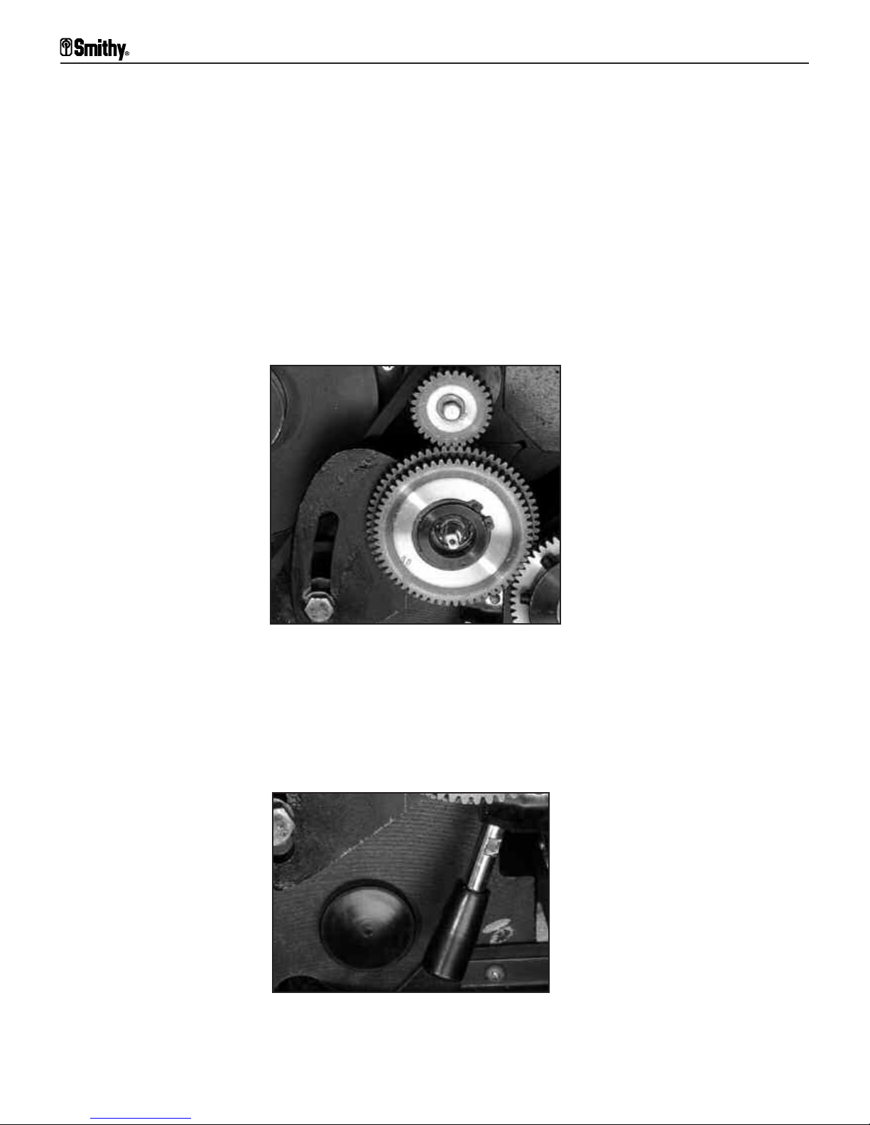
Step 3: If changing the gear set-up is necessary to achieve the desired thread
pitch, follow the procedure under the title “Changing Gears” in the next section.
Changing Gears
Step 1: The A gear is secured with a bolt and washer assembly and the
location is fixed. To remove the gear remove the bolt and washer.
Step 2:The B and C gears share the same shaft and are secured with a snap
ring. Remove the snap ring from the shaft to remove the gears.
Step 3: Place the proper gear in the A position for cutting the desired thread
pitch. Reinstall the washer and bolt.
Step 4:The shaft for the B/C gears mounts on a slotted plate to adjust for the
di
f
f
er
ent diameters of the gears. There are two flats on the end of the shaft to
loosen and tighten the assembly to allow for adjustment. Adjust the B/C gear
shaft as needed to accommodate the B and C gears needed for cutting your
desir
ed thr
ead pi
tch.
Figure 10.3 Make certain that your gears are properly set-up
to obtain the desired thread pitch
A
B
C
Figure 10.4 Inch/metric Selector located inside the pulley box
Granite 1300 Series Operator’s Manual
10-3
For
Assistance: Call
Toll Free 1-800-476-4849
Page 82

Step 5: Loosen the hex head bolt. This allows the assembly to drop down.
Step 6: Position the installed B/C gear unit to mesh with the D gear.
Step 6: Rotate the gear assembly until the B gear meshes with the A gear.
Lock the assembly in place by tightening the hex head bolt.
The hex head bolt also tensions the speed reduction pulley support arm. Be
sure the belts are in the appropriate position before tightening the hex head
bolt.
Cutting Inch Threads
Step 1: S
elect the desired thread pitch that you wish to cut from the chart
located on the headstock of the Granite 1300 series lathe-mill-drill.
Step 2: Engage selector levers (1-7) and selector lever (I-III). Remember, you
can use the jog knob located on the right side of the gear box to help align the
gears if the levers are difficult to engage.
Step 3: Check the gear set
-up inside the pul
ley box to confirm the gearing is
set-up correctly to cut your desired thread pitch. If the gears are not correct,
change gears using the previous procedure.
NOTE:
The default factory setting is for cutting inch, SAE, threads.
Step 4: Confirm that your bel
ts inside the pulley box ar
e properly set-up to
reach the recommended spindle speed for cutting your work piece material with
your specific cutter.
Step 5: Set your compound angle toolpost to 29-1/2º and install the E8
carbide bit that came with your machine.
Step 6: I
nside the pul
ley box at the left lower side of the gear cluster is the
inch/metric lever
, which must be pushed away from you for inch threading.
Step 7: Tu rn y ou r m ac hi ne o n a nd ad j us t va ri ab le s peed to the reco mm ende d
speed.
Step 8: Once you have made all of your tooling and machine settings, you are
ready to begin the first pass. Set the dials on the compound angle toolpost and
cross-slide table to zero. Move the compound angle toolpost into the desired
position and feed the cutter into your workpiece using the small CATP feed
handle. W
atch the thr
eading dial rotate until one of the numbers is just about
to the reference mark. At this point apply firm constant downward pressure on
the half-nut engagement lever until you feel the lever drop into position and the
carriage begins to move. (More information to follow on the threading dial.)
10: Threading
10-4
Or V
isit www
.smithy.com
Page 83

Step 9: When you reach the end of the first cut, lift up on the half-nut
engagement lever, back the cutter out using the CATP feed and return the
cutter to the starting point.
Step 10: Feed the cutter in the desired amount for the next cut, wait for the
same number as before to come up on the dial and engage the half nut.
Continue making passes until you have completed the full depth of cut.
Using the Threading Dial to Cut Inch
Threads
The threading dial is used for cutting inch threads only. Special procedures for
cutting metric threads can be found in the section under “ Cutting Metric
Threading” on the next page.
The thr
eading dial is a mechanical indicator f
or engaging the cut
ter at the exact
same point for each consecutive pass. The numbers on the dial have no
speci
fic reference to pitch, but they provide a reference point so you can start
at the earliest available point and use the same number again for each
consecutive pass.
Note:
When the carriage is mo
ving and the hal
f nut is engaged, you will notice
that the dial no longer rotates. This is normal.
Figure 10.5 Half Nut Engaged
Figure 10.6 Note the number on the threading dial as your
halfnut engages
Granite 1300 Series Operator’s Manual
10-5
For
Assistance: Call
Toll Free 1-800-476-4849
Page 84

Cutting Metric Threads
Step 1: Select the desired thread pitch that you wish to cut from the chart
located on the headstock of the Granite 1300 series lathe-mill-drill.
Step 2: Engage selector levers (1-7) and
selector lever (I-III). Remember, you can use the jog knob located on the right
side of the gear box to help align the gears if the levers are difficult to engage.
Step 3: Check the gear set-up inside the pulley box to confirm the gearing is
set-up correctly to cut your desired thread pitch. If the gears are not correct,
change gears using the previous procedure.
Step 4: Confirm that your belt set-up inside the pulley box is properly set-up
to reach the recommended spindle speed for cutting your work piece material
with your specific cutting tool material.
Step 5: Set your compound angle toolpost to 29-1/2º and install the E8
carbide bi
t that came with your machine.
Step 6: Inside the pulley box at the left lower side of the gear cluster is the
inch/metric lever, which must be pulled toward you for metric threading.
Step 7: Turn your machine on and adjust the variable speed to the
recommended rpm.
Step 8: Once you have made all of your tooling and machine settings, you are
ready to begin the first pass. Apply firm constant downward pressure on the
hal
f-nut engagement lever until you feel the lever drop into position and the
carriage begins to move.
.
Step 9: Do not disengage the half nut at the end of the pass, stop your
machine and r
ev
erse the f
eed dir
ection. Rotate the handle on the compound
angle toolpost counter clockwise to back out your cutter.
Step 10: Restart your machine and bring the cutter back to is original
position. Stop your machine, reverse the direction again.
Step 11: Feed the cutter in the desired amount for the next cut using the CATP
and r
estart y
our machine. Continue this pr
ocess unti
l y
ou ha
ve reached the
desir
ed depth of cut.
10: Threading
10-6
Or V
isit www
.smithy.com
Page 85

Overview
To ke ep yo ur Smi t hy G r ani t e ma c hin e run nin g at opt im um pe rfor man ce , fo l low
this basic maintenance schedule:
Before Each Use
1. Make sure your work area is clean and free of all obstructions.
2. Clear machine cr
oss-slide table, bed ways and tool post of all chips built
up from your previous job.
3. Oil all oil buttons.
4. Clean tai
lstock barrel taper and mi
ll spindle taper wi
th a clean shop towel.
5. Check the oil site gauge under the lathe chuck and add oil if the level is below the
hal
f
-way point.
6. Check all tooling and holding devices for tightness before you turn on the machine.
7. Check the condi
tion and tension of the driv
e bel
ts.
After Each Use
1. Clean chip build up from machine.
2. B
rush chips off the longitudinal feed screw.
3.Remove any excess cutting fluid that may have accumulated on the
machine.
4.Apply protective oil coating to all bare metal surfaces that may rust or
corrode.
11
Machine Maintenance
Schedule
Do not clear chips by hand. Metal chips are very sharp and can
easily cut your hand. Use a brush or shop vaccum to clear chips.
CAUTION
11-1
For
Assistance: Call
Toll Free 1-800-476-4849
Page 86

10 Hours (Daily)
1. Clean chip build up from machine.
2. Brush chips off the longitudinal feed screw.
3. Check the oil site gauge under the lathe chuck and add oil if the level is below the
half-way point.
4. Oil all oil buttons
25 Hours (Monthly)
1. Check the oil site gauge under the lathe chuck and add oil if the level is below the
half-way point.
2. Oil all oil buttons
3. Apply a light coating of oi
l to the outside of the mill spindle and the top of the mi
ll
spindle splines.
4. Lubricate the change gears in the lathe pulley box with an aerosol chain lubricant.
5. Lubricate the inside of the quick change gearbo
x wi
th an aerosol chain lubricate
by spraying through the openings in the front of the gearbox.
6. Remove and clean the lathe chuck and the spindle nose. Lubricate the chuck and
the cam locks with oil.
7. Check all gib adjustments.
8. Check and adjust backlash as necessary.
9. Check the condition of all drive belts and replace if necessary.
100 Hours (Yearly)
1. Change oil in the headstock.
2. Remove the X and Y-Axis gibs and clean with solvent. Coat gibs with way
oil and reinstall.
11: Maintenance Schedule
11-2
Or V
isit www
.smithy.com
Page 87

Powerfeed and Thread Cutting
1. Powerfeed does not move carriage
Cause Solution
• Carriage locked • Unlock carriage
• Speed selector not engaged • Select speed I or II or III, engage
drive selector
• Sheared pin • Replace pin
• Gears not meshing or teeth missing • Check gears and adjust
• Inch/metric lever in neutral • Engage fully
2. Cut is not smooth
Cause Solution
• T
ool dull • Sharpen or r
eplace tool
• Tool not on center • Center tool (shim, if needed)
• Tools not mounted tightly in post • Remount tools
• Cross-sl
ide gibs to bed and base loose • Adjust gibs
• Gibs in toolpost loose • Adjust gibs in toolpost
• Tool turret not tight • Tighten toolpost
• Feed r
ate too fast • Choose correct setting
• Gear loose • Tighten gears and posts
3. Thread is not smooth
Cause Solution
• T
ool dul
l
• Sharpen tool
• Tool not centered • Center tool
• Tools not mounted tight in post • Remount tool
• Cross-slide gibs to bed and base loose • Adjust gibs
• Gibs in compound loose • Adjust gibs
• Tool turret not tight • Tighten toolpost
• Gears loose
• Tighten gears and posts
4. Tools is not cutting “on thread”
Cause Solution
• P
owerf
eed sl
ipping
• Engage halfnut fully
• Clutch slipping • Tighten screws (6)
12
Troubleshooting
12-1
For
Assistance: Call
Toll Free 1-800-476-4849
Page 88

Carriage/Milling Table
1. Table won't move
Cause Solution
• Table locks engaged • Loosen locks
• Gibs too tight • Loosen gibs
2. Horizontal and vertical movement in cross-slide table
Cause Solution
• Carriage gib improperly adjusted • Adjust carriage gib
• Table gib improperly adjusted • Adjust table gib
3. Carriage moves smoothly in only one direction
Cause Solution
• Debris on w
ay or gib • R
emove debris
• Burr on gib • Remove burr with fine file
• Gib improperly tensioned • Loosen gib and re-tension
• One or more wipers mounted too low • R
eposition wiper(s)
4. Cross-slide handwheel turns during cutting operations
Cause Solution
• Cr
oss-slide brass nut worn • Tighten or replace brass nut
• Carriage lock not tight • Tighten carrriage locks
• Gibs too loose • Readjust gibs
5. Too much backlash in the cross-slide
Cause Solution
• Loose screw • Tighten screw, review how to
eliminate backlash
• Loose brass nut • Put a shim between the stud on
the nut and the side of the hole
• W
orn br
ass nut
• R
eplace br
ass nut or adjust scr
ew
at end of nut
• Excessive space between bearing • Add shim washer and dial
12: Troubleshooting
12-2
Or V
isit www
.smithy.com
Page 89

Lathe Turning
Cause Solution
• Tool dull • Sharpen or replace tool
• Tool not ground properly • Regrind tool
• Tool at wrong angle • Correct tool position
• Tools not held tightly • Tighten toolholder
• Wrong cutter for material • Use correct cutter
• Cutting speed incorrect • Increase or reduce speed
2. Work has unwanted taper
Cause Solution
• Work improperly aligned • Realign centers on work
• Debris in spindle, setup, or tools • Clean and reset setup, work, or
tool
• Offset tailstock incorrectly positioned • Correct position of tailstock
• Spindle bearings loose
• Tighten taper bearings to return to
al
ignment, replace spindle
bearings
3. Machine vibrates
Cause Solution
• Work mounted wrong • Remount work
• Speed too high • Reduce Speed
• T
oo much pressure at tailstock • Reduce pressure and increase
lubrication
4. Work stops turning but machine continues to run
Cause Solution
• W
ork not mounted secur
ely
• R
emount work
• Tools forced into work/ excessive cut • Reduce force on tools
• Belts slipping • Tension belts, use belt dressing, or
replace belts
5. Diameter of work is not consistent
Cause Solution
• Too much flex in workpiece • Use a follow rest, use tailstock
center
• T
oo much flex compound r
est,
• Tighten gibs, clean w
ays
cr
oss sl
ide, or carriage
Granite 1300 Series Operator’s Manual
12-3
For
Assistance: Call
Toll Free 1-800-476-4849
Page 90

6. Too much backlash in the compound
Cause Solution
• Loose spanner nuts • Tighten spanner nuts
• Worn Nut • Replace nut
7. Machine slings oil from behind the chuck or in belt box
Cause Solution
• Oil reservior overfilled • Check oil lever
• Worn oil seal • Replace felt in seal
Milling
1. Tool chatter
Cause Solution
• Gibs too loose on cr
oss slide, • R
eadjust gibs
compound, or carriage
• Unused feeds not locked • Lock all axes but the one moving
• Millhead not lock
ed • Lock millhead
• Qui
ll too loose • Tighten quill lock
• Tool not on center • Center tool
• Improper tool shape, tool dull • Reshape, sharpen, or replace tool
• Feed too light or slow • Adjust feed rate
2. Depth of cut is not consistent
Cause Solution
• Qui
l
l mo
ving
• Lock quill
• Setup wrong • Make sure setup is parallel to
table
Drilling
1. Hole is off center or bit wanders
Cause Solution
• Bit dull • Use sharp bits
• Bit not mounted correctly in chuck • Remount tool
• B
i
t bent
• R
eplace bi
t
• Chuck loose in spindle
• R
emount chuck on arbor
• Drawbar not secured • Tighten drawbar
• Debris on spindle • Clean debris and arbor and
remount tool
• B
earing loose or worn
• Tighten or r
eplace bearings
12: Troubleshooting
12-4
Or V
isit www
.smithy.com
Page 91

• Cutting too fast • Reduce speeed
• Incorrect bit • Use correct bits
• No pilot hole • Drill small pilot hole
2. Entrance hole is out of round
Cause Solution
• Bit dull • Use sharp bit
• Incorrect drill bit • Use correct drill bit
3. Bit turns erratically or stops
Cause Solution
• Bit fed into work too fast • Reduce feed rate
• Belts slipping • Reduce feed rate, re-tension belts
4. Chuck is difficult to tighten or loosen
Cause Solution
• Chuck sticking
• Apply lubricant
• Debris in chuck • Clean chuck
5. Chuck wobbles
Cause Solution
• Chuck loose on arbor • Clean arbor and remount
• Drawbar not tight • Clean spindle and r
eplace drawbar
Drive System
1. Turn on the machine and nothing happens
Cause Solution
• Breaker Blown • Re-set circuit breaker
• Machine unplugged
• Plug in the machine
• Loose electrical connections • Tighten wiring connections
• Electrical components bad
• Replace defective parts
2. Motor and pulleys turn, but not lathe or mill
Cause
Solution
• Mill or lathe not selected • Select proper function
Granite 1300 Series Operator’s Manual
12-5
For
Assistance: Call
Toll Free 1-800-476-4849
Page 92

Motor
How to check a Motor
Get a car battery and attach the two wires coming from the motor to the terminals of the
battery. If the motor runs, the motor is okay, if not it needs to be replaced.
Uncscrew brush caps and inspect the brush carbon, spring and wire. If damaged or worn
out replace it.
Chuck and Accessories
If the chuck does not seat properly.
Adjusting the chuck mounting studs
The D1-4 mounting system used on all Granite machines consists of three adjustable
studs mounted on the chuck and thr
ee rotating cam locks on the spindle flange. This is
a very fast and accurate method of chuck mounting; however, there are some
adjustments to be made to insure optimum fit and accuracy.
Removing the chuck
1. The first step in removing the chuck is to place a piece of wood on top of the machine
bed underneath the chuck. This will protect the bed if the chuck accidentally slips out of
your hand and falls onto the machine.
2. There is an alignment mark on each cam and on the spindle flange adjacent to each
cam. Using the chuck key, turn the cam counter clockwise until the two marks align with
each other as shown below.
3. Position all three cams in the unlocked position, put your right hand under the chuck
for support and tap the chuck with a block of wood to break it loose from the spindle.
Spindle
Flange
Unlocked
D1-4 Camlock
Tooling
Cam in Unlocked Position
Spindle
Flange
Locked
D1-4 Camlock
Tooling
Cam in Locked Position
Figure 12.1 D1-4 Lathe Chuck in Locked & Unlocked Position
12: Troubleshooting
12-6
Or V
isit www
.smithy.com
Page 93

4. Inspect the mating surfaces on the end of the spindle and the back of the chuck for
burrs or foreign matter. Clean and deburr these areas as necessary.
Installing and Adjusting the chuck
1. Make sure that the cams are aligned in the unlocked position and slide the chuck
onto the spindle.
2. Turn each cam clockwise to lock the chuck in place.
3. Each cam should turn between 140o to 180oof a turn to lock correctly. See the diagram below.
4. If the cam turns less than one fourth of a turn, it will be necessary to remove the
chuck and adjust the corr
esponding chuck stud.
5. Before removing the chuck, mark each location
on the chuck that will need
adjusting.
6. Remove the chuck and place it face down on a work surface.
7. There is a locking screw along side each chuck stud. Remove the locking screws for
the studs that need adjusting.
8. Unscrew the studs one turn and install the locking screws.
Prefered locking area
Stud
Lock Screw
Figure 12.2 Locking area positon
Figure 12.3 Back of the chuck
Granite 1300 Series Operator’s Manual
12-7
For
Assistance: Call
Toll Free 1-800-476-4849
Page 94

9. Install the chuck and check the cam rotation. Repeat as necessary.
Since there are three studs and cam mounts on the chuck, there are three possible
position that the chuck may be mounted. You will find that one of these positions will be
slightly more accurate than the others. Try the chuck in all three possible positions. Once
the most accurate position is determined, mark the chuck and spindle flange so that the
chuck can be installed in the same position each time that it is mounted onto the
machine. This is best done by putting a punch mark on the chuck and a corresponding
mark on the spindle flange.
This next step is only for the 3-jaw self centering chuck.
Mark each of the three jaws, and the slot it is in. Remove the jaws, and keeping them
in the same order, reinsert them into the next slot over making sure the scroll plate
engages the first thread on the first jaw. Try the jaws in all three positions; one should
be more accurate than the other two.
Leadscrew
Having trouble on the leadscrew backlash particularly on engaging the half
nut?
Leadscrew Backlash Adjustment
Excessive backlash in the longitudinal feed can come from two places:
1. The fit of the longitudinal feed screw to the right hand mounting trestle.
2. The fi
t of the half nut to the feed screw.
Screw to mount backlash
Engage the half nut lever. Slowly turn the longitudinal feed screw clockwise as viewed
from the right end of the machine and watch the gap between the dial and the feed screw
mounting tr
est
le. R
ev
erse the dir
ection y
ou are turning the feed screw and see if the gap
increases slightly. If so then there is some play in the mounting. To reduce the play,
accomplish the following.
1. Remove the bolt/ washer from the right end of the longitudinal feed screw.
2. Unscr
ew the handle f
r
om the end of the f
eed screw.
3. Using a punch and a small hammer, tighten the spanner nut about one eigth of a turn
and recheck the play in the screw.
4. If the pla
y is ac
ceptable, r
eplace the handle and retaining bolt. If more adjustment is
needed, r
epeat the step abo
ve.
12: Troubleshooting
12-8
Or V
isit www
.smithy.com
Page 95

Half nut to screw backlash
Worn threads on the half nut can cause ex
cessiv
e backlash in the longitudinal direction.
Half nuts are made of brass and do wear out over a period of time. The only fix for a
worn half nut is to replace the worn nut with a new one.
Crossfeed Backlash Adjustment
Excessive backlash in the crossfeed can be coming from three different places:
1. The fi
t of the crossfeed screw to the front screw mount.
2. The fit of the crossfeed screw into the brass crossfeed nut.
3. The fit of the brass crossfeed nut into the carriage casting.
There are adjustments for each of the above areas. Before making any adjustments to
the cr
ossf
eed scr
ew system, i
t is r
ecommended that al
l the gibbs on the table and
carriage system be check
ed and adjusted as per the owners’ manual.
Crossfeed Screw To Front Mount
Slowly turn the cr
ossf
eed handle clockwise and w
atch the gap between the dial and the
front screw support mount. Change directions and note if the gap increases slightly. If so
this is a sign that there is some play in the mounting. To reduce this play, follow the
procedure below.
1. Loosen the two nuts that hold the cr
ossf
eed handle on the end of the scr
ew
.
2. Tighten the inner nut slowly whi
le checking the ease of movement of the crossfeed
Lead Screw & Dial
Mounting Trestle
Spanner Nut
Handwheel
Retaining Bolt &
Washer
Figure 12.4 Parts of the Handwheel
Granite 1300 Series Operator’s Manual
12-9
For
Assistance: Call
Toll Free 1-800-476-4849
Page 96

handle. When the screw starts to get hard to turn, loosen the nut slightly so the screw
turns free.
3. Hold the inner nut in place and tighten the outer nut against it to lock the nuts in
position.
4. Recheck the backlash.
Crossfeed Screw to Brass Nut & Nut to Carriage (Locking Bolt)
If there is still an excess of backlash after the above adjustments are made, the play will
be either between the crossfeed screw and the brass nut or between the brass nut and
the carriage. The fol
lowing pr
ocedure covers both adjustments at the same time:
1. Remove the crossfeed screw rear support.
2. Loosen the Allen head bolt that locks the brass nut into the carriage.
3. Crank the crossfeed table toward the operator side of the machine. Watch under the
table from the backside and stop before the crossfeed screw comes out of the brass nut.
Figure 12.5 Crossfeed Screw Parts
Figure 12.6 Crossfeed Table Cross Section
Handle
Inner & Outer
Nuts
Dial
Support
Note: Watch for gap in this area
Crossfeed
Table
12: Troubleshooting
12-10
Or V
isit www
.smithy.com
Cross-slide table
Cross-slide screw
2 Piece Brass Nut
Adjusting Screws
Saddle
Locking Bolt
Page 97

4. Slowly tighten the four adjusting screws on the brass nut, one at a time, until a slight
drag is felt while turning the crossfeed handle.
5. Install the rear crossfeed support and tighten the locking bolt for the brass nut.
6. Recheck the backlash on the crossfeed.
If you find that the four adjusting screws are not staying in place, you can use a small
amount of a thread-locking compound to keep the screws tight.
Granite Series Leadscrew Handwheel Fabrication
& Installation (Earlier Machines)
Purchase part # G91027 or use the instructions below.
Installation of a handwheel to the right end of the leadscrew will allow a more precise
lateral feeding of the carriage travel than is now possible using the carriage feed handwheel. The following is a simple handwheel plan that can be made using the Granite
machine. The wheel portion can be made from a piece of mild steel, aluminum, or cast
ir
on. The handle portion should be made of mild steel.
Hole is drilled & tapped to match
the thread of the handle that was
selected. The handle may be
fabricated from scratch or
purchased already made.
Center hole drilled 27/64
and threaded M12 x 1.25
Handwheel dimension - 85mm
Diameter - 9mm
9mm long & threaded to match the
small hole in the handwheel
Diameter &
length of the handle
your preference
Screw the handwheel on the end of
the leadscrew. Install a bolt &
fender washer into the 5/16 x 24
hole that is in the end of the
leadscrew to hold the handwheel
in place. Screw the handle into the
handwheel & tighten into place.
Figure 12.7 Crossfeed Table Rear View Cross Section
Figure 12.8 Handwheel Fabrication & Installation
Granite 1300 Series Operator’s Manual
12-11
For
Assistance: Call
Toll Free 1-800-476-4849
Saddle
Brass Nut
Adjusting Screws
Table view from rear of
machine.
Page 98

Note:
If you have an older Granite model, the end of the lead screw may not be drilled
and tapped. This is a very simple process. You will need a 5/16 x 24 tap, a 17/64 or a “I”
drill bit, and an electric hand drill. Set up your machine on the slow speed pulley, full RPM,
with leadscrew turning counter clockwise as viewed from the right end and the gearbox
set on 1 and “I”. By having the leadscrew turning as well as the drill, the drill bit will
center itself and go straight down the center of the lead screw. Drill the hole about 5/8
inch deep. Tap the hole with the 5/16 tap. Do not forget to use oil when drilling and
tapping.
NOTES:
12: Troubleshooting
12-12
Or V
isit www
.smithy.com
Page 99

Granite 1324 Series Machine
General Specifications
General Dimension: 39” height X 46” length X 22-1/2” width
Machine Weight: Shipping 770 lbs, Machine 661 lbs
Crate Size: 49-1/2” X 22-3/4” X 44”
Footprint (static): 48” X 36”
Footprint (operating): 72-1/2” X 45-1/4”
T-Slot Size: 7/16”
Spindle Accuracy TIR: 0.00078”
Powerfeed (X-Axis): Yes
Powerfeed (Y-Axis): Yes
Powerfeed (Z-Axis): No
Table Siz
e: 6-3/4” X 17-3/4”
Threading Dial: Yes
Lathe Specifications
Distance B
etween Centers: 24”
Dial Calibration on Crossfeed: 0.001”
Dial Calibration on Toolpost: 0.001”
Dial Calibr
ation on Leadscrew: 0.001”
Dial Calibration on Tailstock: 0.001”
Dial Calibration on Longfeed Rack: 0.01”
Headstock Taper:
MT4
Lathe Chuck- Max. diameter workpiece: 6”
Lathe Chuck- Min. diameter workpiece: 1/8”
Lathe Chuck Bore: 1.6”
Lathe Chuck Diameter: 6”
Lathe Chuck Mount: D1-4 Camlock
Lathe Chuck Type: 3 Jaw Self Centering
Spindle B
or
e:
1.125”
Spindle Speeds: Variable (Range 0-2800 RPM)
X-Axis Travel (w/ tailstock installed): 20”
Y-Axis Travel: 7-5/8”
Feed Rate (X-Axis): 0.003”- 0.020”
Feed Rate (Y-Axis): 0.001”- 0.006”
T
ai
lstock Of
f
set:
19/32”
Tailstock Barrel Travel: 3”
Tailstock Taper: MT3
Swing Over Bed: 13”
Swing Over Work Table: 7-1/2”
Threads:
S
AE 7-52 TPI
Toolbit Siz
e:
1/2”
Toolpost Travel: 3-3/16”
13
Machine Specifications
13-1
For
Assistance: Call
Toll Free 1-800-476-4849
Page 100

Mill Specifications
Column Diameter: 3-3/16”
Dial Calibration Drill-Coarse Feed: 0.05”
Dial Calibration Mill-Fine Feed: 0.001”
Drawbars Size (included): 7/16”
Drill Chuck Size (included): 5/8”
Drill Chuck Arbor Size (included): R-8/JT3
Head Rotation: 360 Degrees
Quill Diameter: 2-3/4”
Quill Travel: 4-7/8”
Spindle Taper: R-8
Spindle to Table Distance (min-max): 4” to 13-3/8”
Tool Size Limits: 1”
X-Axis Travel: 9-1/2”
Y-Axis Travel: 7-5/8”
Head Travel (Z-Axis): 4-3/8”
Feed Rate (Y-Axis): 0.001”- 0.006”
Feed Rate (X-Axis): 0.003”- 0.020”
Spindle Speeds: Variable (Range 0-2800 RPM)
Spindle Center to Front of Chuck:
GN Classic: 4-5/8”
GN-MAX & GN-IMX: 8-1/2”
Spindle Center to Lathe Spindle Flange:
GN Classic: 7-1/4”
GN-MAX & GN-IMX: 11-1/4”
Spindle Center to Support Column:
GN Classic: 9-1/2”
GN-MAX & GN-IMAX: 13-3/8”
Electrical Specifications
Amperage:
GN Classic & GN-MAX:
15 amps
GN-IMAX: 8-10 amps
Horsepower:
GN Classic: 1.5 HP
GN-MAX & GN-IMX: 2.0 HP
Motor Type:
GN Classic: D/C Variable Speed
(P
ermanent Magnet)
GN-MAX & GN-
IMX:
D/C Variable Speed
(Brushless Servo)
Voltage:
GN Classic & GN-MAX: 110 Volts A/C
GN-
IMX:
220 V
ol
ts A/C
Phase:
Single
Recommended Oil for Lubricant
For Gear Box: SAE30 weight non-detergent
oil or 30 weight compressor oil
For External :
R
egular Oi
l
For Cleaning:
Noncorrosive Kerosene or
Whi
te Mineral Spirits or even
WD-40
13: Machine Specifications
13-2
Or V
isit www
.smithy.com
 Loading...