

Page 1

EZ-TROL II CONTROL SYSTEM
USER’S GUIDE
VERSION 1.1
2009
Page 2

SmithyCNC EZ-Trol II Control System User’s Guide
SmithyCNC (Smithy Co.)
170 Aprill Dr., Ann Arbor, Michigan
USA 48103
Toll Free Hotline: 1-800-476-4849
Fax: 1-800-431-8892
International: 734-913-6700
International Fax: 734-913-6663
www.smithycnc.com
Copyright © 2009 SmithyCNC &
All rights reserved. No part of this manual may be reproduced or transmitted in any form by any means,
electronic, mechanical, photocopying, recording, or otherwise, without prior written permission of Smithy Co.
For information on getting permission for reprints and excerpts, comments, or suggestions, contact
info@smithy.com
While every precaution has been taken in the preparation of this manual, Smithy Co. shall not have any
liability to any person or entity with respect to any loss or damage caused or alleged to be caused directly or
indirectly by the instructions contained in this manual or by the computer software and hardware products
described herein. Please see section on warranty and safety precautions before operating the machine.
Printed and bound in the United States of America
Smithy Co.
Page 3

TABLE OF CONTENTS
1 | INTRODUCTION . . . . . . . . . . . . . . . . . . . . . . . . . . . . . . . . . . . . . . . . 1
Development Process . . . . . . . . . . . . . . . . . . . . . . . . . . . . . . . . . . . . 1
Four Steps of Machining. . . . . . . . . . . . . . . . . . . . . . . . . . . . . . . . . . 1
Organization of this Manual . . . . . . . . . . . . . . . . . . . . . . . . . . . . . . . 2
Questions? . . . . . . . . . . . . . . . . . . . . . . . . . . . . . . . . . . . . . . . . . . . . . 2
2 | SMITHYCNC SYSTEM WARRANTY . . . . . . . . . . . . . . . . . . . . . . . 3
3 | SAFETY . . . . . . . . . . . . . . . . . . . . . . . . . . . . . . . . . . . . . . . . . . . . . . . . 5
4 | CONTROL BOX INSTALLATION &
COMPONENT IDENTIFICATION
. . . . . . . . . . . . . . . . . . . . . . . . . . 7
Overview . . . . .
Wiring the Smithy EZ-Trol to the Bedmill. . . . . . . . . . . . . . . . . . . . 7
Installing the monitor, keyboard & mouse . . . . . . . . . . . . . . . . . . . 8
Control System Components & Function . . . . . . . . . . . . . . . . . . . . 8
Basic Electrical Components & Function. . . . . . . . . . . . . . . . . . . . 9
5 | CONNECTING EZ-TROL II . . . . . . . . . . . . . . . . . . . . . . . . . . . . . . 11
Connecting the EZ-Trol II Control Box to the Bed Mill . . . . . . . 11
Connecting the EZ-Trol II to the CNC 622 Bed Mill . . . . . . . . . . 12
Connecting the EZ-Trol II to the CNC 924 Lathe . . . . . . . . . . . . . 13
6 | LAUNCHING EZ-TROL II. . . . . . . . . . . . . . . . . . . . . . . . . . . . . . . . 14
Booting-up EZ-Trol II Control System . . . . . . . . . . . . . . . . . . . . . . 14
7 | NAVIGATING EZ-TROL . . . . . . . . . . . . . . . . . . . . . . . . . . . . . . . . . 16
The Four Tabs . . . . . . . . . . . . . . . . . . . . . . . . . . . . . . . . . . . . . . . . . 16
Auto Tab . . . . . . . . . . . . . . . . . . . . . . . . . . . . . . . . . . . . . . . . . . . . . . 16
Manual Tab . . . . . . . . . . . . . . . . . . . . . . . . . . . . . . . . . . . . . . . . . . . 17
Settings Tab . . . . . . . . . . . . . . . . . . . . . . . . . . . . . . . . . . . . . . . . . . . 18
Wizards Tab . . . . . . . . . . . . . . . . . . . . . . . . . . . . . . . . . . . . . . . . . . . 18
Navigating EZ-Trol II . . . . . . . . . . . . . . . . . . . . . . . . . . . . . . . . . . . . 18
Backlash Compensation . . . . . . . . . . . . . . . . . . . . . . . . . . . . . . . . . 19
. . . . . . . . . . . . . . . . . . . . . . . . . . . . . . . . . . . . . . . . . . 7
8 | HOMING & SETTING OFFSETS. . . . . . . . . . . . . . . . . . . . . . . . . . 20
Overview . . . . . . . . . . . . . . . . . . . . . . . . . . . . . . . . . . . . . . . . . . . . . . 20
Machine Home Settings . . . . . . . . . . . . . . . . . . . . . . . . . . . . . . . . . 20
Page 4

Initial Machine Homing - one axis at a time . . . . . . . . . . . . . . . . 20
Homing Your Machine on All Axes . . . . . . . . . . . . . . . . . . . . . . . . 22
Limit Override . . . . . . . . . . . . . . . . . . . . . . . . . . . . . . . . . . . . . . . . . 22
Basic G-code . . . . . . . . . . . . . . . . . . . . . . . . . . . . . . . . . . . . . . . . . . 23
Coornidate Systems & Offsets . . . . . . . . . . . . . . . . . . . . . . . . . . . . 26
9 | NAVIGATING THE AUTO TAB . . . . . . . . . . . . . . . . . . . . . . . . . . . 28
Overview . . . . . . . . . . . . . . . . . . . . . . . . . . . . . . . . . . . . . . . . . . . . . . 28
Auto Tab Parts . . . . . . . . . . . . . . . . . . . . . . . . . . . . . . . . . . . . . . . . . 28
Position Area . . . . . . . . . . . . . . . . . . . . . . . . . . . . . . . . . . . . . . . 29
Tool Path Display Area . . . . . . . . . . . . . . . . . . . . . . . . . . . . . . . 29
Pan Across Display Area. . . . . . . . . . . . . . . . . . . . . . . . . . 30
Zoom In or Out on the View . . . . . . . . . . . . . . . . . . . . . . . 30
Rotate Image . . . . . . . . . . . . . . . . . . . . . . . . . . . . . . . . . . . . 30
Command Menu. . . . . . . . . . . . . . . . . . . . . . . . . . . . . . . . . . . . . 30
Open . . . . . . . . . . . . . . . . . . . . . . . . . . . . . . . . . . . . . . . . . . 30
Run . . . . . . . . . . . . . . . . . . . . . . . . . . . . . . . . . . . . . . . . . . . . 30
Pause & Resume. . . . . . . . . . . . . . . . . . . . . . . . . . . . . . . . . 30
Step . . . . . . . . . . . . . . . . . . . . . . . . . . . . . . . . . . . . . . . . . . . 30
Verify . . . . . . . . . . . . . . . . . . . . . . . . . . . . . . . . . . . . . . . . . . 30
Status Block
Feed Override
Speed Override . . . . . . . . . . . . . . . . . . . . . . . . . . . . . . . . . . . . . 31
E-Stop Button . . . . . . . . . . . . . . . . . . . . . . . . . . . . . . . . . . . . . . . 31
Abort . . . . . . . . . . . . . . . . . . . . . . . . . . . . . . . . . . . . . . . . . . . . . . 32
Feed Hold . . . . . . . . . . . . . . . . . . . . . . . . . . . . . . . . . . . . . . . . . . 32
Program Display Window. . . . . . . . . . . . . . . . . . . . . . . . . . . . . 32
. . . . . . . . . . . . . . . . . . . . . . . . . . . . . . . . . . . . . . . . 31
. . . . . . . . . . . . . . . . . . . . . . . . . . . . . . . . . . . . . . . 31
10 | NAVIGATING THE MANUAL TAB. . . . . . . . . . . . . . . . . . . . . . . . 33
Overview
Manual Tab Parts . . . . . . . . . . . . . . . . . . . . . . . . . . . . . . . . . . . . . . . 33
. . . . . . . . . . . . . . . . . . . . . . . . . . . . . . . . . . . . . . . . . . . . . . 33
Position Area . . . . . . . . . . . . . . . . . . . . . . . . . . . . . . . . . . . . . . . 34
Status Block . . . . . . . . . . . . . . . . . . . . . . . . . . . . . . . . . . . . . . . . 34
Jog Area . . . . . . . . . . . . . . . . . . . . . . . . . . . . . . . . . . . . . . . . . . 34
X & Y Axis Positive & Negative Direction. . . . . . . . . . . . 34
Z-Axis Positive &
A-Axis Positive & Negative Direction . . . . . . . . . . . . . . . 35
Speed Area . . . . . . . . . . . . . . . . . . . . . . . . . . . . . . . . . . . . . . . . . 35
Continuous & Incremental Speed . . . . . . . . . . . . . . . . . . 35
Amount . . . . . . . . . . . . . . . . . . . . . . . . . . . . . . . . . . . . . . . . . 36
Feed & Rapid Buttons. . . . . . . . . . . . . . . . . . . . . . . . . . . . . 36
Axis Set-up . . . . . . . . . . . . . . . . . . . . . . . . . . . . . . . . . . . . . . . . . 36
Feed Override . . . . . . . . . . . . . . . . . . . . . . . . . . . . . . . . . . . . . . . 36
Jog Speeds
Spindle Speed Control . . . . . . . . . . . . . . . . . . . . . . . . . . . . . . . 36
. . . . . . . . . . . . . . . . . . . . . . . . . . . . . . . . . . . . . . . . . 36
Negative Direction . . . . . . . . . . . . . . . 35
Page 5

Manual Data Input. . . . . . . . . . . . . . . . . . . . . . . . . . . . . . . . . . . 37
Spindle . . . . . . . . . . . . . . . . . . . . . . . . . . . . . . . . . . . . . . . . . . . . 37
Coolant . . . . . . . . . . . . . . . . . . . . . . . . . . . . . . . . . . . . . . . . . . . . 37
E-Stop . . . . . . . . . . . . . . . . . . . . . . . . . . . . . . . . . . . . . . . . . . . . . 37
Abort . . . . . . . . . . . . . . . . . . . . . . . . . . . . . . . . . . . . . . . . . . . . . . 37
Feed Hold . . . . . . . . . . . . . . . . . . . . . . . . . . . . . . . . . . . . . . . . . . 37
11 | NAVIGATING THE SETTINGS TAB . . . . . . . . . . . . . . . . . . . . . . . 38
Settings Tab Parts . . . . . . . . . . . . . . . . . . . . . . . . . . . . . . . . . . . . . . 38
Editor . . . . . . . . . . . . . . . . . . . . . . . . . . . . . . . . . . . . . . . . . . . . . 38
Tool Table . . . . . . . . . . . . . . . . . . . . . . . . . . . . . . . . . . . . . . . . . 38
Offsets . . . . . . . . . . . . . . . . . . . . . . . . . . . . . . . . . . . . . . . . . . . . 39
Offsets By Random & By Length . . . . . . . . . . . . . . . . . . . 39
Zero All . . . . . . . . . . . . . . . . . . . . . . . . . . . . . . . . . . . . . . . . . . . . 40
Setting-up A Project. . . . . . . . . . . . . . . . . . . . . . . . . . . . . . . . . . . . . 40
12 | NAVIGATING THE WIZARDS TAB . . . . . . . . . . . . . . . . . . . . . . . 41
Overview . . . . . . . . . . . . . . . . . . . . . . . . . . . . . . . . . . . . . . . . . . . . . . 41
Navigation Menu . . . . . . . . . . . . . . . . . . . . . . . . . . . . . . . . . . . . . . . 42
Loaded Wizards List. . . . . . . . . . . . . . . . . . . . . . . . . . . . . . . . . . . . . 42
General Settings . . . . . . . . . . . . . . . . . . . . . . . . . . . . . . . . . . . . . . . . 43
Tool Selection . . . . . . . . . . . . . . . . . . . . . . . . . . . . . . . . . . . . . . . . . 43
Add New Operation . . . . . . . . . . . . . . . . . . . . . . . . . . . . . . . . . . . . . 44
Notes . . . . . . . . . . . . . . . . . . . . . . . . . . . . . . . . . . . . . . . . . . . . . . . 44
Setting-up an Individual Wizard . . . . . . . . . . . . . . . . . . . . . . . . . . 44
13 | UNDERSTANDING G-CODES . . . . . . . . . . . . . . . . . . . . . . . . . . . 51
Overview . . . . .
Why write your own G-code? . . . . . . . . . . . . . . . . . . . . . . . . . . . . 51
Basic G-code Theory . . . . . . . . . . . . . . . . . . . . . . . . . . . . . . . . . . . . 52
Understanding the G-code Program . . . . . . . . . . . . . . . . . . . . . . 53
14 | PREPARING YOUR MACHINE BEFORE OPERATION . . . . . . 58
Overview . . . . . . . . . . . . . . . . . . . . . . . . . . . . . . . . . . . . . . . . . . . . . . 58
Homing the Machine . . . . . . . . . . . . . . . . . . . . . . . . . . . . . . . . . . . . 58
Setting Workpiece Offsets . . . . . . . . . . . . . . . . . . . . . . . . . . . . . . . 58
Populating Tool Table . . . . . . . . . . . . . . . . . . . . . . . . . . . . . . . . . . . 60
15 | ADDING COMPONENTS . . . . . . . . . . . . . . . . . . . . . . . . . . . . . . . 61
Open Architecture Layout. . . . . . . . . . . . . . . . . . . . . . . . . . . . . . . . 61
Upgraded I/O Capacity
To Add a Simple Turn On/Off Program . . . . . . . . . . . . . . . . . . . . . 61
. . . . . . . . . . . . . . . . . . . . . . . . . . . . . . . . . . . . . . . . . 51
. . . . . . . . . . . . . . . . . . . . . . . . . . . . . . . . . . 61
Page 6

To Add More Programming the Machine . . . . . . . . . . . . . . . . . . 62
16 | ELECTRICAL PIN OUTS . . . . . . . . . . . . . . . . . . . . . . . . . . . . . . . . . 63
17 | SCHEMATICS . . . . . . . . . . . . . . . . . . . . . . . . . . . . . . . . . . . . . . . . . 67
SmithyCNC 622 Schematics . . . . . . . . . . . . . . . . . . . . . . . . . . . . . . 68
SmithyCNC 924 Lathe Schematics . . . . . . . . . . . . . . . . . . . . . . . . 71
SmithyCNC 1240 Schematics . . . . . . . . . . . . . . . . . . . . . . . . . . . . . 74
Appendix
A | SETTING TOOL LENGTH OFFSETS
B | FILE SHARING BETWEEN THE EZ-TROL II CONTROL SYSTEM
& WINDOWS PC SYSTEM THAT ARE ON THE SAME
NETWORK
C | BASIC INSTRUCTION FOR CONNECTING EZ-TROL II
TO A WIRELESS NETWORK
. . . . . . . . . . . . . . . . . . . . . . . . . . . . . . . . . . . . . . . . . . . . 76
. . . . . . . . . . . . . . . . . . . . . . . . . . . . 77
. . . . . . . . . . . . . . . . . . . . . . 75
Page 7

1
INTRODUCTION
Thank you for choosing the SmithyCNC EZ-Trol II Control System as the CNC control option for
your SmithyCNC machine.
Smithy’s unique EZ-Trol II system not only opens up the world of machining to you but the world of
small shop manufacturing. The unique EZ-Trol II user interface provides an intuitive step by step
process that makes CNC machining more understandable for the novice and seasoned machinist.
No doubt you are anxious to start making chips fly, but it is important that you to take a few
minutes to read this introduction and understand the development process behind the Smithy
EZ-Trol II Control system.
Once again thank you for choosing Smithy EZ-Trol II.
DEVELOPMENT PROCESS
Smithy Company has been selling machining equipment for over twenty years. Over the years we
have seen increasing interest in low-cost bench-top CNC machines for use in the small shop
environment. The types of individuals that have shown an interest in CNC bench top machining
include home hobbyists, engineers in R & D laboratories, small job, lo-tech tech tranining centers,
shop owners and garage shop entrepreneurs. Individuals from a variety of other industries have
seen the potential of CNC machine tools to get their jobs completed more efficiently.
Historically
usually a limiting factor in small shops and CNC machines have traditionally been expensive. The
most cost effective option for many has been to purchase a manually operated machine and then
retro fit it with a CNC control system. Following this path has left machine owners with no marginal technical support. Not to mention the inordinate amount of time (and patience) it takes to convert a conventional machine to a CNC machine.
With this in mind, our development staff, which includes industry leading machine tool and control
system engineers, worked to develop a control system that would allow small shop machinists to
produce and reproduce parts with lower cost CNC tools.
, finding a good low-cost CNC machining solution has not been an easy task. Money is
ORGANIZATION OF THIS MANUAL
The organization of this manual was constructed from the point of view of a committed but still
learning CNC machinist who is unfamiliar with the EZ-T
chapters will familiarize you with the installation of the EZ-Trol II System and how to navigate the
control system and interface. The remaining chapters are intended to provide you with an overview
of how to use the
rol II control system. Studying the first few
www.smithycnc.com | 1
Page 8

w SmithyCNC EZ-Trol II Control System
control system. Please be sure you are comfortable with the concepts presented before
roceeding to using the control system.
p
QUESTIONS?
gain, thank you for choosing a Smithy product. Contact us if you have any questions not covered
A
in this manual. We can be reached by phone, Monday through Friday 8 AM to 5 PM EST or we can
be reached on the web at
info@smithy. com.
2 | Toll Free 1-800-476-4849
Page 9

2
WARRANTY
Smithy Warranty
SmithyCNC warrants its machines and control systems for a period of one (1) year to the
original purchaser from the date of purchase. If within one (1) year form the date of
purchase a SmithyCNC machine and/or control system fails due to defect in material or
workmanship, SmithyCNC will at their choice repair and/or replace components with new
or remanufactured parts free of charge.
Most warranty repairs and/or replacements are handled routinely, but sometimes request
for warranty service many not be appropriate. This warranty does not apply to defects due
directly or indirectly to misuse, abuse, negligence, accidents, repairs, or lack of routine
maintenance. This warranty is also void if the serial number of the machine or SmithyCNC
control system has been removed or has been altered or modified.
In no event shall Smithy be liable for indirect, incidental or consequential damages for the
sale or use of the product. This disclaimer applies to both during and after the term of this
warranty
.
We do not warrant or represent that the merchandise complies with the provisions of any
law or acts unless Smithy Co. so warrants. In no event shall Smithy's liability under this
warranty exceed the purchase price paid for the product. Legal actions brought against
Smithy Co. shall be tried in the State of Michigan, County of Washtenaw.
Smithy Co. shall in no event be liable for death, injuries to persons or property for
incidental, contingent, special or consequential damages arising from the use of our
products.
This is Smithy Co.’s sole warranty and any and all warranties that may be implied by law,
including any merchantability or fitness, for any particular purpose, are hereby limited to
the duration of this written warranty
This warranty gives you specific legal rights, and you may also have other rights, which
vary from state to state. Some states do not allow the exclusion or limitation of
incidental or consequential damages, so the above limitation or exclusions may not apply
to you.
.
www.smithycnc.com | 3
Page 10

T
elephone Support (Service engineers are available 8 am to 5 pm EST):
Service and Parts
Tel No. 1-800-476-4849
Fax No. 1-734-913-6663
Email Address: sales@smithy.com
International: (734) 913-6700
Software and Programming Consultancy Services
In addition to our customary technical support for the machines and controls, we also
provide technical consulting support to our customers by providing engineering and
G-code programming services. The standard rate for these services is $28.00 per hour. Our
principal objective is to support you and to increase your productivity while reducing the
machining cost. Give us a call for such support as and when required.
Tel No. 1-800-476-4849
Fax No. 1-734-913-6663
Email Address: sales@smithy
.com
4 | Toll Free 1-800-476-4849
Page 11

3
SAFETY
OVERVIEW
This section is the most important section of the manual. Remember safety should always be
priority number one and always let common sense be your guide. The safety rules listed below are
by no way exhaustive; if any questions arise concerning safe operation, consult with the factory
before initiating the operation. Remember the operator of this control system is working with
electrical components and a shock hazard is always present.
The items listed below can cause potential harm to the health of the operator and can result in
serious harm to the machine if the action is not avoided.
1 Power must be shut off before working on any electrical components and control
box elements.
2 The control box should be kept CLOSED at all times, except when maintenance is
required.
3 Protective equipment for eyes, hands or face must be worn while working on
electrical components.
4 When working on exposed energized conductors or circuit parts, trained personnel
must use insulated tools or handling equipment.
5 Do not use flexible cords installed in the control box for raising, pulling or
lowering the control system. All cords should be disconnected first before the
equipment is moved.
6 Exposed cords and electrical connections shall be periodically inspected before
use for external defects.
7 Do not touch any electrical components when wet or in any conductive work
locations.
8 Over current or voltage protection elements of the electrical/control box must not
be changed or removed without factory consultation.
www.smithycnc.com | 5
Page 12

w SmithyCNC EZ-Trol II Control System
9 Only qualified trained personnel should perform maintenance and testing on
electrical circuits and components.
10 Do not run the machine or conduct maintenance operations in an environment
where flammable or explosive materials are present.
11 When testing or adjusting an energized circuit, a rubber mat, duckboard, or other
suitable insulation shall be used underfoot where an insulated deck does not exist.
12 When maintenance is required, make sure the machine is unplugged.
13 Whenever in doubt, consult factory before the any operation is performed.
6 | Toll Free 1-800-476-4849
Page 13
4
CONTROL SYSTEM COMPONENTS
& FUNCTIONS
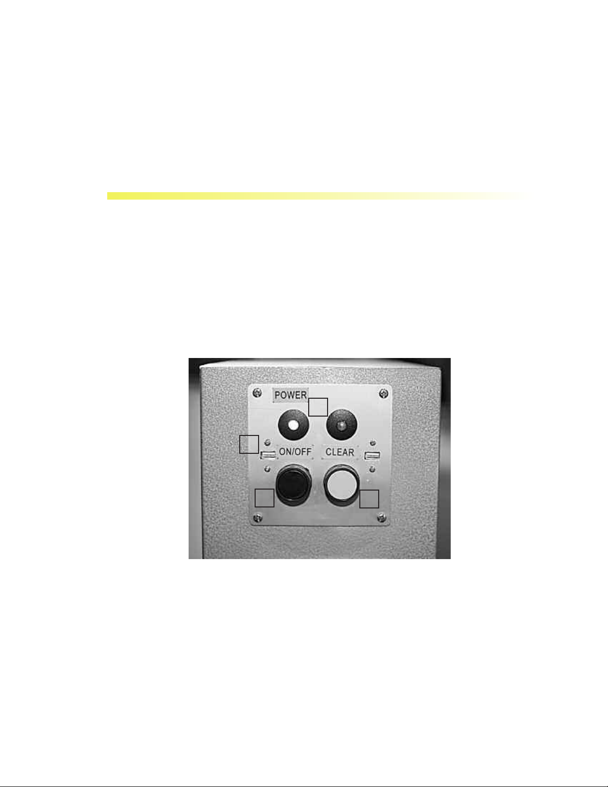
The Smithy EZ-Trol II is equipped with 2 control panels located on the operator’s side of the box
(opposite the side with the control cables.) These switches are identified below and we suggest that
you become familiar with these switches before operating your machine.
COMPUTER CONTROL PANEL
This panel works and functions the same as a personal computer. The panel controls are connected to the motherboard of the control system.
2
1
3
Figure 4.1 EZ-Trol II Computer Control Panel
1. USB Ports (2) - Used for loading programs into the EZ-Trol II system.
2. Power Light – Indicates that the control is turned on.
3. Disk Light – Indicates that a program is reading or writing to the internal solid slate disk.
4. ON/OFF Switch – Turns power on and off to the comtrol.
4
Clear – Restarts (reboots) the contol.
5.
www.smithycnc.com | 7
Page 14

w SmithyCNC EZ-Trol II Control System
E-STOP CONTROL PANEL
1
3
2
Figure 4.2 EZ-Trol II E-Stop Control Panel
1. E-Stop Button – Round red mushroom head push button which when depressed until it latches
will cause the control system to go into emergency stop mode, or defeat any attempt to exit emergency stop mode. This button can be released from it's depressed position by rotating the mushroom shaped actuator.
2. E-Stop Reset – A shrouded blue momentary push button that when depressed and released will
cause the control system to exit emergency stop mode if all the following preconditions are met:
A. The ESTOP Button is released.
B. The HALT/RUN Key Switch is in the HALT position.
C. The CNC control software is running.
D. There are no faults in any monitored internal control system components.
Halt/Run Key Switch – This maintained action, key actuated switch has two positions:
3.
A. HALT: When the key switch is in this position power to the spindle motor drive is disconnected and the control software is switched to “MACHINE OFF” mode which disables axis movement and program execution control commands.
B. RUN: When the key switch is in this position all machine functions are available.
CABLE CONNECTION PANEL
The Smithy EZ-T
machine. You will find the cables packed in with the machine, and labeled for easy connection.
rol II control system comes with all the necessary cables to connect it to your
8 | Toll Free 1-800-476-4849
Page 15
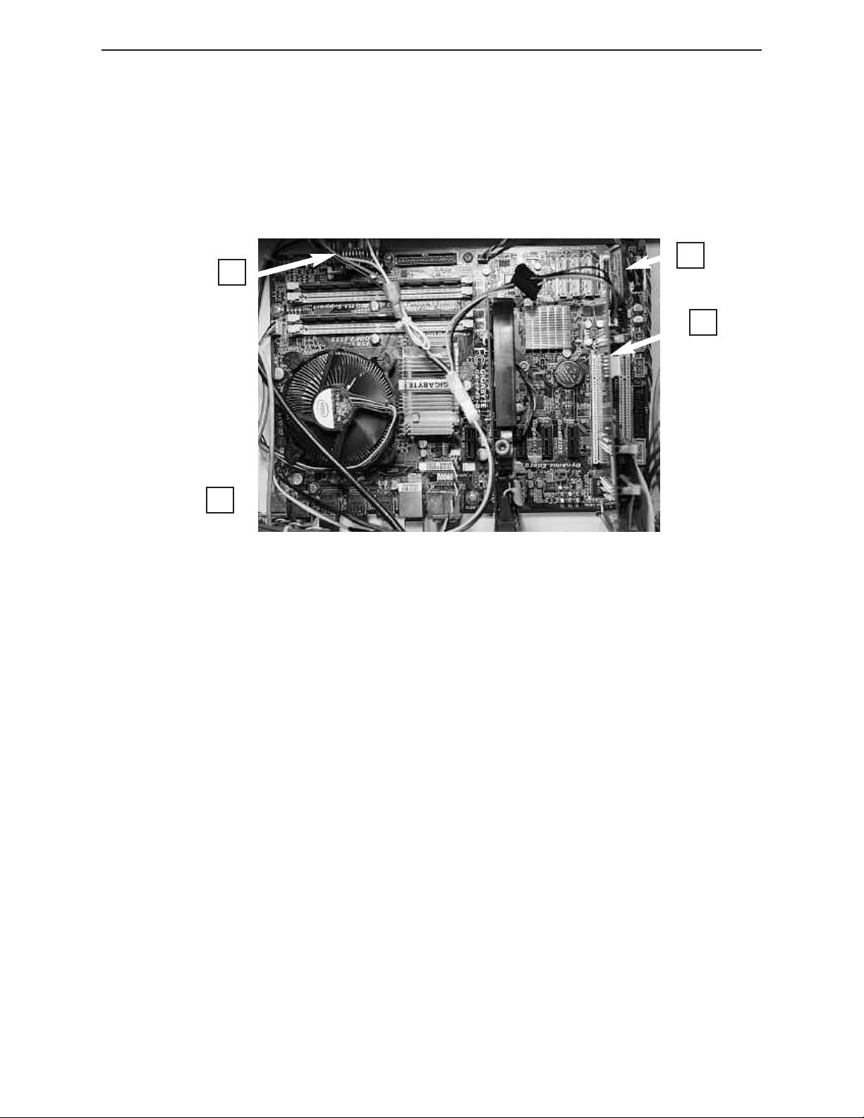
BASIC ELECTRICAL COMPONENTS AND ITS FUNCTIONS
1. Motherboard – Chosen specifically to handle the real time requirements of CNC control prorams for our machines, it has the connections for the keyboard and mouse, plus a D-subminiature
g
ype VGA connection for the monitor. The motherboard uses conductive polymer solid capacitors
t
for durabilty and long life. Intel 45nm CPU chips provide dual core capabilities while using 35% less
power. Along with the power savings of a solid state disk, this system delivers a high performance
computer using a small power supply and generates less waste heat.
3
4
2
1
Figure 4.3 EZ-Trol II
2. MESA Electronics 5I20 Card – A field programmable gate array card that is programmed gen-
erate step pulses, spindle speed control signals, and provide general pupose I/O. It delivers superior quality motion control at high speeds, and makes the graphical user interface more responsive.
This also frees up the main CPU for work on lower frequency but computationally intensive tasks
like trajectory and kinematics calculations. Connecting this outboard “helper chip” to the main
through the high speed, low latency PCI bus back plane delivers better performance than sim-
CPU
ilar systems that use USB, serial port, or Ethernet connections.
3. Compact Flash Card Adaptor – The control system software runs from a solid state disk (com-
pact flash) which greatly reduces power consumption and increases reliability by eliminating moving parts. The CF card simplifies upgrades by allowing the simple exchange of the existing card with
a new card holding file upgrades.
4. DC to DC Converter Power Supply – Converts the 24Vdc control system logic voltage to the
voltages required by the motherboard and CPU. This eliminates the standard PC power supply as a
source of trouble. This power converter has been designed for operation in automotive and industrial environments and simplifies the system power distribution.
5. Isolated I/O Boards – Converts the TTL signals from the MESA S120 Board into 24 Volt com-
patible I/O. All timing critical electrical signals, and all signals that require high fidelity data transmission for proper circuit operation are transmitted in “differential” form over two wire twisted
pair circuits, rather than the typical one wire plus ground “single ended” circuits.
Motherboard
www.smithycnc.com | 9
Page 16

w SmithyCNC EZ-Trol II Control System
a.MESA Electronics 7I47 RS-422 Interface Board (Upper
Board) – Provides 12 RS422 transmitters and 12 RS422 receivers
for differential signaling.
MESA Electronics 7I37 Isolated I/O Board (Lower
b.
Board) – Provides 16 Inputs and 8 Outputs of optically isolated
24 Volt I/O.
Figure 4.5 Isolated I/O Boards
Charge Pump to E-stop – Detects the presence of a signal generated
6.
by the CNC software when it is running. When this signal is not present due
to the CNC control software either not running or not operating correctly,
this module signals an emergency stop.
Figure 4.6 Charged
Pump to E-Stop
7. EMI and RFI Filtering devices - Restricts the undesired propagation of electromechanical and
radio frequency interference produced by the machine’
trol the interference the control system is equipped with both a power line filter module and strategically placed ferrite beads. Twisted pair wiring, shielded cables and attention to wiring layout
inside the control cabinet also reduce undesired emissions.
s spindle motor axis motor drives. To con-
10 | Toll Free 1-800-476-4849
Page 17
5
CONNECTING EZ-TROL II
Smithy lathes and mills are equipped with the required cables and connectors for connecting the
EZ-Trol system to the machine. Instructions for connecting the conrol to each SmithyCNC machine
follows below:
CONNECTING THE EZ-TROL II CONTROL BOX TO THE BED MILL
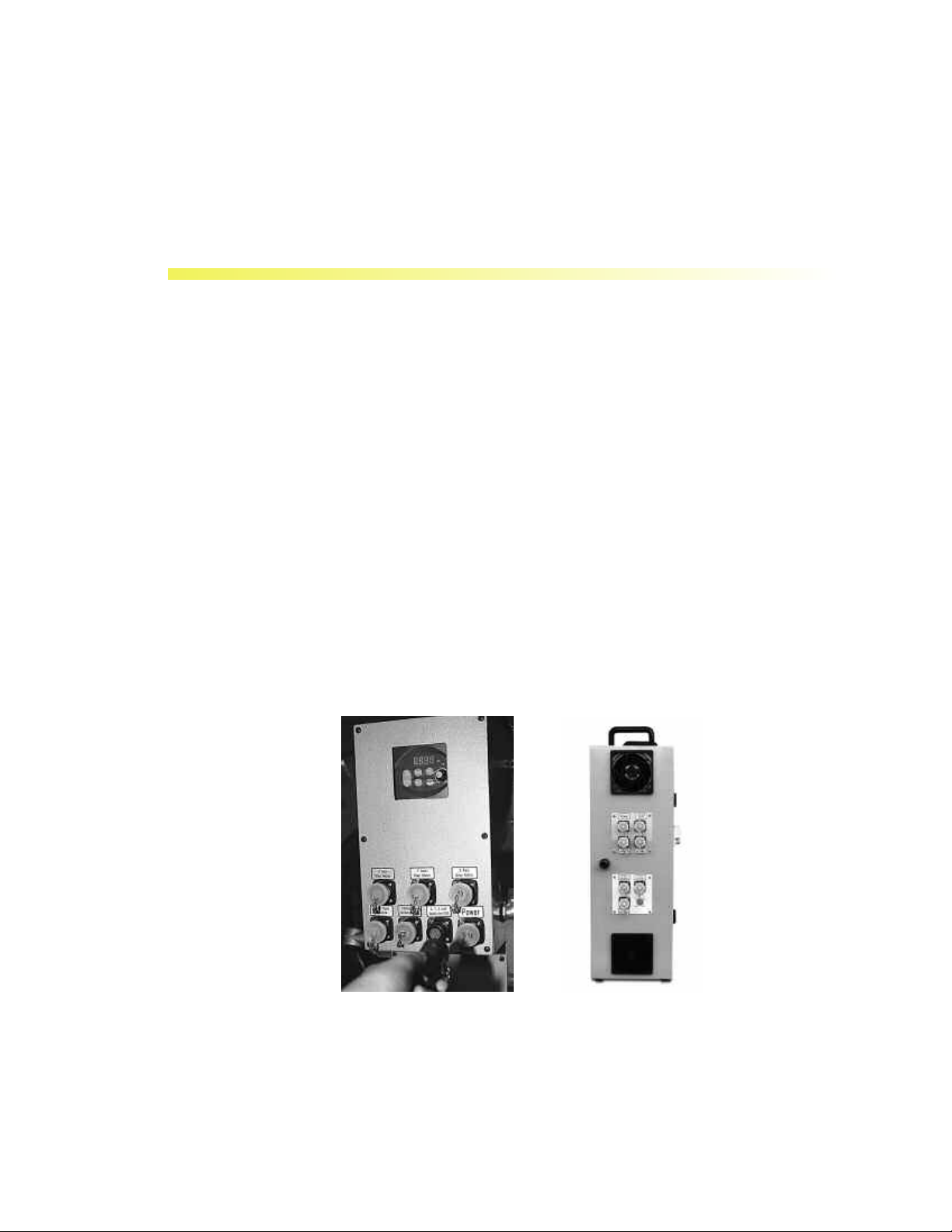
Step 1: Connect the Power Supply Box to the SmithyCNC 1240 Bed Mill
The EZ-Trol II Control Box is shipped with seven (7) 6’ cables that connect the junction box located at the back of the 1240 bed mill to the power supply box. Each cable has identifying tags that
correspond with labels on the junction box and power supply box.
Connect the corresponding plugs, first to the sockets on the junction box on at the back of the bed
mill, and then to the proper sockets on the power supply box. It is advisable to start from the upper
left moving to the right and down.
Please make sure that you have read all the labels before proceeding.
Figure 5.1 1240 Bed Mill Connected to the Power Supply Box
Step 2: Placing the Power Supply Box
The system is designed so you can place the power supply on the floor beside or behind the mill.
The cords are long enough for you to have some flexibility in positioning the box.
www.smithycnc.com | 11
Page 18

w SmithyCNC EZ-Trol II Control System
Be sure to place it in a location that is level and away from potential water exposure. The power
upply box is equipped with handles on the top of the box for easy repositioming.
s
Step 3: Connecting the Power Supply Box to the Control Box
The EZ-Trol II Control System is shipped with the two (2) 6’ cables that connect the CNC 1240
ower supply box to the control box. One cable has a round 31-pin connector and the other has a
p
50-pin connector that matches the long and narrow connection on both the front end of the power
supply box and the rear end of the control box. See image below.
Figure 5.2 SmithyCNC EZ-Trol II Control Box and Power Supply Box
Connect the corresponding plugs on each side securely and you are ready to continue. Please
make sure all threaded connections are tight.
Step 4: Connecting the Keyboard, Mouse and Monitor
The computer motherboard located inside the control box has ports for installing the keyboard,
mouse and the optional Ethernet network connection. Plug the cables into the corresponding sockets for the keyboard and the mouse. The monitor is plugged into the video card on the motherboard.
The monitor power cord can be plugged into any standard receptacle.
Figure 5.3. Keyboar, Mouse and Monitor Plug Layout
CONNECTING THE EZ-TROLL II TO THE CNC 622 BED MILL
The power supply enclosure for the CNC 622 is mounted on the right rear of the column (as you
stand facing the machine). The CNC 622 has the same two cables, with 31 pin and 50 pin
connections, as the 1240 mill. The sockets for connecting the cables are located on the power supply enclosure. Connect the 31 pin and 50 pin cables to the power supply and then to the control
box.
12 | Toll Free 1-800-476-4849
Page 19
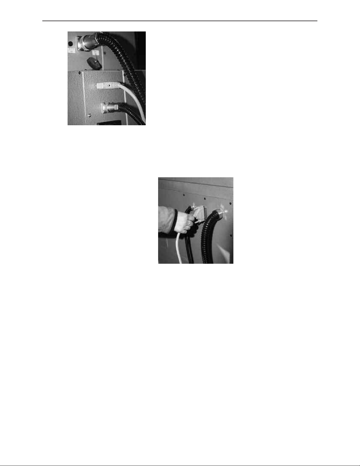
Figure 5.4 SmithyCNC EZ-Trol II Plug Layout for SmithyCNC 622
Bed Mill
CONNECTING THE EZ-TROL II TO THE CNC 924 LATHE
The power supply enclosure for the CNC 924 is in the base of the lathe. The CNC 924 Lathe has the
same two cables as the two mill, plus an additional 9-pin cable for signals from to the spindle
encoder.
Figure 5.5 Connecting the Control Box to the SmithyCNC 924 Lathe
Please make sure that all connections are properly installed. Avoid loose connections that might
cause problems with the operation.
If any labels are missing or removed, plese replace it right away in order to avoid confusion during
re-installation.
If you need help in installation process, call us Toll Free 1-800-476-4849.
www.smithycnc.com | 13
Page 20
6
LAUNCHING EZ-TROL II
BOOTING EZ-TROL II CONTROL SYSTEM
Most of time, you will need to turn on your machine when you launch the EZ-Trol II control system
software. To turn on your machine, please refer to your operator’s manual.
Step 1: Once the machine is turned on, push the control box on/off switch. The green power
indicator light should be on. Make sure that your monitor is plugged on the wall socket and is
properly turned on.
Step 2: Wait for the desktop screen to show up.
Step 3:
Step 4:
Figure 6.1 Booting up EZ-Trol II Screenshot
Step 3: Click on the APPLICATIONS tab on the upper left hand corner of the screen.
Step 5:
Step 4: A dropdown menu will show
Step 5: A new dropdown menu will appear and click on EMC2.
14 | Toll Free 1-800-476-4849
. Click on CNC.
Page 21
Step 6: A welcome screen will appear that will prompt you to choose what kind of machine you are
sing. Click on your machine and the Manual Tab will appear.
u
SmithyCNC
q 622 Bed Mill
240 Bed Mill
q 1
q 924 Lathe
Figure 6.2 EZ-Trol II Configuration Sector
NOTE: You may also create a Desktop Shorcut to easily boot up EZ-Trol II.
Now you are ready to use EZ-Trol II. The opening screen will appear as shown below.
Figure 6.3 EZ-Trol II Opening Page
www.smithycnc.com | 15
Page 22
7
NAVIGATING EZ-TROL II
THE EZ-TROL II TABS
EZ-Trol II’s interface is broken down into tabs. Each tab is given its own section in this manual that
describes the related functions. This chapter will only provide the operator with a brief description
of each tab and the conventions used to navigate the system.
Move from one section to another by left clicking with the mouse on the desired tab. Notice in the
screen below the blue circle located to the left of the word Manual. The blue circle indicates the
active tab. Navigation techniques will be discussed at the end of this chapter
AUTO TAB
The Auto Tab, shown below is the main screen used for executing the parts program. When EZ-Trol
is powered up note that the position coordinates are colored orange which means that the machine
must be homed. How to set-up and home the SmithyCNC machine tools will be discussed in the
next chapter. The functions of the Auto Tab screen will be explained in detail in a later chapter of
this manual.
16 | Toll Free 1-800-476-4849
Figure 7.1 Auto Tab Screenshot
Page 23

MANUAL TAB
he Manual Tab shown above is used to manually jog the machine’s axes. This is also the screen
T
where homing the machine and MDI (manual data input) operations are performed. The functions
of this mode will be explained on a later chapter of this manual.
Figure 7.2 Manual Tab
SETTINGS TAB
The Settings Tab shown in figure below are where the operator defines the work piece offsets. An
operator can also modify a file opened then either save it and send to contol or “Save as” a different filename and send to control. Tools are also defined in this screen and can be added, deleted or
modified.
Figure 7.3 Settings Tab
www.smithycnc.com | 17
Page 24
w SmithyCNC EZ-Trol II Control System
WIZARDS TAB
he newest feature of the new EZ-Trol II Control System is that it has built-in machining Wizards
T
that ease your common programming tasks. Simply select the Wizard that best represents the pattern you wish to machine. The user interface will then prompt you, in a conversational manner, to
select the dimensions and sizes required to machine your desired geometric pattern. It will also
prompt you to select tools, tool path and speeds of travel. When you are finished the Wizard will
generate the G-code based on your input. You can string together the output of several Wizards to
make a complete CNC part program. This method saves a lot of effort and is especially helpful if
you are inexperienced CNC programmer.
Figure 7.4 Wizards Tab
NAVIGATING EZ-TROL II
• Mouse Navigation - Left clicking the mouse on a desired field will select that field.
Right clicking on the tool path display window (in the Auto and Mill tabs) will display
a list of view options, which will be, explain in detail in future chapter. As described
earlier the operator moves from one tab to the next by clicking on the desired tab.
Once a button has been selected a black border will appear around the button and the
button itself will appear a shade darker.
Keyboard - The main function of the keyboard is manual data entry when creating or
•
editing a g-code file or changing the speed or feed values manually in the Auto Screen.
abbing will move the cursor between fields. This is helpful if you need to modify or
T
create a tool in the settings tab.
Here are some keyboard shortcuts that you can use:
Left, Right, Up, and Down Keys - used to move the X and Y Axis respectively
Page Up and Page Down - used to move the Z Axis
Bracket Left “[“ and Right “]” - used to move the A Axis (rotary)
.
18 | Toll Free 1-800-476-4849
Page 25

11 - used to switch the screen between fullscreen and window mode.
F
liders-Sliders such as those shown on the Auto Screen in figure 5-3 under the “Feed
• S
Override” and “Speed Override are moved by left clicking on the slide and dragging the
slider to the desired position. Sliders can also be repositioned by clicking your mouse
anywhere in the slider field, which will move the slider to or near that position where
he mouse was clicked.
t
BACKLASH COMPENSATION
In editing or compensating the backlash of the machine, you can follow these steps:
1 From your desktop, click “go to” and a drop-down menu will appear. Click for the
Home.
2 On the Home Folder, double click EMC 2 folder.
3 From the EMC 2 folder, double click CONFIG folder.
4 Then look for the SIM folder and double click it to enter.
5 Double click SMITHY.INI file.
6 A question will be prompt if you want to edit the file. Answer YES.
7 After answering Yes, a file notepad/ text file will appear. Look for BACKLASH = 0.000.
8 Edit the value of the backlash.
9 On the main menu, click FILE and SAVE the changes.
10 Click File again and CLOSE
the page.
www.smithycnc.com | 19
Page 26

8
HOMING & SETTING OFFSETS
OVERVIEW
This chapter will familiarize you with the process of setting home positions for the Smithy CNC bed
mill. The control system is capable of setting axes home positions simultaneously
good practice to set one axis at a time when you first set up the machine. This will help control the
process better and help familiarize you with the speed of the machine and the machine axis travel
parameters.
MACHINE HOME SETTINGS
The machine home setting is the position defined by the factory from where all movements are
calculated. Each axis of the machine needs to be homed in order to synchronize the physical
position of the axes with the position registered in the CNC control. There is no necessarily
appropriate or best position to set as machine home. Some companies set the home position at one
of the corners of the machine work table. The SmithyCNC system sets the machine home position
at a distance of .25” away from each of the limit switch stops at the right rear of the machine’s
operating envelope. Setting home at this position means all axes movements will be in a negative
direction.
, but it would be
INITIAL MACHINE HOMING-ONE AXIS AT A TIME
The first time the machine is homed, home one axis at a time to verify each movement. After you
have powered up your machine, follow the steps below to return the machine to the home position.
Note: Before each axis has been homed, the position coordinates will be an orange color and after
they are homed the color will change to blue.
1 Make sure the Emergency Stop button on the control is not engaged.
2 Click on the Manual Tab (See figure 8.1).
3 Click on the Axis Set-Up Button will present the pop-up window shown in figure 8.2
will appear.
4 Click on the X-Zero Button. The machine will move the X axis in the positive direction
until it stops at the X axis home position. (The table will move to the left). For safety
reasons, it is best to home the Z-Axis first if you are going to home an axis at a time.
20 | Toll Free 1-800-476-4849
Page 27

Figure 8.1 Homing Axes
Figure 8.2 Axis Set-up Screen as described on Step 3
www.smithycnc.com | 21
Page 28

w SmithyCNC EZ-Trol II Control System
As each axis moves, watch carefully to become familiar with the speed and direction
f movement. If necessary, axes can be interrupted during the homing movement by
o
pressing the E-Stop button. (There are two available to you: one on the control and one
n the software.)
o
Keep an eye on the machine table movement and carefully watch as the machine
approaches the limit switch. It is a good idea to keep your hand on the E-Stop button.
he position is Figure 8.6 shows that appropriate table location to the saddle for the X-
T
home position. As the machine approaches home, it will slow down. Once it reaches
the X axis travel limit it will back off 1/4” away from the physical limit switch. This is
the Z axis home limit.]
5 Once the machine has returned to the X-home position, repeat step four on the Y axis.
As the Y axis approaches the home position, carefully watch as the machine
approaches the limit switch, with your hand on the E-Stop button. The position in
figure 8.6 shows the appropriate table location in relation to the saddle for the Y-home
position. As the machine approaches the Y axis travel limit it will slow down. Once it
reaches the limit switch it will back off 1/4” from the physical limit switch. This is the
Y axis home limit.]
6 Once the machine has returned to the Z-home position, repeat step four on the Z axis.
As the Z axis moves up carefully watch as the machine approaches the limit switch,
with your hand on the E-Stop button. The position in figure 8.6 shows the approximate
table location in relation to the saddle for the Z-home position. As the machine
approaches the Z upper limit it will slow down. Once it reaches the Z limit it will stop
and then back off 1/4” from the physical limit switch. This is the Z axis home position
NOTE: If the machine over travels during homing check the position of the limit and proximity
switches. See Chapter Eight of the machine manual for details.
7 If your machine is equipped with a rotary table, home the A-axis as noted in step four.
8 When all axes are at the home position, click okay to be returned to the Manual Tab.
HOMING YOUR MACHINE ON ALL AXES
After the machine has been homed for the first time and the movement of each axis has been
observed, the machine can be returned to the home position again by clicking on the “All Zero”
button in the Axis home screen picture in the figure. This will return the X, Y, and Z axes to the
machine home position.
NOTE: Before powering down the machine, make sure the X-axis is approximately in the middle
of its travel.
LIMIT OVERRIDE
Each axis has a sensor that limits the travel in each direction. The sensor is actuated by small metal
blocks attached to the moving parts of each axis, one at each end of the travel. If any axis is moved
far enough in either direction the metal block will cover the face of the sensor, telling the CNC
control, that the limit of travel for that axis has been reached. When this happens, the position
display numbers on the screen will turn red and further movement of any axis is inhibited. In order
to move the over traveled axis off of the limit sensor, follow the steps below.
22 | Toll Free 1-800-476-4849
Page 29

NOTE: You can tell if the machine is in E-Stop by the red colored E-Stop button on the machine.
ou will need to click this to start the machine. The machine is on E-Stop when the E-Stop button
Y
is grayed out. The reason behind this is when the machine is out of E-Stop, you can run a program
nd jog around the machine. The E-Stop button is RED so as to catch attention and ready to be
a
activated when an emergency happens.
1 While in the Manual Tab, click the Axis Set-Up Button.
2 The Axis Home window in figure 8.2 will pop-up. Click on the square check box to the
left of “Limit Override”. An “X” will appear in the check box.
3 Click the “Ok” button in the Axis Home window, which will close the window.
4 Click the appropriate axis jog button to move the axis towards its center of travel.
When the axis is off the limit sensor, the position display numbers will turn black. You
will need to reset the axis that ran past the physical limit of travel to the home position.
NOTE: The limit override check box will only remain active for one axis movement. To jog the
same axis again or a different axis, you will need to click on the Axis Set-up button again and
recheck “Limit Override”.
BASIC G-CODE
Before machine offsets is addressed, it is important to have a basic understanding of the language
that the SmithyCNC machines use to execute the parts program. This language is called G-Code.
SmithyCNC machine use the NIST Standard language called RS274NGC. This language is
comprised of a number of codes called G-codes and M-Codes.
An M-code is a miscellaneous code. It controls an action of some specific part of the machine. A
G-code is related to a machine motion.
If the operator is familiar with manual machines it is easy to picture how the CNC tool works.
Imagine a work piece secured in a vise which is mounted to the table of a conventional mill and
there is an end mill in the spindle.
Hand wheels on the conventional machine allow us to
alter the relationship between the tool and the part. Turn
the X-Axis hand wheel and the work piece will move
with the table away from or toward the operator in
relation to the number of turns of the hand wheel. For
instance, turn the hand wheel of the machine one
revolution. One pitch worth of change in the relationship between the tool and part will be the result of the
movement. T
fast, turn it slow and the change happens in slow motion.
The same change happens in the Y and Z hand wheels
when they are moved. Change in the position of each
axis causes a different relationship.
urn the wheel fast and the change happens
Figure 8.4 A Manual Milling Machine
www.smithycnc.com | 23
Page 30

w SmithyCNC EZ-Trol II Control System
G-Code programming is designed to tell a motor located on the end of each axis screw to act as the
and wheel for that axis. G-Code, much like any human language is made of words. G-Code words
h
are bit different than human languages in that the first letter of each word tells a control what the
ord is about. We often speak in G words, F words, S words and X, Y and Z words.
w
There are five motion words to learn which are listed in the table below:
G0
G1
G2
G3
G80
Rapid positioning - Move the axis as quickly as possible
Move to a position by feed rate equal to or slower than rapid
Move the tool or part in an arc in a clockwise direction
Move the tool or part in an arc the opposite direction of G2
Tells the machine not to move
Table 8.1 G-Code Motion Terminologies
These five-motion words tell the machine to move but only one word can be said at a time. The
machine tool will remember that one word until another word is given to the machine tool. In other
words, these words are modal. If you write G0, your machine will continue moving rapidly until
another G-Code is given to replace the G0.
To rapidly reposition the work piece so it is sitting at the Z-Axis, Y-Axis and X-Axis at zero.
The following block of code would be written:
G0 Z0
X0
Y0
It is not necessary to repeat the G0 on each line. The modal nature of the motion commands can
be both good because it saves time typing and bad because it can be forgotten to switch from the
rapid feedrate and break things.
Looking at the code just created, each axis has a separate motion. The first move is for the Z-Axis
only, then an X move alone and finally a pure Y move. The same code could be written in one
single block it would like the following:
G0 Z0 X0 Y0
This block of code will move quite differently then the one above it. Instead of moving one axis at
a time, it will move all axes at once and instead of moving the X and Y movement in a linear motion,
the combined movement of the X and Y Axis will result in diagonal motion. If the machine were
sitting at X1, Y1 and Z1, which means that it is one unit away from the zero, the home, the issued
block, would return the machine to the positron of X0, Y0 and Z0. If a square block was mounted
to your table where X1, Y1, Z1 is positioned on one corner of the block and X0, Y0 and Z0 are at the
other corner of the block, the move is through the middle of the block between these two corners.
Many G-Codes will work in conjunction with additional codes (words). For instance G1 tells the
machine to move at a certain feed rate, which means the feed rate must be given to the machine
along wit the G1 code. Feedrate, like the motion G-Codes is a modal command. Once a feedrate is
given it will stay in effect until a new feed rate is given. The first line of a set of feed moves might
look like the second line in the program shown below:
24 | Toll Free 1-800-476-4849
Page 31

G0 Z0 X0 Y0
G1 F10 M3 S1000 Z-0.25
-1
Y
X-1
Y0
X0
0 Z0
G
M2
Not only does this program set the feedrate, it adds a few new elements as well. Notice, the first
block gives the machine a starting location. By using a block like this we are getting the sequence
to start at an expected location, a known location between the tool and the work piece.
The second line tells the machine to move at a given feed rate. In this sample that given feed rate
is at is F10, which could be ten inches per minute or 10 millimeters a minute. This depends upon
another modal group that will be discussed later
. The default for SmithyCNC bed mills is inches.
Also in the second line of code you will see M3 S1000. These commands are telling the machine’s
spindle what to do. M3 turns the spindle on in the forward, clockwise direction. The S1000 means
sets the spindle speed; in this case the speed is set to 1000 revolutions per minute.
The remaining code in this block Z -0.25 tells the spindle to move the tool down, denoted by the
negative sign, into the work piece a 0.25”.
The next line, Y-1 will move the Y-Axis 1 unit away from the operator.
The line X-1 will move the X-Axis 1 unit to the right, from the operator’s view of X0.
The line Y0 will return the Y-Axis to the Y0 position. The movement will move the table toward the
operator.
The line X0 will return the X-Axis to the X0 position. The movement will move the table to left of
viewed from the operator's perspective.
The line G0 Z0 rapidly returns the Z-Axis back to Z0 from the work piece.
The last line, M2, tells the machine that the program has been completed.
Figure 8.5 below illustrates that the G-code program generated a square movement.
A programmer’s reference manual that provides a much more extensive explanation of G-codes is
included with this EZ-Trol II user’
s guide.
www.smithycnc.com | 25
Page 32

w SmithyCNC EZ-Trol II Control System
Y-Axis
G0 Z0 X0 Y0
G1 F10 M3 S1000 Z-0.25
1
Y
X1
Y1
X1
Y0
X0
G0 Z0
X-Axis
Figure 8.5 G-Code & Generated Path
NOTE: You can use the MDI entry point in the manual tab to run this program if you wish.
-1
+1
-1
Part
Zero
+1
COORDINATE SYSTEMS & OFFSETS
A number describes the position of each axis. This number represents the distance between the
current position and the machine home position. Since a work piece might be fixture to the table in
an arbitrary position with respect to machine home, it would be convenient to shift the axis positions to coincide with a defined position on the work piece. EZ-Trol allows for nine pre-defined
coordinate systems. Each of which can have their origin offset to correspond to a point relative to
the work piece. The coordinate systems are listed on the setting page next to the G-Code word
used for selection. These are defined as: G54, G55, G56, G57, G58, G59, G59.1, G59.2 and G59.3.
NOTE: G53 can be used to refer to the machine coordinate system where the home point for each
axis is 0. For instance, if you use the block of code, G53Z0, the Z-Axis will move to its home
position. The G53 word is “non-modal”.
The objective here is to give the new user a brief introduction to offsets and to understand how they
work. We will discuss setting offset in detail in later chapters.
Notice the position of the table in figure 8.6. The depiction on the left shows machine home
position. The picture of the machine on the right shows the mid-point of the spindle is centered over
the corner of the work piece (the black block) that is mounted in the vise. This is where we offset
the G54 coordinate system. This will tell the control system that the G54 coordinate system origin
is the zero reference, starting point for the positions and distances in the program.
26 | Toll Free 1-800-476-4849
Page 33

V
ISE
STEPPER
MOTOR
M
AIN TABLE
VISE
M
AIN TABLE
Figure 8.6 Left: Machine is at Home Position (G54); Right: Part is at Home Position
SmithyCNC 1240 Bed Mill shown.
S
TEPPER
MOTOR
www.smithycnc.com | 27
Page 34

9
NAVIGATING THE AUTO TAB
OVERVIEW
This section will introduce the features of the Auto screen and explain how to execute a part
program from this screen.
AUTO TAB PARTS
Figure 9.1 Auto Tab
The auto screen, pictured in figure 9.1, will appear when the Auto Tab is selected. This screen is
clicked at the time you are ready to execute a parts program. From this screen the feed rate and
spindle speed can be adjusted. Also, operations can be aborted, stopped or paused from this
screen.
Each area of the Auto Screen that is numbered will now be described an explained in more detail.
28 | Toll Free 1-800-476-4849
Page 35

1 POSITION AREA
The position area of the Auto Tab has a digital display of the machine’s positioning of each axis. If
any of the axis displays are orange, the machine is not homed and the homing operation should be
performed before proceeding. If the numbers are blue, the machien has been homed.
2 TOOL PATH DISPLAY AREA
The tool path display area shows the tool path of the part to be produced as well as the cutter
movement. As the part program is being executed, the movement of the cutter will be shown on the
tool path display. The display can be viewed from a number of different views.
Right clicking on the tool path display window will bring up a sub-menu that shows view options.
The view options are listed below with the corresponding views:
Figure 9.2A Front View Figure 9.2B ISO View
Figure 9.2C Side View Figure 9.2D Top View
Figure 9.2E Fit View
www.smithycnc.com | 29
Page 36

w SmithyCNC EZ-Trol II Control System
2A PAN ACROSS DISPLAY AREA
The perspective of the view is changed by clicking and dragging the mouse.
2B ZOOM IN OR OUT ON THE VIEW
To change the size display area drawing first hold down the CONTROL key, click and hold the
mouse button down. Then, moving the mouse pointer up will zoom in. Pulling the mouse down will
cause the display to zoom out.
2C ROTATE IMAGE
Hold down the SHIFT key and move mouse to the left to rotate the image.
3 COMMAND MENU
The command menu is located at the bottom of the Auto Tab screen. This menu is noted as 3 on
the in figure 9.1. It is made up of a series of buttons - Open G-Code file, Run, Pause, and Resume.
Each of these functions perform a certain operation related to the execution of the parts program.
The function of each of these buttons is explained below.
3A OPEN G-CODE FILE
The open button, noted as 3.A in figure 9.1, is clicked when you want to open a part program. The
default location for storing parts program is home/smithy/gcodes. Clicking on the “Open...” button
displays a folder which holds all previously prepared and saved parts program. Double click to
select a chosen part file. NOTE: These files will have the file extension “.ngc”.
3B RUN
Clicking on the run button, denoted by 3B in figure 9.1, will cause the machine to start running and
machining the part program. NOTE: The E-Stop must be in the off position on the control box and
on the software (the button should be colored Red)
3C PAUSE & 3D RESUME
Clicking on the pause button, while the program is running, will cause the operation to stop and the
machine will stop moving at the designated point. The machine will remain in this pause status until
the “Resume” button, denoted by 3D in figure 9.1, is clicked. The program will begin again from
where it was paused. If possible, it is best to use the “Pause” button between cuts.
3E STEP
The step button, denoted by 3E on figure 9.1, works in conjunction with the Pause button and it
allows the user to step through the parts program one block of code at a time. When in pause mode,
press “Step” to progress to the next block of code. Resume the program running by clicking on the
“Resume” button. The program line being executed is highlighted in black.
4 STATUS BLOCK
The status block located at the top right hand side of the screen, will display any g-code errors
found during the verification process. Human Read Messages that are written into the program will
also be displayed in the Status block. For example, if running a program that requires a tool change,
the machine will pause, and display a message to install the appropriate tool.
NOTE: When changing tools while having the machine in “Pause” state, it is necessary to turn the
30 | Toll Free 1-800-476-4849
Page 37

key switch on the front of the control box to the “Safe” mode before proceeding with the tool
hange. This will prevent an unfortunate and dangerous accident from occurring should someone
c
inadvertently make changes at the control while the operator has hands within the machine work
rea.
a
Messages can be cleared from the screen by clicking on the square that appears before the word
“Status”.
5 FEED OVERRIDE
There are a series of charts that provide the machinist with a recommended feed rate for the type
of material being machined. Often machinists find that the feed rate needs to be “tweaked” during
the machining process to improve the surface finish. In other cases they may find that they can
increase the feed while not diminishing the surface quality to save time and money.
EZ-Trol allows the operator to adjust the feed rate up to 150% but it cannot adjust the feed rate to
a percentage that would increase the rate beyond the machine’s recommended maximum setting.
The machine has a maximum feed/jog speed so even if you command it to go 150% override, if it is
already jogging at its maximum it will not go past that limit.
Moving the slide, which is denoted as number 5 in figure 9.1, can set the Feed Override. The value
can also be entered into the field next to the wording “Feed Override”.
6 SPINDLE OVERRIDE
There are charts similar to the feed rate charts for suggested spindle speed based on the cutter
diameter and the material of the cutter. These charts do not take into consideration the motor size
and are therefore are given in a suggested range. As with feed rates, the spindle speed is often
adjusted during the machining process. The need for adjustment is often noted by the chip
coloration.
The spindle speed is adjusted in the same manner as the feed rate with the slider, denoted by item
6 in figure 9.1 or by manually inputting the value into the field after the “Speed Override” title.
The spindle speed can only increase the current setting by 200%. Trying to increase the speed past
the factory setting of your machine will essentially be ignored by the control and it will only
increase to the maximum default setting of the Smithy CNC machine
7 E-STOP BUTTON
When the E-STOP button on the machine’s control is denoted by 7 in figure 9.1, is off, it will turn
RED, which means that it is ready to be activated. If the E-Stop button is activated it will cut all
power to the machine. The machine will loose position and the machine will need to be reset to
home position.
8 ON
This button switches the machine back on after turning it off using the E-Stop button.
9 ABORT BUTTON
When the ABORT button, denoted by the 8 in figure 9.1, is clicked , the program will stop running
at the current line. The machine will not need to be re-homed, but you will need to restart the
program. You can restart your program from a given line by right clicking your mouse on the line
you wish to start.
www.smithycnc.com | 31
Page 38

w SmithyCNC EZ-Trol II Control System
10 FEED HOLD
Clicking the FEED HOLD button, denoted by 9 in figure 9.1, will “freeze” the movement of the
machine’s axes but it will not turn off the spindle. The button will also change colors, from orange
to green. Click the FEED HOLD button again and the machine will start moving again. You can
estart your program from a given time by right clicking your mouse on the line you wish start at.
r
11 FILE LOCATION ADDRESS BAR
Displays the directory where the file is saved on your computer. This will help you locate the files
easily when opening and running the program again.
12 PROGRAM DISPLAY WINDOW
When a chosen part file is opened, the g-code text or is shown on the right window it will appear in
the program display window, which is denoted by number 10 in figure 9.3.
Once the program has started running, the block line of code that is currently being executed will
be highlighted in black. There is also a slider bar on the right hand side of the screen which the
operator can move while the program is running This slider allows the operator to be aware of any
tool changes or pauses for other reasons.
NOTE: This is an active screen and modifications or changes to the g-code program cannot be
made from this screen.
Figure 9.3 Program Display Window
NOTE: On figure 9.1, the actual feedrate and spindle speed is not adjusted but overriden to a
percentage it was originally set. For example, you were pocketing a circle and you set the speed
to 20 inch per minute, then when you run the program you feel that the machine is having
difficulty, you can set the feedrate overrride to 50% and the machine will now have a feedrate
of only 10 inch per minute. This is similar to spindle override slider control.
A box will be shown in the 3D view that represents the “working cube” of the machine. Make
sure that the tool path is within this cube to avoid “program will exceed limit” when you try to
run a program with toolpaths outside the cube.
If the code was not generated in EZ-Trol, an operator will find that some rewriting of the G-code
may be needed in order to execute the program with EZ-T
programs uses a slightly different set of G-codes and M-codes for their specific machine
program. Smithy Company also offers a service for editing or creating G-code for a nominal fee.
Call 1-800-476-4849 for details.
rol. Every manufacturer and CAM
32 | Toll Free 1-800-476-4849
Page 39

10
NAVIGATING THE MANUAL TAB
OVERVIEW
This section will introduce the features of the Manual screen and describe when the features found
on this screen are used when executing a part program.
MANUAL TAB PARTS
Figure 10.1 Manual Tab Screen
Clicking the manual tab on the top menu and you will be brought to the screen pictured in figure
10.1. The operator selects the manual screen for the following functions:
Manual jogging of axes.
•
Running lines of g-code using the MDI input screen.
•
• Turning the spindle on/off manually.
Turning the coolant on/off manually.
•
The machine is also set to home position from this tab.
•
www.smithycnc.com | 33
Page 40

w SmithyCNC EZ-Trol II Control System
1 POSITION AREA
The position area of the Auto Tab displays the position of each machine axis. If the number
displayed is orange, the machine is not in machine home position and must be homed before proceeding.
2 JOG AREA & SPEED AREA
The jog area has eight buttons for bi-directional jogging of each of the X,Y,Z and A axes. Clicking
the button for the desired axis and direction will cause that axis to move in the direction chosen.
ThE Speed Area directly corresponds to the Jog area. There are two radio buttons that determine
how the jog movement is made: Continuous and Incremental speed.
• CONTINUOUS & INCREMENTAL SPEED
If the Continuous radio button is selected, when the X- or X+ button is clicked the machine table
will move in the selected direction until the mouse button is released, reaches the soft limit (soft
limits are explained in appendix A of this manual.) of travel or has reached the preset position
determined by the operator. The movement is at the jog speed represented by the Jog Speed
slider.
If the Incremental radio button is selected, when the X- or X+ button is clicked the table will move
the distance entered into the amount field. Each time the mouse is clicked the table will move that
distance until the machine has either reached the soft limits of travel or the position desired by the
operator. The movement is at the jog speed represented by the Jog Speed Slider.
• AMOUNT
The amount field allows the user to key in or use the up and down arrows on the side of the amount
field to enter the desired amount the operator would like to jog a particular axis. Clicking the up
arrow will increase the numbers from 0.001” to 0.01” 0.1” to 1”. The operator can manually key in
any number between 0.001” and 1.0”. For instance, to move the X-axis in the selected direction back
to the part home (also called part zero) a 1/2” (0.5”) of an inch at a time, enter 0.5 in the amount
field. Click on the desired direction of travel button in the Jog area. Selected the radio button for
Continuous speed. The table will then move a half an inch in the selected direction each time you
click the mouse. Hold the mouse key down until the table has moved the amount denoted in the
amount field. Selecting the incremental radio button will cause the table to move in the selected
direction a 1/2-inch at a time, until it reaches the desired position. Please note: if you have selected
the incremental radio button, an amount of desired incremental movement must be selected for
each axis.
• FEED & RAPID BUTTONS
If the Feed button is selected the machine axial movement will travel at the selected jog speed
displayed in the Jog Speed field. If you click the Rapid button, the machine’s axial movement will
progress at the maximum feed rate of 120 inches per minute.
3 AXIS SET-UP
• X & Y AXIS’ POSITIVE & NEGATIVE DIRECTION
The operator views the positive and negative directions from the front of the machine and the
34 | Toll Free 1-800-476-4849
Page 41

direction of travel is the direction that the cutter will follow as it passes the work piece. Clicking
n the X- button will cause the table to move to the right but your work piece will pass under the
o
fixed tool moving to the left This is the negative direction. By clicking on the X+ in the jog area,
he table will move to the left but the work piece will pass under the fixed tool moving to the right.
t
The direction of the cut always moves in the opposite direction of the table movement
-Axis
Y
Part
Zero
X-Axis
-1
+1
Figure 10.2 EZ-Trol X
Clicking the Y- button causes the mill table to move away from the operator and the work piece
passes under the spindle mounted tool in the opposite direction, in this case the negative direction.
When the Y+ is clicked, the table will move toward the operator and the tool will pass over the work
piece in the positive direction.
& Y Standard Direction Movement, User Facing the Machine
• Z-AXIS POSITIVE & NEGATIVE DIRECTION
The Z-Axis moves closer to the table when the Z- button is left clicked and away from the table
when the Z+ button is clicked in the jog area.
• A-AXIS POSITIVE & NEGATIVE DIRECTION
Left clicking on the A- button will rotate a 4th axis rotary table counter-clockwise and the A+
button rotates the table in the clockwise direction.
4 STATUS BLOCK
The status block located at the bottom left hand side of the screen, will display any g-code errors
foundwhen loading the G-code program during the verification process. The number that proceeds
the identified error indicates the number of errors found by running the verification process in EZ-
rol. The error messages can be cleared from the screen by clicking on the square that appears
T
before the word “Status”.
Clicking the square next to “Manual Data Input” brings up a screen that shows active G-codes,
M-codes, feed rates and spindle speeds.
Figure 10.3 Screen Shot of the Status Block showing all file information
www.smithycnc.com | 35
Page 42

w SmithyCNC EZ-Trol II Control System
5 FEED OVERRIDE
EZ-Trol allows the operator to adjust the feed rate up to 120% but it cannot adjust the feed rate at a
percentage that would increase the rate beyond the machine’s recommended maximum setting. For
instance, if the operator wanted to move the X-Axis from one limit to another and a continuous
ovement of speed had been selected that was set at a feed rate of 0.25 inches per minute, the
m
perator may want to increase the feed rate. To override the feed rate, reposition the slider until
o
you have reached the desired feed rate. A value can also be entered into the Feed Override field as
long as the value doesn't exceed the maximum feed rate of 120 inches per minute, which is set by
the factory.
6 JOG SPEED
The operator can adjust the speed of axial movement while jogging either with the slider below “Jog
Speed” or by entering a value in the field next to the “Jog Speed”.
7 SPINDLE SPEED CONTROL
The operator can also adjust the spindle speed from the manual screen by moving the slider from
left to right, which adjusts the spindle speed control by a percentage of the current speed setting.
The operator can also set the spindle speed by entering in a value in the field directly after the
Spindle Speed Control wording. Spindle speed cannot be set beyond the maximum default speed
range of the machine tool that is being operated.
8 E-STOP
The E-Stop in the manual mode is used to stop the machine in cases of emergency while the
operator is manually jogging the machine axes. Before starting manual jog moves remind yourself
that the E-Stop is available and note it’s location for easy recall as needed. When selected it will
turn red and all power to the machine will be cut. You will need to reposition the axes when the
E-Stop has been pushed.
9 ON
This button switches the machine back on after turning it off using the E-Stop button.
10 ABORT
Abort works in a similar fashion to the “Abort” function in the Auto mode. When Abort is clicked
all action will be stopped but position will not be lost. There are situations where the Abort button
is helpful. For example, if continuous feed has been selected and the operator decides to move the
table 0.5 inches but accidentally types in 5.0 inches. He would certainly quickly notice that the
machine has moved past the 0.5 inches of desired movement and clicking on the “Abort” button can
stop this action.
11 FEED HOLD
Feed Hold works in a similar fashion as the Feed Hold in the Auto mode. When the Feed Hold
button is clicked, all movement will be “paused” but the machine will continue to be “energized”
and the spindle will continue to rotate. The button will turn green when the Feed Hold button is
engaged. Clicking again on the Feed Hold button will resume axial movement through to the
completion of the part program.
36 | Toll Free 1-800-476-4849
Page 43

12 MANUAL DATA INPUT
This field is used for manually entering and executing G-code commands. For instance, it can be
used to verify the position of an offset. First home the machine and then enter a known offset
position such as G55 X0 Y0 Z0 and press enter. This block of code would instruct the machine to
o to the zero point of the offset G55. The position can then be verified with the values in the
g
osition area. (A tutorial for manual G-code program is found in the accompanying manual,
p
“SmithyCNC G-code Programming Guide”.)
13 SPINDLE
There are three options in the spindle area. The default setting is “OFF”. Selecting the Forward
radio button causes the spindle to rotate in a clockwise rotation. Selecting Reverse causes the
spindle to move in the opposite, counter clockwise rotation. This is for manual operation only; the
settings do not affect the parameters set in the program.
14 COOLANT
There are two options listed in this section, Mist or Flood. Selecting either option will turn your
coolant system on. In order for the coolant system to operate the coolant switch on the control box
must be in the manual position.
www.smithycnc.com | 37
Page 44

NAVIGATING THE SETTINGS TAB
SETTINGS TAB PARTS
11
Figure 11.1 Settings Tab Screen
The Settings tab allows the user to open, edit and save files. Work piece and tool offsets are also
created on this screen.
1 EDITOR
The editor consists of three sections denoted as 1A, 1B and 1C in figure 11.1. Item 1A is the Save
and Send to Control button which sends the program to the control for operation. 1B is the Save As
and Send to Control button where in you can rename a program and save it before sending it to the
control for operation. 1C denotes the editor display. When an existing file is opened it will be
displayed in this screen. It can be edited from this screen as well. The operator can also write a new
program in this screen.
2 TOOL TABLE
The tool table is located at the bottom of the screen and has numerical row headers and columns
which are labeled as followed:
38 | Toll Free 1-800-476-4849
Page 45

Pocket - This is used with machines that have ATC (automatic tool changers). EZ-Trol is
esigned to fit a wide range of machines, some of which may have tool an ATC.
d
Currently your mill does not come with an ATC.
FMS - not applicable with Smithy machines.
Length - This records the length of the tool.
Diameter - This field records the diameter of the tool.
Comments - Here the user can record any related information up to 120 characters.
2A and 2B denotes the “Add” and “Delete” button for adding or deleting tools. To add a tool
Items
click on the “Add” button and an additional row will appear in the tool table. Double click in the
desired field and enter the data required for the selected tool. To delete a tool, place the cursor in
one of the related fields of the tool that is to be deleted and then click the delete button to the left
of the tool table.
Double clicking in the field can modify tools that require editing.
3 OFFSETS
The offset section of the Settings Tab is where the user can define a series of part zero positions.
An explanation of offsets is given in more detail in chapter 6 and 15. An overview of the required
steps for establishing an offset is listed below.
1 Click on a radio button for the G-code number that is to be defined, for example, click
on G55.
2 Click on the Manual Tab and jog the machine axis into the desired position. (See
Chapter 15 for details on determining and setting zero points for offsets.)
3 Return to the Settings Tab. The values in the X, Y and Z fields are now less than zero.
(Remember all moves away from machine home are in the negative direction.) These
numbers represent the distance that the work piece moved from machine home zero.
4 Click on the “T
position of the selected G code.
each” button after the numerical field next to X to define the axis
5 Repeat this process with the other axes and the resulting data set will provide a work
piece offset for this selected work piece.
• OFFSETS BY RADIUS & BY LENGTH
Offsets can also be set to compensate for radius and length. For instance when using a wiggler to
find the work piece edge and to set the X and Y home position, the radius needs to be factor into
the position for part zero. Enter the radius of the wiggler in the radius field, denoted by item 3C in
figure 11.1. EZ-T
position displayed in the auto screen is 0.125” less then axial movement recorded on the manual
screen. When EZ-Trol calculated the part home position it calculated the radius of the wiggler.
rol will calculate this figure when teaching the offset. If the radius is 0.125” the
EZ-Trol also compensates for length. Many machinists will use a feeler gauge and place it between
the end of the cutting tool and the work piece. This allows them to move the tool into the work
piece by a known dimension.
www.smithycnc.com | 39
Page 46

w SmithyCNC EZ-Trol II Control System
The add and subtract radio buttons, denoted by item 3E, tell EZ-Trol to “Add” or “Subtract” the tool
adius or length to/from the part zero position.
r
4 ZERO ALL
licking on the Zero All button will zero the current values in the X, Y, Z and A axis values for the
C
selected offset. It will not zero all offsets, only the offset that is currently selected.
Figure 11.2 Settings Offsets Screen
SETTING-UP A PROJECT
Regardless of the method you use to create G-code, you will need to set your project up in EZ-TROL.
An overview is given below of this process.
1 Secure the work piece to the table.
2 Left Click on the manual tab. Left click on the Axis Set-up button and click on the “All
Home” button. Remember if this is the first time homing the machine, Smithy suggest
homing one axis at a time to become familiar with the feed rate and distance of travel.
3 Using a wiggler or some other sort of edge finding device, determine the edges of your
work piece by jogging each axis in place until you have found the edge. Remember to
compensate for the tool radius.
4 When the work piece edges have been located, the machine tool needs to learn this
position to each axis. This action is completed in the Setting Tab. (See Chapter 8 for
more details.)
5 Once the cutter is located at part zero, select an offset that is not being used. T
each axis its current location by clicking the “T
the axis’s position.
each” button after the field displaying
each
40 | Toll Free 1-800-476-4849
Page 47

12
NAVIGATING THE WIZARDS TAB
OVERVIEW
The EZ-Trol II Control System is designed with built-in machining Wizards that will ease your
common G-Code programming tasks. The Wizards library contains a set of geometric patterns that
are commonly encountered in CNC machining jobs. Start your part programming task by selecting
the Wizard that best represents the shape you wish to machine. The user interface will then prompt
you, to select the dimensions and sizes required to machine your desired part. It will also prompt
you to select tools, tool path pattern and speeds of travel. When you are finished the Wizard will
generate the G-Code to machine your selected dimensions. You can string together the output of
numerous Wizards to make a complete CNC part program. This method saves time, especially for
the less experienced programmer.
Clicking the Wizards tab from on any of the EZ-Trol screens will take you to the screen shown
below. This is the main screen for the Wizards section of EZ-Trol.
Figure 12.1 Wizards Tab Screen
www.smithycnc.com | 41
Page 48

w SmithyCNC EZ-Trol II Control System
1 NAVIGATION MENU
The navigation menu lets you do different operations on the Wizards Tab. It includes the follwing
operations:
a.NEW-
ew Operation from the Loaded Wizards Lis, denoted by the number 2 in figure 12:1.
N
b.
OPEN - lets you open a saved G-code program or operation that is not on the “Loaded
Wizards List”.
SAVE - lets you store any G-code program or operation on the database for future use.
c.
Saving the G-Code and the ‘ezw’ wizard file is set in the Ini file.[DISPLAY][PROGRAM_PRE
FIX] should point to where G-codes should be saved and opened from. Unfortunately, Qt
doesn’t recognize the “~” character as a shortcut and might be a cause of error. [EZTROL
WIZARDS][SAVE_ DIRECTORY] specify where the wizard ‘ezw’ files will be saved but
users can browse to another location to save the file.
SAVE AS - lets you rename any exisitng saved program.
d.
SEND TO CONTROL - Once you have finished building up the combination of Wizards
e.
for your desired operations you can then click the 'Send to Control' button to pass all this
information to the EZ-Trol Auto Page. The data transfers automatically, and will be ready
to run as a machining file. You can also save it as an EZW file which can be opened later by
clicking the Open button.
lets you create a new parts program on the Wizards. You can also select the Add
2 LOADED WIZARDS LIST
This section lists all the wizards you have added. Every new wizard you add will be added on as the
last item to the list of selected Wizards. This will push down 'Add New Operation' and 'End of Gcode' on the screen.
You can also rearrange the order of wizards as you determine the best order for fulfilling your
desired operation. Right Click on a desired item and you will be shown an option to Move Up, Move
Down or Delete the operation.
Each wizard type has an associated icon for easy identification and you can rename each Wizard
operation on it’s respective page.
Figure 12.2 Loaded Wizards Screen
42 | Toll Free 1-800-476-4849
Page 49

It also lists other important operations that you can use in order to create and save a G-code pro-
ram.
g
GENERAL SETTINGS
The first step in using the wizard is to go to “General Settings” and set the preliminary parameters
for the file you will build in the Wizard. Options under General Settings effect all G-codes generated by Wizards you load in the program.
Figure 12.3 Wizards General Settings Screen
TOOLS SELECTION
In the Tools section you build up the list of tools you want to use in the Wizard operations.
• The Add button inserts a blank row to let you specify a new tool.
• The Delete button will delete the currently highlighted tool.
• Clicking the Import button populates this tool based on existing Tool table of the EZ-Trol
Settings tab.
• Export button lets you transfer all the tool information from this tool table to the EZ-Trol
Settings tab.
Figure 12.4 Wizards Tools Selection Screen
www.smithycnc.com | 43
Page 50

w SmithyCNC EZ-Trol II Control System
ADD NEW OPERATION
s mentioned earlier, the output of several Wizards can be strung together to build a complete CNC
A
part program. To build up the list of Wizard operations you want to use, click on 'Add New
Operation' and select the desired Wizard to load in the drop down menu. A brief description of the
Wizard will be shown together with its icon.
Figure 12.5 Add New Operation Screen
3 NOTES
This section lists all the G-code sequence for the operation that you have chosen. to open. This also
lists down all the description of the whole string of wizard operation. This will show up as a comment on the first few lines of the generated G-code.
SETTING-UP AN INDIVIDUAL WIZARD
When you click on a Wizard you will be shown a brief description of the wizard, along with that
Wizard’s icon. As an exercise, let’s click on the Circular Pocket Wizard. Upon clicking this Wizard
you will see the screen below:
44 | Toll Free 1-800-476-4849
Figure 12.6 Circular Pocket Wizard Screen
Page 51

To add this wizard to your operation list simply click the ADD button. We will then be presented
ith several input boxes and other options related to the Wizard operation. The initial screen shown
w
is the Advanced Mode, which includes a variety of possible options to choose from in programming
our part. Experienced users are more likely to be able to move right into this mode and start
y
filling in the forms with the desired parameters.
Figure 12.7 Parameters Screen (Advance Mode)
If you are unfamiliar with the questions presented to you in the Advanced Mode you can click on
the 'Beginner Mode' button. In the Beginner Mode each parameter is explained and several
diagrams are shown to help you understand the parameters you are being asked to populate. Any
value you have typed in the space provided will be in sync when you go back to Advanced Mode
Figure 12.8 Parameters Screen (Beginner Mode)
www.smithycnc.com | 45
Page 52

w SmithyCNC EZ-Trol II Control System
After filing in all the needed information click on ''Send to Control'. This action will generate the
-Code for your program and also switch you over to Auto Tab in EZ-Trol in preparation for your
G
machining operation. The generated G-Code is now ready for machining and you will also see a 3D
review of the tool path for the generated G-Code in the Auto Tab shown on the screen.
p
Figure 12.9 Preview of Tool Path G-Code generated (Auto Tab)
You can go back to Wizard tab and add more operations. As you can see you can rename every
operation to any relevant name you would like.
Figure 12.10 Adding MoreOperation on Wizards Tab Screen
46 | Toll Free 1-800-476-4849
Page 53

Operations can also be rearranged by moving it up or down the list. You can also delete any
peration. To do so simply right click on the operation name on the Operation List and a menu will
o
be shown for you to pick the desired action. Remember that the gcode generated will be in the same
rder as with the Operation List.
o
Figure 12.11 Change of Operation Order Screen
When you are done adding Wizard Operations you can then save all information to a file for use
later.
Figure 12.12 Save Button Menu
You can also send the generated G-code to the Auto Tab right away ready for machining. Before
machining make sure that the tools you have listed in the Wizard tab is similar to what you have in
the Settings tab. The G-code that is generated is saved automatically with a system generated file
name based on the time theh file was generated. It is this format,
deleted automatically when exiting EZ-Trol II.
YYYYMMDDHHMM.ng. It is also
-
www.smithycnc.com | 47
Page 54

w SmithyCNC EZ-Trol II Control System
Figure 12.13 Loaded G-Code Program on Auto Tab
48 | Toll Free 1-800-476-4849
Page 55

13
UNDERSTANDING G-CODES
OVERVIEW
This chapter is designed for the less experienced G-code programmer is written to give the novice
a bit more assistance in learning about G-code, why it’s important and how to do it.
WHY WRITE YOUR OWN G-CODE?
While most machinists today are using CAD/CAM systems for designing parts to be machined on a
CNC machine, it is still essential for the designer/machinist to have an understanding of G-code.
When converting a CAD file to G-code using a CAM program, most often there are errors in the CAD
design data set that need to be corrected in order for the CAM program to finish verifying the design
and processing the necessary G-code. These errors come to light when the request to Create Code
is made in EZ-Trol and the operator is informed that there are errors in the resulting G-code. These
errors are generally the result of miscalculations in the CAD design. Someone is going to have to
know enough G-code to analyze the discrepancies between the design and the CAM interpretation,
determine what the original intent of the design was and then make the necessary corrections to
the G-code. A programmer’s reference manual is provided with your EZ-Trol manual. It is an
excellent tutorial on G-code programming.
Often, machinists who are familiar with G-code find it quicker to manually write a G-code program
for a simple part design. This can be done standing at the control and doesn’t require the operator
to leave the machine to go “sit at the drawing board”.
There are a number of good books that can help you learn more about G-code programming, in
addition the “SmithyCNC G-code Programmer’s Guide”. The internet is also a good source of
information. Generally the best way to learn is to just get in and practice.
NOTE: Many of you may not have the desire or the time to learn G-code programming well, but
you still have the need to make parts on your SmithyCNC machine. One of the big differences
between Smithy and other benchtop CNC providers is that Smithy has a low cost service that will
assist you in designing your part and converting it to G-code in preparation for machining the part
on your SmithyCNC machine. Generally
programmer from Smithy company can fix up your CAD file and convert it to a G-code file that can
be used in your machine. This allows you to get work done with little hassle and at low cost. It may
be just the ticket to make your CNC machining operation run most efficiently
effort to learn G-code programming if you aren’t going to be programming every day? Use your
time wisely and use a professional programmer from Smithy.
The rest of this chapter will go over
the fan adapter. Hopefully having this step-by-step breakdown, with accompanying commentary,
will help you get more into the mindset of G-code programming.
, for as little as $20/hour
, block by block, a sample program of the G-code for machining
, an experienced CNC machinist/
. Why go through the
www.smithycnc.com | 49
Page 56

w SmithyCNC EZ-Trol II Control System
BASIC G-CODE THEORY
NC machine tools are controlled by instructions written in a language defined in a document from
C
the Electronic Industries Alliance (EIA) entitled "RS-274-D INTERCHANGE VARIABLE BLOCK
DATA CONTOURING, FORMAT FOR POSITIONING AND CONTOURING/POSITIONING
NUMERICALLY CONTROLLED MACHINES". The long name, along with the fact that the letter "G"
is frequently used, is why it's usually just referred to as G-code.
To use the rest of this chapter more effectively, it is probably best for you to first go to the
“SmithyCNC G-code Programmer’s Guide” and read the first chapter there about G-code
programming basics.
Originally, G-Code programs were punched as holes in stiff paper cards, or one-inch wide paper
tape on a roll (paper tape was very popular for a long time and is still in use some places today).
Each punched card could have several words, so several registers could be changed at once. The
CNC would read all the words on one card, then make all the changes simultaneously (like moving
an axis, turning on the spindle motor, and turning on the flood coolant pump) to make the physical
state of the machine match the numbers in the registers. Finally it would replace the old numbers
in the registers with the new ones read from the card, then read the next card. The number of
registers that could be changed at once was limited by the size of the cards. The most popular
punched card could hold 80.characters. When paper tape became popular, a special character or
characters (sometimes a dollar sign or a carriage return and line feed combination) was used to
mark the end of a group of words that was to be acted on by the CNC control. These groups of
words became known as a "block", and the special character(s) at the end are called the "end of
block" (EOB) character(s). When the CNC processes a block of code, it is said to "execute" that
block. A group of blocks is called a "part program", or just a "program", and when a CNC processes
a program it is said to "run" the program.
The same method is used today. Words are read and acted upon by the CNC control one block at a
time. The only difference is that a modern CNC control reads the part programs from an internal
disk drive rather than a paper tape reader. The program file format is plain text, one block of words
per line.
Before we start dissecting our code lets first take a look at block construction.
N1G40G49G80 (cancel dia. comp, length offset, canned cycles)
The
•
•
• The text contained within the parenthesis is a comment. This particular comment was
N1 word is the block number. Scanning through the code reveals that each block
begins with an “N” and the number following the “N” organizes the selected G-code file
in a sequential order
can easily be inserted if necessary
each line of code can have up to five blocks of code.
After the line number is the various words that are used to communicate with the
machine. These blocks, generally an identifying letter followed by a number are
considered individual G-code commands. They instruct the machine tool how to move
or what action to execute.
supplied by the EZ-Trol CAM function to provide helpful information to the user.
EZ-Trol will also allow you to write in your own comments to document your own code
as desired.
. The numbering is often found in multiples of five so that a line
. The block numbering with N words is optional and
50 | Toll Free 1-800-476-4849
Page 57

UNDERSTANDING THE G-CODE PROGRAM
his section of this chapter will look at the blocks of code generated by EZ-Trol, one by one, in
T
order to illustrate an example of the G-code programming logic that is used by EZ-Trol. It can also
serve as a helpful guide as you determine how you want to develop your own G-code writing style.
NOTE: It is important that a new programmer learn to program, most importantly, in a consistent
manner. It will be much more helpful for the user to review G-code files for errors if the writing
style is consistent from project to project.
N1G40G49G80 (cancel dia. comp, length offset, canned cycles)
Block 1 tells the machine to cancel diameter compensation; tool length offset and canned cycles.
EZ-Trol inserts these words for you when the file is built in the Mill Tab of EZ-Trol. When writing
G-code blocks of code should be included that restore all modal registers to a known state.
N2G17G20 (XY plane, inch mode)
Block 2 tells the machine that we will be working on the XY plane, G21 and G20 tells the machine
we will be working in the units of inches.
N3G53 G0 Z0 (cancel work offsets, rapid, retract quill)
Block 3 tells the machine to use the machine coordinate system to rapidly move the Z axis to zero.
This is the Z axis home position.
N4G54G90G94 (absolute, feed/minute)
Block 4 selects the first of nine coordinate systems with the G54 command. G90 tells the control
that we are doing absolute position programming, not incremental programming, and G94 selects
units per minute format for federate words.
N5G0X0Y0Z2
Block 5 moves the machine rapidly (G0) to the position X0, Y0 and Z2.
N6M05M09
Block 6 turns the spindle on (M05) and M09 turns coolant off.
N7M00T1M06
Block 7 tells the control to pause with M0, which allows us to insert our first tool in the spindle. T1
informs the control that tool number 1 is in the spindle and M06 is the tool change function. M06
t do very much on a machine without an automatic tool changer but is still necessary
doesn’
N8 (*** T1 *** .1562 Twist Drill ***)
Block 8 is a comment informing the operator to do the tool change and to use tool number one.
Once the tool change is complete, left click on the “Resume” button located at the bottom of the
Auto Tab.
.
N9G00X.2Y1.S1712M03
Block 9 moves the drill rapidly to X.2 and Y1. The spindle speed is set to 1712 and the spindle is
turned on in the forward position, M03.
www.smithycnc.com | 51
Page 58

w SmithyCNC EZ-Trol II Control System
10G04 P5.0
N
lock 10 causes the machine to dwell (G4) for a period of five seconds. This allows the spindle to
B
get up to speed before drilling begins.
N11G43Z1.H1
Block 11 turns on tool length compensation (G43) and moves the drill to a position 1” above the top
surface pf the part using the tool length offset for the first line of the tool table.
N12G83R.1Z-.7Q.0391F6.85M08
Block 12 selects a chip-break drilling canned cycle, also known as peck drilling, G83. R.1 tells the
machine to retract the drill bit .1” above the surface after each “peck”. The machine drills down to
Z-.7. Each peck feeds the drill down .039 inches further with each peck (Q.039) at a feed rate of 6.85
inches per minute with the coolant on (M08).
N13X2.55
Block 13 follows the same pattern established when the first hole was drilled. This line moves to
X2.55 and drills the second hole.
N14G80M09
Block 14 cancels the G83 canned drilling cycle (G80) and turns the coolant off (M09).
N15G00G49Z1.M05
Block 15 rapidly retracts the drill to a position 1” above the top surface of the part and cancels the
tool offset (G49). Finally, the spindle is turned off with command M05.
N16G04 P5.0
Block 16 shows that the axis movement stops by applying the dwell command (G04) for a period of
5 seconds.
N17G00X0Y0
Block 17 rapidly moves the tool to the position X0 Y0, which is the tool change position, selected
by he programmer
(*** T2 *** .250 End mill ***)
This is a comment line telling the operator to change to Tool 2.
N18M00T2M06
.
Block 18 pause the machine, (M00), allowing time for the tool change just as done for tool one. After
the operator presses the “Resume” button, program execution continues.
N19G00X1.325Y1.075S5000M03
Block 19 moves rapidly (G00) to the position of X.1325 Y1.075 at the spindle speed of 500 with the
spindle turning in the forward direction.
52 | Toll Free 1-800-476-4849
Page 59

N20G04 P5.0
Block 20 paused the machine, G04 for period of five seconds, allowing the spindle to come up to
peed.
s
N21G43Z1.H2
lock 21 turns on tool length compensation using the height of tool number 2 in the tool table.
B
N22Z-.25
Block 22 positions the cutter at Z-.25.
N23G1Z-.35F1.08M08
Block 23 Feeds the drill to Z-.35 at the feed rate of .08 and turns the coolant on (M08).
N24G1G41X1.325Y.925D2F115.51
Block 24 moves the end mill in a line (G1). Simultaneously, tool diameter compensation (left) is
started (G41). D2 is the diameter value for tool number 2 in the tool table the end mill is moved to
X1.325, Y .925 and tool radius value is interpolated into the tool path over the course of the move.
The tool is fed at a rate of 115.51.
The block numbers N26 through N50 cut the rectangular pocket in our part.
N25X1.425
N26Y1.075
N27X1.325
N28X1.125
N29Y.725
N30X1.625
N31Y1.275
N32X1.125
N33Y1.075
N34X.925
N35Y.525
N36X1.825
N37Y1.475
N38X.925
N39Y1.075
N40X.725
www.smithycnc.com | 53
Page 60

w SmithyCNC EZ-Trol II Control System
N41Y.325
N42X2.025
N43Y1.675
N44X.725
N45Y1.075
N46X.525
N47Y.125
N48X2.225
N49Y1.875
N50X.525
N51G1G40X.525Y1.075
Block 51 moves the machine to X.525 and 1.075. This move causes the tool radius compensation to
be interpolated out of the tool path during this move (G40)
N52G0Z1.M09
Block 52 moves the tool 1 inch above the top surface of the work piece and turns the coolant off
(M09).
N53X1.4Y1.
Block 53 moves the machine to coordinate X1.4 Y 1.
N54Z-.6
Block 54 plunges the end mill to Z -.6.
N55G1Z-.7F1.08M08
Block 55 feeds the end mill to Z-.7 at the feed rate of 1.08 and turns the coolant on (M08).
N56G1G41X1.4Y1.D2F115.51
Block 56 moves the end mill in a line at 114.51 inches per minute. Simultaneously
eter compensation is turned on. D2 is the diameter value for tool number 2 in the tool table. The
end mill is moved to the intersecting coordinate of X1.4 Y1. T
polated into the tool path over the course of the move.
ool radius compensation value is inter-
, tool cutter diam
-
N57G3X1.4Y1.I-.025
Block 57 begins the cut of the circular pocket. G3 moves the cutter in a counterclockwise arc. The
cut begins and ends at X1. Y1. I-0.25 represents the distance from the center of the end mill to the
center of the circle. This first cut moves in a spiral.
N58G1X1.6
Block 58 moves the end mill in a straight line to X1.6.
54 | Toll Free 1-800-476-4849
Page 61

N59G3X1.6Y1.I-.225
Block 59 mills another counterclockwise arc starting and ending at X1.6. The center cutter in now
located -.225 inches from the center of the circular hole pocket.
N60G1X1.8
Block 60 moves the end mill in a straight line to X1.8.
N61G3X1.8Y1.I-.425
Block 61 mills another counterclockwise arc starting and ending at X1.8. The center cutter in now
located -.425 inches from the center of the circular hole pocket.
N62G1X2.
Block 62 moves the end mill in a linear movement to X2.
N63G3X2.Y1.I-.625
Block 63 mills another counterclockwise arc starting in ending at X2 Y1. The center cutter in now
located -.625 inches from the center of the circular hole pocket.
N64G1G40X2.Y1.
Block 64 moves the end mill in a linear movement to the coordinate X2 Y1.
N65G0Z1.M09
Block 65 retracts to 1 inch above the top surface of the part. M09 turns coolant off.
N66G49.M05
Block 66 cancels tool length compensation and turns off spindle.
N67G90X0Y0
Block 67 turns on the absolute programming and returns the machine to the part origin.
N68M30
Block 68 ends the program with the M30 word.
www.smithycnc.com | 55
Page 62

w SmithyCNC EZ-Trol II Control System
14
PREPARING YOUR MACHINE BEFORE OPERATION
OVERVIEW
Before a part program can be run, the coordinate system must be shifted, or "offset", so that the X,
Y, Z points in the coordinate system match the X, Y, Z points on the work piece. The shifted
position is called "relative position" because it is relative to any offsets that are active. The
unshifted position is called "machine position", and is equal to the distance between the current
position and the home position for each axis.
HOMING THE MACHINE
Before setting the work piece offsets, all the machine axes must be homed (this actually
synchronizes the physical position of the machine's axes with the CNC's machine coordinate
system). If the axes haven't been homed (the position display numbers on the screen are orange),
then the following procedure should be followed:
1 Left click on the "Manual" Tab.
2 Make sure the E-STOP button on the screen is red, and that the key switch is turned
from “Halt” to “Run”.
3 Left click on the "Axis Setup" button.
4 Left click on the “All Home” to move all the axes to the home position. If this is the first
time homing the machine, or if fixturing mounted to the table interferes with axis
movement in some portion of the work envelope, home the machine one axis at a time
using the individual "Home" buttons. Once an axis has been returned to it's home, the
position display for that axis will change from orange to blue.
SETTING WORKPIECE OFFSETS
To set the coordinate system offsets, perform the following procedure:
1 Left click on the "Manual" T
2 Using the appropriate tool (wiggler, edge finder, centering scope, etc.) jog the X or Y
axis to the position where the spindle centerline is in line with, or at a known distance
from, the edge or feature of the work piece that serves as the “part origin", or "part
zero". If a wiggler or edge finder is used, the radius of that tool can be added or
subtracted from the axis position value when it is set by entering the radius into the "By
Radius" text entry box, and left clicking on either "Add" or "Subtract". Otherwise, enter
"0.0" into this field.
56 | Toll Free 1-800-476-4849
ab.
Page 63

3 Left click on the “Settings” tab.
4 The upper right portion of the screen is dedicated to coordinate system offsets.
ooking first at the list of coordinate systems (G54, G55, G56, etc.), make sure that the
L
selected coordinate system matches the coordinate system used in the part program. If
no coordinate system is explicitly specified in the part program the first system (G54)
is used. If the part program uses more than one coordinate system, each will have to be
set individually using this same procedure.
Figure 13.1 Settings Tab Display Area
5 To the right of the list of coordinate systems is a list of the axis names, each of which
has a text entry field to it's immediate right. For each axis that has been positioned at
the part origin, enter the position value that corresponds to the physical position of the
axis. In almost all circumstances the axis position is being set to zero, and that is the
number to enter. Since zero is the most often used part origin, there is an "All Zero"
button below the list of axis names that will set all the axis position text entry fields to
0.000.
6 For each axis that has been positioned at the part origin, click the mouse into the
corresponding field next to the axis, left click the "Teach" button next to each text entry
field. Once the teach field is clicked the positron will change to zero and the text field
will populate with the axis position relative to the home position.
7 Repeat steps 1 through 7 as required until both the X and Y-axis relative positions are
correct.
8 To set the Z-axis offset, left click on the "Manual" tab.
9 If a unit length reference tool from which all the other tools are gaged is to be used,
load this tool now. If there is no reference tool, then it assumed that the Z-axis would
be offset in the active coordinate system such that the bottom surface of the spindle
nose touches the zero height surface (nearly always the top or uppermost surface) of
the work piece at Z0.0.
10 Jog the X and Y
-axes until the spindle centerline is directly over the zero surfaces.
11 Jog the Z-axis in a negative direction toward the zero surfaces until a gage block will
just slide between the tip of the reference tool or the spindle nose and the zero
surfaces.
www.smithycnc.com | 57
Page 64

w SmithyCNC EZ-Trol II Control System
WARNING: Do not jog the Z-axis in a negative direction toward the zero surfaces with the block in
etween. Make all Z-axis jogging moves with the block removed, then slide the block on the zero
b
height surfaces underneath the reference tool or spindle nose to check the clearance.
As the clearance decreases, decrease the size of the jog increment units by left clicking on the up
or down arrows next to the field displaying the incremental movements. Stop jogging the Z-axis in
the negative direction when the block will just slide between the zero surfaces and the reference
ool or spindle nose with no excess clearance. If the Z-axis is inadvertently jogged too far in the
t
negative direction, first jog the Z-axis in the positive direction until there is some excess clearance,
then resume jogging in the negative direction to decrease the clearance to the minimum.
13 When the minimum clearance is achieved, left click on the settings tab.
14 Change the "By Length" text entry field to match the gage block thickness and click the
"Subtract" button.
15 Enter a position value of 0.0 for the Z-axis, as in step 5 above.
16 Press the "Teach" button next to the Z-axis text entry field.
POPULATING TOOL TABLE
After setting the work piece offsets, the tool table has to be populated with the relevant
information. In EZ-Trol, the tool table is edited from the "Settings" tab. The lowest portion of the
screen shows the tool table in a spreadsheet like form.
To ADD an entry in the table, press the "Add" button and a new row of data fields will be appended
to the bottom of the existing list. The following points are helpful to understand the tool table an
the way it works
• If there are more than four tools in the table, a scroll bar will appear to the right of the
list.
• The numbers on the buttons at the left most end of each entry in the list are not the tool
numbers that will be used by the part program, but merely represent the order of the
lines of text in the tool table file which is stored in the EZ-Trol configuration directory.
o DELETE an entry from the table, left click on a field in that entry
T
•
numbered button at the left end of that entry, and press the "Delete" button. The row of
data fields will be deleted and any rows below it will move up one row.
o enter a value in a field, left click on that field and type the value. The tool table will
T
•
be automatically saved as soon as another of the top four tabs ("Auto", "Manual” or
“Mill”) are selected.
, or click on the
• The "Pocket" field is the tool number that will be referenced by any T, H, or D words in
blocks executed by the control.
• The "FMS" field is not used in EZ-Trol, but was related to a tool crib management
system that was part of early software development of the EMC system upon which
EZ-Trol is based.
• The "Length" field holds the length of the tool.
58 | Toll Free 1-800-476-4849
Page 65

• The "Diameter" field hold the tool diameter.
To measure the length of a tool in the spindle, follow the same procedure for setting the Z -axis
ffset with the tool to be measured in the spindle. The Z-axis position reading minus the gage block
o
thickness is the tool's length.
If the operator has constructed the part program within the “Mill Tab” of EZ-Trol the tool table will
e populated automatically.
b
www.smithycnc.com | 59
Page 66

15
ADDING COMPONENTS
OPEN ARCHITECTURE LAYOUT
(Easy Upgrade of Computer Components)
The open architecture and layout of the control’s electrical components, as well as the design
requirement to use industry standard sized components provides the ability to upgrade components
as inevitable techinical advances continue to provide more processing power and capabilities. The
use of industry standard “plug and play” components makes upgrading your system easier at a much
lower cost.
UPGRADED I/O CAPACITY
The control system’s Mesa Board 5I20 card has 72 I/O bits which unlike other parallel port designs
which only have 17 I/O bits. This Mesa Board utilizes 24 bits out of the 72 I/O bits that are available.
More I/O means it can support many accessories to be operated simultaneously. Examples are
probes, ligths, pendants and more.
This control box also have individual imput for home and limit switches. This allows you to have
additional information and meaningful input while working at the user’s interface. Since the I/O
communicates at such high speed, the control box can support hish resolution spindle encoders
that are necessary for most lathe operations like thread cutting. The high speed signals are sent via
RS422 differential signaling.
A bit of I/O is defined as a single or double wire that programs a simple on and off operation.
TO ADD A SIMPLE TURN ON/OFF PROGRAM
To add a simple program, make sure that you have the corrent I/O bits available on your Mesa Board
5I20.
Step 1: Get another interface board. Use a MESA Electronics 7I47 RS-422 Interface Board for any
program.
Step 2: Plug the interface board to the MESA Board 5I20 ‘s unused port using ribbon cables. You
may srew the new itnerface board on the din rails on the control box. Don’t forget to label the new
interface so that you will not be confused when you wire and make repairs.
Step 3: Wire the itnerface board to the terninal boards to run the newly installed interface board.
Make sure that you have the right wiring plugged in before you run the new program.
60 | Toll Free 1-800-476-4849
Page 67

NOTE: You may also add new terminal boards if needed. Please refer to the wiring diagram for the
roper witing layout.
p
Step 4: Test and run the program. Make sure that no other programs are affected when you run your
new program.
TO ADD MORE PROGRAMMING TO THE MACHINE
If you require to add more programming to the control system, make sure that you have a clear idea
in mind. Also consider the number of I/O bits that will be used to run the program. You may need
to use a MES 7I37 board that can handle more complex programming. To add the hardware
components, please follow the simple steps on how to add simple turn on/off programs.
This operation requires software programming skills and is for more advanced users.
o add the program into the control system HAL file, you have to go to this location on the EZ-Trol
T
II software:
/home/smithy/emc2/config/smithy/machine used
Where “machine used” is the type of machine you are using. For instance if you have
SmithyCNC1240 you will need to find this location:
/home/smithy/emc2/config/smithy/cnc1240
From that location, you will input the program and add it on the control system’s list of operation.
We recommend that you read the HAL user’s guide and the EMC2 developer’s guide to know more
aobut this operation. Or you may call us at Toll Free 1-800-476-4849 for more help.
www.smithycnc.com | 61
Page 68

16
ELECTRICAL PIN OUTS
SECTION 1: 50 pin DD
PIN AXIS FUNCTION DIR
1 Machine PE COM
2 X ENA 1 (MF1)+ OUT
3 X ENA 1 (MF1)- OUT
4 X READY 1 (TM)+ IN
5 X READY 1 (TM)- IN
6 Y ENA 2 (MF2)+ OUT
7 Y ENA 2 (MF2)- OUT
8 Y READY 2 (TM2)+ IN
9 Y READY 2 (TM2)- IN
10 Z ENA 3 (MF3)+ OUT
11 Z ENA 3 (MF3)- OUT
12 Z READY 3 (TM3)+ IN
13 Z READY 3 (TM)- IN
14 A ENA 4 (MF4)+ OUT
15 A ENA 4 (MF4)- OUT
16 A READY 4 (TM4)+ IN
17 A READY 4 (TM4)- IN
18 X HOME 1 IN
19 Y HOME 2 IN
20 Z HOME 3 IN
21 A HOME 4 IN
22
23
24
62 | Toll Free 1-800-476-4849
Page 69

PIN AXIS FUNCTION DIR
25
26
27
8
2
29
30
31
32
33 SPINDLE AGND COM
34 SPINDLE DGND COM
35 MACHINE /PROBE OUT
36 MACHINE /FLOOD-M8 OUT
37 SPINDLE /MIST-M7 OUT
38 SPINDLE /SPINDLE OUT
39 SPINDLE /VFDOK IN
40 SPINDLE /ENABLED IN
41 MACHINE /ACOK IN
42 MACHINE /READY (32) IN
43 MACHINE /INHIBIT_IN IN
44 MACHINE /INHIBIT_OUT OUT
45 MACHINE RESET+(S34) OUT
46 MACHINE RESET-(S33) OUT
47 MACHINE ESTOP1+(S11) OUT
48 MACHINE ESTOP1-(S12) OUT
49 MACHINE ESTOP2+(S22) OUT
50 MACHINE ESTOP2-(S21) OUT
www.smithycnc.com | 63
Page 70

w SmithyCNC EZ-Trol II Control System
SECTION 2: 31 pin DD
PIN
1 PE COM SAFETY GROUND PE COM SAFETY GROUND
2 PU1+ OUT XSTEP+ PU1+ OUT XSTEP+
3 PU1- OUT XSTEP- PU1- OUT XSTEP-
4 DR+ OUT XDIR+ DR+ OUT XDIR+
5 DR1- OUT XDIR- DR1- OUT XDIR-
6 PU2+ OUT YSTEP+ PU2+ OUT ZSTEP+
7 PU2- OUT YSTEP- PU2- OUT ZSTEP-
8 DR2+ OUT YDIR+ DR2+ OUT ZDIR+
9 DR2- OUT YDIR- DR2- OUT ZDIR-
10 PU3+ OUT ZXSTEP+ SL1 IN LIMIT
11 PU3- OUT ZSTEP- SL2 IN LIMIT
12 DR3+ OUT ZDIR+ SL3 IN LIMIT
13 DR3- OUT ZDIR- SL4 IN LIMIT
CNC 622
MILL
DIR FUNCTION
CNC 924
LATHE
DIR FUNCTION
14 PU4+ OUT ASTEP+ T1 IN TOOL POSITION 1
15 PU4- OUT ASTEP- T2 IN TOOL POSITION 2
16 DR4+ OUT ADIR+ T3 IN TOOL POSITION 3
17 DR4- OUT ADIR- T4 IN TOOL POSITION 4
18 N/C N/C
19 SL1 IN LIMIT KA1 OUT DIR(REV)
20 SL2 IN LIMIT KA2 OUT RUN(FWD)
21 SL3 IN LIMIT KA3 OUT TP FWD
22 SL4 IN LIMIT KA4 OUT TP REV
23 SL5 IN LIMIT N/C
24 SL6 IN LIMIT N/C
25* SS IN DOOR SWITCH SS IN DOOR SWITCH
* Not used in CNC-1240 Bed Mill
64 | Toll Free 1-800-476-4849
Page 71

PIN
CNC 622
ILL
M
DIR FUNCTION
CNC 924
ATHE
L
DIR FUNCTION
6
2
27 GND COM ANALOG GROUND GND COM ANALOG GROUND
28 KA1 OUT DIR(REV) N/C
29 KA2 OUT RUN(FWD) N/C
30 +24V POWER LOGIC POWER +24V POWER LOGIC POWER
31 0V COM DIGITAL GROUND 0V COM DIGITAL GROUND
VI
A
UT
O
PEED
S
VI
A
UT
O
PEED
S
SECTION 3: 9 pin (Lathe Only)
PIN FUNCTION DIR
1 PE COM
2 +5V IN
3 0V IN
4 A+ IN
5 A- IN
6 B+ IN
7 B- IN
8 Z+ IN
9 Z- IN
www.smithycnc.com | 65
Page 72

17
SCHEMATICS
OVERVIEW
This section shows all the necessary schematics of the control system. All the diagrams are
properly labeled and numbered.
Please have this section ready whenever you have questions, inquiries or in need of
technical help regarding the machine.
66 | Toll Free 1-800-476-4849
Page 73

Call Us Toll Free 1-800-476-4849 or visit www.smithy.com 67
SCHEMATICS 1: SmithyCNC 622 Bed Mill Part 1
Page 74

SCHEMATICS 2: SmithyCNC 622 Bed Mill Part 2
Call Us Toll Free 1-800-476-4849 or visit www.smithy.com 68
Page 75

Call Us Toll Free 1-800-476-4849 or visit www.smithy.com 69
SCHEMATICS 3: SmithyCNC 622 Bed Mill Part 3
Page 76

SCHEMATICS 4: SmithyCNC 924 Lathe Part 1
Call Us Toll Free 1-800-476-4849 or visit www.smithy.com 70
Page 77

Call Us Toll Free 1-800-476-4849 or visit www.smithy.com 71
SCHEMATICS 5: SmithyCNC 924 Lathe Part 2
Page 78

SCHEMATICS 6: SmithyCNC 924 Lathe Part 3
Call Us Toll Free 1-800-476-4849 or visit www.smithy.com 72
Page 79

Call Us Toll Free 1-800-476-4849 or visit www.smithy.com 73
SCHEMATICS 7: SmithyCNC 924 Lathe Part 4
Page 80

SCHEMATICS 8: SmithyCNC 1240 bed Mill
Call Us Toll Free 1-800-476-4849 or visit www.smithy.com 74
Page 81

Appendix
APPENDIX A
SETTING TOOL LENGTH OFFSETS
This operation is done when you need to measure the tools using the machine to determine
the tool length based on a reference tool.
Follow the procedures as described below:
1. First set up your reference tool in the Settings Tab of EZ-Trol II. Set Tool 1 as your
reference tool. The Pocket field will be used to denote your tool number. While EZ-Trol II
does not use FMS, this field needs to be the same as the pocket number for the program
to execute.
In the Setting Tab, edit Tool 1 so that it has the following values:
Pocket = 1
FMS = 1
Length = 0
2. Put the tool (Tool 1) and its holder into the spindle. In the Manual Tab jog the Z-Axis
down just until it’s barely over that part. A piece of paper can be used as a gauge between
the end of the tool and the part and should move freely between the end of the cutter and
the workpeice.
3. Once in position, teach the machine the Z-Axis position. Typically the G54 offset is used
to do this. Click the Offset Tab and click on Teach making sure that the G54 offset is
selected.
4. Click on the Manual Tab to make sure that this value is 0. All other tools will use this
tool as their reference.
5. Jog your Z-Axis up until Tool 1 has cleared the part and remove Tool 1. Insert you new
tool and its holder (T
touches the part. You may use the paper test again to make sure that you can slide it
easily between the end of the tool and the work piece as in Step 2.
6. Once this is done, note the Z-Axis position on the screen and record that in the LEN field
for Tool 2.
ool 2) into the spindle. Jog the Z-Axis down until it just barely
If the tool length is longer than Tool 1, the figure will be positive. If it is shorter the figure
will be negative. Since many times Tool 1 is a center drill, most tool lengths tend to be a
positive number.
www.smithycnc.com | 75
Page 82

APPENDIX B
FILE SHARING BETWEEN THE EZ-TROL II CONTROL SYSTEM &
WINDOWS PC SYSTEM THAT ARE BOTH ON THE SAME NETWORK
This operation can be achieved in two ways.
Option 1: Sharing a folder in your Linux System
1. Create a folder you wish to share by navigating to the desired location of the folder.
Right click then choose ‘Create New Folder’. Give it an appropriate name and press Enter.
You can also do this to an existing folder. Right click again on the target folder and choose
‘Sharing Options’. By default the target folder will be shared as ‘Read Only’. You can click
on ‘Allow other to write on this folder’ to make it writable by other users. Note that since
this is being done the first time, a file download might be initiated automatically to
download the needed files to allow Folder Sharing Feature.
2. Test if you can access the target folder from a Windows system. Go to your Windows PC
and type in the IP address of your EZ-Trol II System. See if this shows up in your Network
Neighborhood.
If you do not know the EZ-Trol II’s IP address simply type in ‘ipconfig’ in the terminal
(Applications>Accessories>Terminal) and it will show the IP address that was assigned
but the DHCP server.
Please visit this link as another guide for this procedure.
Https://help.ubuntu.com/8.04/internet/C/networking-shares.html
Option 2: Sharing by installing WinSCP in your Windows System
, just like Linux, is an open source software. Some people find the interface differ-
inSCP
W
ent that is why they find it difficult to navigate at first. You can use this procedure as an
alternative or together with the Folder Network Sharing method of accessing your EZ-Trol
II Linux System.
o use the W
T
To install, simply type in the terminal (Application>Accessories>Terminal) the line below:
Enter your password and will then proceed to download ‘openssh-sever’ files and install
then. Once all has been set up, simply type the IP address of the target folder of the EZTrol II Linux System. Type in the system’s Username and Password (smithy/smithy). You
then have access to any files and folder the user ‘smithy’ has.
inSCP you should have ‘openssh-server’ installed in your EZ-Trol II System.
sudo apt-get install openssh-server
76 | Toll Free 1-800-476-4849
Page 83

APPENDIX C
BASIC INSTRUCTIONS FOR CONNECTING EZ-TROL II TO A WIRELESS
NETWORK
The steps described below are the basic procedures on how you can connect EZ-Trol II to
a wireless network. Since there would be some differences on the brands and
specifications that you will use, please have your device reference manual on hand for the
correct configuration procedures.
Basic Requirements:
1. Wireless router
2. Internet connection (This is to keep softwares up to date.)
3. Wireless bridge device (This should be compatible with your wireless router.)
4. Network cable (This is to connect the wireless bridge to the EZ-Trol II Control Box.)
Steps:
1. Configure your wireless router to connect to the internet. This is brand specific, please
refer to your device manual on how to connect to the internet.
2. Configure the wireless settings and security settings on your wireless router. Refer to
your device manual for details.
3. Configure the wireless bridge to connect to your wireless router
manual for the correct procedures.
4. Connect the wireless bridge to your EZ-Trol II controller.
. Refer to your device’s
www.smithycnc.com | 77
 Loading...