

Smith Cast Iron Boilers GVIOM-5R User Manual
GVIOM-5R
GV100W
NATURAL OR PROPANE GAS BOILER
INSTALLATION & OPERATING
INSTRUCTIONS
DESIGNED AND TESTED ACCORDING TO A.S.M.E. BOILER AND PRESSURE
VESSEL CODE, SECTION IV FOR MAXIMUM ALLOWABLE WORKING PRESSURE OF
50 PSI,
345 kPa
WATER
NOTE TO INSTALLING CONTRACTOR: READ THESE INSTRUCTIONS CAREFULLY.
THEY WILL SAVE YOU TIME IN ASSEMBLING BOILER PROPERLY.
WARNING: Installation and service must be performed by a qualified installer, service
agency or the gas supplier in accordance with all local and national codes. Failure to
comply with this warning can result in a fire or explosion causing property damage,
personal injury or loss of life!
WARNING: If the information in this manual is not followed
exactly, a fire or explosion may result causing property damge,
personal injury or loss of life.
Do not store or use gasoline or other flammable vapors and liquids
in the vicinity of this or any other appliance.
What to do if you smell gas:
• Do not try to light any appliance.
• Do not touch any electrical switch. Do not use any phone in your
building.
• Immediately call your gas supplier from a neighbor's phone. Follow
the gas supplier's instructions.
• If you cannot reach your gas supplier, call the fire department.
Installation and service must be performed by a qualified installer,
service agency or the gas supplier.
INSTALLER, THESE INSTRUCTIONS TO BE AFFIXED ADJACENT TO THE BOILER.
CONSUMER, RETAIN THESE INSTRUCTIONS FOR FUTURE REFERENCE PURPOSES.
WESTCAST, INC.
260 NORTH ELM STREET WESTFIELD, MA 01085
TEL. (413) 562-9631 FAX (413) 562-3799
In Canada: 5211 Creekbank Road, Mississauga, Ont. L4W 1R3 (905) 625-2991 Fax (905) 625-6610

Page 2
GV100W BOILER
INSTALLATION & OPERATING INSTRUCTIONS
AVERTISSMENT. Assurez-vous de bien suivre les instructions données dans cette
notice pour réduire au minimum le risque d’incendie ou d’explosion ou pour éviter
tout dommoge matériel, toute blessure ou la mort
Ne pas entreposer ni utiliser d’essence ou ni d’autres vapeurs ou liquides inflammables
à proximité de cet appareil ou de tout autre appareil.
QUE FAIRE SI VOUS SENTEZ UNE ODEUR DE GAZ:
• Ne pas tenter d’allumer d’appareil.
• Ne touchez à aucun interrupteur; ne pas vous servir des téléphones se trouvant dans
le bâtiment.
• Appelez immédiatement votre fournisseur de gas depuis un voisin. Suivez les
intructions du fournisseur.
• Si vous ne purvez rejoindre le fournisseur, appelez le service des incendies.
L’installation et l’entretien doivent être assurés par un installateur ou un service
d’entretien qualifié ou par le fournisseur de gaz.
Table of Contents
Before You Start .................................................. 2
Boiler Ratings & Capacities................................. 3
Boiler Location .................................................... 3
Combustible Floor Option.................................... 4
Dimensions & Component Location .................... 5
Combustion Air.................................................... 6
Common Vent Systems ....................................... 6
Chimney & Vent Pipe Connection ....................... 7
Heating System Piping ........................................ 9
Gas Supply Piping............................................. 12
Electrical Wiring ................................................ 13
Lighting Instructions .......................................... 17
Boiler Operation ................................................ 19
Checking & Adjusting ........................................ 20
Boiler Maintenance ........................................... 21
Instructions to the Installer ................................ 22
Replacement Parts............................................ 23
Health Warnings ................................................ 24
BEFORE YOU START
WARNING : This manual must be read and fully
understood before installing, operating or servicing
this boiler! Failure to follow these instructions could
result in a fire or explosion causing extensive
property damage, personal injury or death!
These instructions cover the GV100W gas fired, induced draft
low pressure, sectional, cast iron hot water boiler. GV100W
boilers have been design certified by CSA for use with natural
and propane gas under the latest edition of ANSI-Z21.13, GasFired Low-Pressure Steam and Hot Water Boilers and CGA
4.9, Gas-Fired Steam and Hot Water Boilers.
Each unit has been constructed and hydrostatically tested for
a maximum working pressure of 50 psi,
dance with the A.S.M.E. Boiler and Pressure Vessel
Code, Section IV for cast iron boilers. Each boiler has been
equipped with a 30 psi pressure relief valve.
This manual covers the application, installation, operation and
maintenance of a GV100W low pressure hot water boiler.
To obtain the safe, dependable, efficient operation and long life
for which this boiler was designed, these instructions must be
read, understood and followed.
Direct all questions to your Smith Cast Iron Boiler distributor
or write to the Customer Service Department, 260 North Elm
Street, Westfield, MA 01085. Always include the model and
serial numbers from the rating plate of the boiler in question.
345 kPa
in accor-

GV100W BOILER
INSTALLATION & OPERATING INSTRUCTIONS
Page 3
The owner should maintain a record of all service work
performed with the date and a description of the work done.
Include the name of the service organization for future reference.
Where required by the authority having jurisdiction, the
installation must conform to the Standard for Controls and Safety
Devices for Automatically Fired Boilers, ANSI/ASME CSD-1.
The installation must conform to the requirements of the
authority having jurisdiction or, in the absence of such
requirements, to the National Fuel Gas Code, ANSI Z223.1latest edition. In Canada, the installation must be in
accordance with the requirements of CAN/CGA B149
Installation Code for Gas Burning Appliances and Equipment.
BOILER RATINGS & CAPACITIES
Before undertaking the installation of the GV100W check the
boiler rating plate to ensure that the boiler is the proper size
for the job. The “Net I=B=R Ratings” specify the equivalent
amount of direct cast iron radiation that the boiler can handle
under normal conditions.
Also ensure that the boiler has been set up for the type of gas
available at the installation site. Other important considerations
are the availability of an adequate electrical supply, fresh air
for combustion and a suitable chimney or vent system location.
BOILER LOCATION
WARNING: This boiler is for installation on noncombustible floors only! A special base supplied by
the manufacturer must be used to install this boiler
on a combustible floor. Failure to comply with this
wwwwarning could result in property damage,
severe personal injury or death!
3. Ensure that the floor is structurally sound and will support
the weight of the boiler. This boiler is designed for noncombustible floors only! A special base supplied by Smith Cast
Iron Boilers must be used if the boiler is to be installed on a
combustible floor. Never install this boiler on carpeting!
4. Do not install this boiler in a location that would subject
any of the gas ignition components to direct contact with water
or excessive moisture during operation or servicing.
CAUTION: Do not install this boiler in a location subject
to negative pressures or improper operation will occur.
5. Do not place this boiler in a location that would restrict
the introduction of combustion air into the boiler. NEVER store
objects on or around the boiler.
WARNING: Never store combustible materials,
gasoline or any product containing flammable vapors
or liquids in the vicinity of the boiler. Failure to
comply with this warning can result in extensive
property damage, severe personal injury or death!
6. If the boiler is to be located in an alcove, closet or other
confined space the distances from the boiler and it’s vent
system to all combustible construction must be equal to or
greater than the minimum clearances in Figure 1. When
installed in a closet or confined space two permanent openings
of equal area adjoining another room or rooms having sufficient
volume to meet the requirements of an unconfined space must
be provided. Each opening must have a minimum free area of
one square inch per 1000 Btu/hr,
total input rating of all gas utilization equipment in the confined
area. Each opening must be no less than 100 in2,
in size. The upper opening must be within 12 in, 305 mm, of,
but not less than 3 in,
The bottom opening must be within 12 in,
less than 3 in,
76 mm
76 mm
, from the bottom of the enclosure.
2200 mm2/kW
based on the
64516 mm
, from the top of the enclosure.
305 mm
, of, but not
2
,
1. Locate the boiler in an area that provides good access to
the unit. Keep in mind that servicing may require the removal
of jacket panels. Accessibility clearances must take precedence
over fire protection clearances.
2. An optimum site will be level, central to the hot water piping
system, close to a chimney or outside wall and have adequate
fresh air for combustion.
WARNING: Never install a PGV100W, propane boiler
in a closet or other confined or enclosed space!
Failure to comply with this warning could result in a
fire or explosion causing extensive property damage,
severe personal injury or death!

Page 4
GV100W BOILER
INSTALLATION & OPERATING INSTRUCTIONS
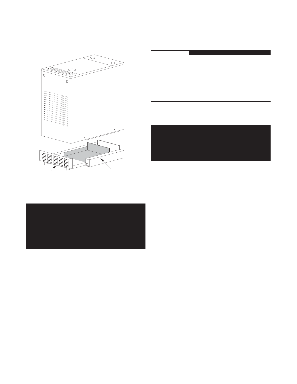
COMBUSTIBLE FLOOR OPTION
The GV100W boiler has been designed for use on noncombustible floors only. If a GV100W boiler is to be installed
on combustible flooring of any type, it MUST be installed using
the special base designed by the Smith Cast Iron Boiler Co.
Never use a substitute base when installing this boiler on
a combustible floor!
WARNING: Never install a GV100W boiler on
combustible flooring without using the special base
specifically designed for it by the Smith Cast Iron Boiler
Co. Do not alter in any way, the special base supplied
by the Smith Cast Iron Boiler Co. Failure to comply with
this warning may result in a fire causing extensive
property damage, severe personal injury or death!
To order the special base contact the nearest Smith Cast Iron
Boiler distributor and ask for Smith’s Special Base, Part No.
CB100-(sections). The number of sections is part of the model
number recorded on the rating plate. If the model number is
GV100W-7, the “-7” specifies that the boiler has seven sections.
Therefore, the proper special base would be Part No.
CB100-7. If the model number has a -3 order special base Part
No. CB100-3, etc.
If the GV100W is being installed in an alcove or closet ensure
that the distances between the boiler and all combustible
construction are greater than or equal to the minimum
distances listed in FIG. NO. 1.
CAUTION: Take care not to damage the burners, pilot or
any other gas train components during this procedure. If
a component is damaged, it must be replaced!
Determine the best boiler location by following the instructions
in the BOILER LOCATION section of this manual. Remove the
front access panel and position the boiler in front of this location
leaving room behind the boiler to work. Tightly thread a 1 1/4"
elbow onto the close nipple in the supply pipe so the opening
faces the front of the boiler. Thread a 4' length of 11/4" pipe
into the elbow and carefully lift the front of the boiler. Slide a
3" thick brick or block under the first 1" of each boiler base
side panel. Make sure the boiler is steady and won’t shift to
the side. Remove the 4' length of pipe. Rotate the 1 1/4" elbow
so it’s opening faces the back of the boiler. Thread the 4' length
of pipe, or a shorter one if necessary, back into the elbow.
Place the special base behind the boiler. Using extreme care
lift the boiler up and slide the special base under the boiler.
CAUTION: Never lift the boiler by the jacket panels or
damage to the boiler may result!
Make sure that the special base support channels are squarely
under the boiler base side panels. Carfully slide the boiler and
base into position. Center the boiler from side to side and ensure
that the back of the burner base side panels are flush with the
back of the Special Base support channels. Install the front grill
supplied with the Special Base. Complete the boiler installation
in accordance with the instructions set forth in this manual.

GV100W BOILER
INSTALLATION & OPERATING INSTRUCTIONS
FIG. NO. 1 Minimum Clearances to Combustible Construction
Page 5
Clearances A B C D E F
Alcove
in 25 * 6 4 7 4
mm 635 * 152 102 178 102
Closet
in 2526474
mm 635 51 152 102 178 102
To Service
in N/A N/A 6 4 10 10
EF
mm N/A N/A 157 102 254 254
* No front wall for alcoves.
FIG. NO. 2 Boiler Dimensions & Component Locations
18"
8 5/8"
(1)
PRESS.
SWITCH
2 11/16"
6 1/2"
C
A
C
D
B
B
2 11/16"
(1)
INDUCER
(1)
TEMP.
(2)
30"
GAS INLET
(1)
JUNCTION BOX,
CONTROL CENTER
(2)
(2)
13 1/4"
13 1/2"
27 5/8"
SIDE VIEW
11 1/2"
5 5/8"
(2)
6 3/4"
& INDUCER RELAY
(1)
GAS VALVE
A
FRONT VIEW
CONTROL
(1)
Notes: 1. Components located behind front panel
2. Vertical dimensions must be adjusted when using a base pan or concrete foundation under the boiler
TABLE 1 Boiler Dimensions
Boiler Size Dimension Dimension Vent Dia. Vent Dia.
(# Sections) A B CATEGORY I CATEGORY III
Single Wall Galv. Horizontal Vent
in
3 107⁄8
4 135⁄8
5 163⁄8
6 191⁄8
7 217⁄8
mm
276
346
416
486
556
in
27⁄16
313⁄16
53⁄16
69⁄16
715⁄16
mm
62
97
132
167
202
in
mm
4
4
4
5
5
102
102
102
127
127
in
mm
4
4
4
4
4
102
102
102
102
102
FLAME
ROLL-OUT
SWITCH
Page 6
GV100W BOILER
INSTALLATION & OPERATING INSTRUCTIONS
FIG. NO. 3 Special Base Installation
FRONT GRILL
SPECIAL BASE
COMBUSTION AIR
WARNING: This boiler must be supplied with
combustion air in accordance with Section 5.3, Air for
Combustion & Ventilation, of the latest edition of the
National Fuel Gas Code, ANSI Z223.1/NFPA 54 and
all applicable local building codes. Failure to provide
adequate combustion air for this appliance can result
in excessive levels of carbon monoxide which can
result in severe personal injury or death!
TABLE 2 Combustion Air Duct Sizing
Fresh Air 1⁄4" Wire Metal Wooden
Duct Size Mesh Screen Louvers Louvers
3" x 12" 144,000 108,000 36,000
8" x 8" 256,000 192,000 64,000
8" x 12" 384,000 288,000 96,000
1
⁄2" x 16" 512,000 384,000 128,000
8
INPUT BTUH
COMMON VENT SYSTEMS
WARNING: Do not connect this boiler or any other
appliance using a mechanical draft system under
positive pressure to a common vent system! Failure
to comply with this warning could result in the
accumulation of carbon monoxide gas which can
cause severe personal injury or death!
If an existing appliance is removed from a common venting
system, the common venting system may then be too large for
the proper venting of the remaining appliances connected to
it. At the time of removal of an existing boiler, the following steps
shall be followed with each appliance remaining connected to
the common venting system placed in operation, one at a
time, while the other appliances remaining connected to the
common venting system are not in operation.
Au moment du retrait d’une chaudière existante, les mesures
suivantes doivent être prises pour chaque appareil toujours
raccordé au système d’évacuation commun et qui fonctionne
alors que d’autres appareils toujours raccordés au système
d’évacuation ne fonction-nent pas: système d’évacuation.
1. Seal any unused openings in the common vent system.
To operate properly and safely this boiler requires a continuous
supply of air for combustion. Oxygen is used by the burners in
the boiler to burn the gas. An adequate supply of outside air
must be available to replace the air used by this process.
Older houses often have enough “leakage” to provide an
adequate amount of combustion air provided that the demand
for combustion air is not too great. Homes that are relatively
new or “tight” will most likely require the installation of a fresh
air duct or other means of providing air for combustion. Any
home utilizing other gas burning appliances, a fireplace, wood
stove or any type of exhaust fan must be checked for adequate
combustion air when all of these devices are in operation at
one time. Sizing of an outside air duct must be done to meet
the requirements of all such devices, see Table 2.
Sceller toutes les ouvertures non utilisées du sys-tème
d’évacuation.
2. Visually inspect the venting system for proper size and
horizonal pitch and determine that there is no blockage or
restriction, leakage, corrosion and other deficiencies which
could cause an unsafe condition.
Inspecter de façon visuelle le système d’évacu-ation pour
déterminer la grosser et l’inclinaison horizontale qui
conviennent et s’assurer que le système est exempt
d’obstruction, d’étranglement de fruite, de corrosion et autres
défaillances qui pourraient présenter des risques.

GV100W BOILER
INSTALLATION & OPERATING INSTRUCTIONS
Page 7
3. Insofar as is practical, close all building doors and windows
and all doors between the space in which the appliances
remaining connected to the common venting system are
located and other spaces of the building. Turn on cloths dryers
and any appliance not connected to the common venting
system. Turn on any exhaust fans, such as range hoods and
bathroom exhausts, so that they will operate at maximum
speed. Do not operate a summer exhaust fan. Close fireplace
dampers.
Dans la mesure du possible, fermer toutes les portes et les
fenêtres du bâtiment et toutes les portes entre l’espace où les
appareils toujours raccordés du système d’évacuation sont
installés et les autres espaces du bâtiment. Mettre en marche
les sécheuses, tous les appareils non raccordés au système
d’évacuation commun et tous les ventilateurs d’extraction
comme les hottes de cuisinère et les ventilateurs des salles
de bain. S’assurer que ces ventilateurs fonctionnent à la vitesse
maximale. Ne pas faire fonctionner les ventilateurs d’été.
Fermer les registres des cheminées.
4. Place in operation the appliance being inspected. Follow
the lighting instructions. Adjust the thermostat so the appliance
will operate continuously.
Mettre l’appareil inspecté en marche. Suivre les instructions
d’allumage. Régler le thermostat de façon que l’appareil
fonctionne de façon continue.
5. Test for spillage at the draft hood relief opening after 5
minutes of main burner operation. Use the flame of a match or
candle, or smoke from a cigarette, cigar or pipe.
Faire fonctionner le brûleur principal pendant 5 min ensuite,
déterminer si le coupe-tirage déborde à l’ouverture de décharge.
Utiliser la flamme d’une allunette ou d’une chandelle ou la fumée
d’une cigarette, d’un cigare ou d’une pipe.
6. After it has been determined that each appliance
remaining connected to the common venting system properly
vents when tested as outlined above, return doors, windows,
exhaust fans, fireplace dampers and any other gas-burning
appliance to their previous condition of use.
7. Any improper operation of the common venting system
should be corrected so the installation conforms with the
National Fuel Gas Code, ANSI Z223.1/NFPA 54. When resizing
any portion of the common venting system, the common
venting system should be resized to approach the minimum
size as determined using the appropriate tables in Appendix
F in the National Fuel Gas Code, ANSI Z223.1/NFPA 54 and
or CSA B149 Installation Codes.
Tout mauvais fonctionnement du systéme d’évacu-tion commun
devrait étré corrigé de façor que l’installation soit conforme au
National Fue Gas Code, ANSI Z223.1/NFPA 54 et (ou) aux
codes d’in-stallation CSA-B149. Si la grosseur d’une section
du système d’ évacuation doit étré modifiée, le système devrait
étré modifié pour respecter les valeurs minimales des tableaux
pertinents de l’appendice F du National Fuel Gas Code, ANSI
Z223.1/ NFPA 54 et (ou) des codes d’installation CSA-B149.
CHIMNEY VENTING
WARNING: This boiler must be vented in accordance
with Part 7, Venting of Equipment, of the latest edition
of the National Fuel Gas code, ANSI Z223.1/NFPA 54
and all applicable local building codes. In Canada,
follow CAN/CGA B149.1 or .2 Installation Codes.
Improper venting of this appliance can result in
excessive levels of carbon monoxide which can result
in severe personal injury or death!
Chimney Inspection & Sizing
A GV100W series boiler can be vented into a masonry
chimney, FIG. NO. 4, provided several conditions are met:
• a thorough inspection of the chimney must be performed.
• the chimney must have a vitreous tile lining that is clean,
properly constructed and properly sized.
• the chimney must not be located on an external wall or be
located in an unheated space unless the chimney is lined with
a corrosion resistant metal liner and a condensate trap is
installed.
Une fois qu’il a été d éterminé, selon la métode indiquée cidessus, que chaque appareil raccordé au système
d’évacuation est mis à l’air libre de façor adéquate. Remettre
les portes et les fenêtres, les ventilateurs, les registres de
cheminées et les appareils au gaz à leur position originale.
• the boiler must not be connected to a flue used for a
fireplace, wood stove or other solid fuel device.
If possible the boiler and a gas fired hot water heater should
be connected to the same chimney flue. They must have their
own vent connector and enter the flue at least 6 in,
apart. Consult the latest revision of the National Fuel Gas Code,
ANSI Z223.1 and follow all local codes to ensure that the
chimney is the proper size for the given installation.
WARNING: Failure to connect this boiler to the
chimney using vent pipe of the proper diameter, as
listed in Table 1, could cause carbon monoxide
poisoning leading to death!
152 mm
Page 8
GV100W BOILER
INSTALLATION & OPERATING INSTRUCTIONS
Vent Connections to Chimneys
Use Type B1 or single wall metal vent pipe from the boiler to
the chimney. If used, a 4 in to 5 in,
increaser must be fastened directly to the boiler vent collar with
sheet metal screws no longer than 1/2 in,
shortest, straightest vent system possible for the particular
application. The vent system should be sloped up toward the
2 cm/m
chimney 1/4 in/ft,
supported and each connection securely fastened with at least
3 corrosion resistant sheet metal screws. The termination of
the vent pipe must be flush with the inside of the chimney flue.
Always provide a minimum clearance of 6 in,
single wall metal vent pipe and any combustible materials. Type
B1 vent may be used, clearance between it and any
combustible material must be as listed.
WARNING: Failure to maintain minimum clearances
between vent connectors and combustible materials
can result in a fire causing extensive property damage,
severe personal injury or death!
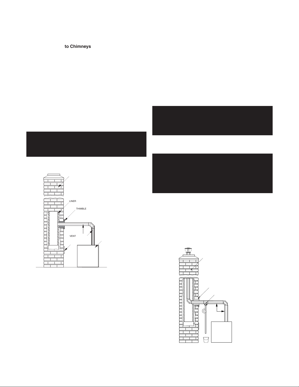
FIG NO. 4 Chimney Venting
. Ensure that the flue pipe is properly
CHIMNEY
102 mm to 127 mm
13 mm
. Use the
152 mm
, between
Single Wall Metal Vent
GV100W boilers may be vented vertically using single wall
metal vent pipe sized per Table 1. Galvanized sheet metal pipe
must have a minimum wall thickness of 26 gauge. In Canada,
pipe constructed of .025 in,
inch thick stainless steel may be required.
The use of thimbles, firestops and other protective devices
when penetrating combustible or noncombustible construction
must be in accordance with all applicable national and local
codes.
WARNING: Single wall vent pipe must NEVER pass
through interior walls or through floors or ceilings!
Failure to comply with this warning could result in a
fire causing extensive property damage, severe
personal injury or death!
An unused chimney flue can be used as a raceway for single
wall metal pipe, see FIG. NO. 4A.
WARNING: Never run vent pipe through a chimney flue
that has another appliance attached to it! Never
connect another appliance to a pressurized vent
system, it must serve only one appliance. Failure to
comply with this warning can result in excessive
levels of carbon monoxide causing severe personal
injury or death!
0.63 mm
, thick aluminum or .018
LINER
THIMBLE
VENT SYSTEM
CLEANOUT
BOILER
VERTICAL VENTING
B Vent
The boiler may be vented vertically using the proper size Type
B1 vent pipe. Do not use the boiler as a load bearing element.
The vent system must be fully supported by the building
structure. Use an approved vent terminal at the vent outlet
which must extend at least 3 ft,
where it passes through the roof. In addition, the vent pipe must
be at least 2 ft,
within a horizontal distance of 10 ft,
0.6 m
higher than any portion of the building
1 m
, above the highest point
3 m
.
A listed vent terminal designed for the type of pipe being used
must complete the vertical run where it exits the chimney. If
the chimney is on an outside wall or in an unheated space the
optional condensate tee and trap pictured in FIG. NO. 4A may
be required. The trap is made by ty-rapping a loop in the 3/8"
clear plastic tubing attached to the tee and filling it with water.
Do not operate the boiler without this trap!
FIG. NO 4A Vertical Venting Through a Chimney
CHIMNEY
THIMBLE
CONDENSATE
DRAIN ASS'Y.
WARNING
S
VENT
SYSTEM
BOILER
 Loading...