

Smith Cast Iron Boilers GB300 User Manual
GB300-IOM-4
GB300
NATURAL OR PROPANE GAS BOILER
INSTALLATION & OPERATING MANUAL
Designed and tested according to A.S.M.E. Boiler and Pressure Vessel Code, Section
IV for a maximum allowable working pressure of 80 psi US, 50 psi Canada water,
15 psi steam.
CAUTION: Do not use automotive anti-freeze in the boiler waterways. If the use of
antifreeze is necessary an anti-freeze specifically formulated for hydronic heating
systems must be used!
Water treatment is not recommended. This boiler uses gaskets made from ethylene
propylene, EPT, to seal the section ports. Consult a water treatment professional before
adding any chemicals to the boiler water to ensure that they are compatible with the
gaskets. Failure to comply with this caution can result in failure of the gaskets voiding
the warranty.
WARNING: If the information in this manual is not followed exactly, a fire or explosion
may result causing property damage, personal injury or loss of life.
Do not store or use gasoline or other flammable vapors and liquids in the vicinity of
this or any other appliance.
WHAT TO DO IF YOU SMELL GAS:
• Do not try to light any appliance.
• Do not touch any electrical switch. Do not use any phone in your building.
• Immediately call your gas supplier from a neighbor's phone. Follow the gas supplier's
instructions.
• If you cannot reach your gas supplier, call the fire department.
A qualified installer, service agency or the gas supplier, must perform installation
and service.
INSTALLER READ THESE INSTRUCTIONS CAREFULLY.
THEY WILL SAVE YOU VALUABLE TIME WHEN ASSEMBLING THE BOILER.
THESE INSTRUCTIONS TO BE AFFIXED ADJACENT TO THE BOILER.
CONSUMER, RETAIN THESE INSTRUCTIONS FOR FUTURE REFERENCE PURPOSES.
WESTCAST, INC.
260 NORTH ELM STREET WESTFIELD, MA 01085
TEL. (413) 562-9631 FAX (413) 562-3799
www.smithboiler.com

Page 2
GB300 BOILER INSTALLATION AND OPERATION INSTRUCTIONS
Assurez-vous de bien suivre les instructions données dans cette
notice pour réduire au minimum le risque d'incendie ou d'explosion ou pour éviter
tout dommoge matériel, toute blessure ou la mort
Ne pas entreposer ni utiliser d'essence ou ni d'autres vapeurs ou liquides inflammables
à proximité de cet appareil ou de tout autre appareil.
QUE FAIRE SI VOUS SENTEZ UNE ODEUR DE GAZ:
• Ne pas tenter d'allumer d'appareil.
• Ne touchez à aucun interrupteur; ne pas vous servir des téléphones se trouvant dans
le bâtiment.
• Appelez immédiatement votre fournisseur de gas depuis un voisin. Suivez les
intructions du fournisseur.
• Si vous ne purvez rejoindre le fournisseur, appelez le service des incendies.
L'installation et l'entretien doivent être assurés par un installateur ou un service
d'entretien qualifié ou par le fournisseur de gaz.
CONTENTS
Getting Started ...................................................page 2
Boiler Ratings & Capacities................................page 3
Boiler Location ................................................... page 3
Combustion Air & Ventilation .............................. page 4
Chimney & Vent Pipe Connections .................... page 5
Boiler Assembly .............................................. page 11
Heating System Piping ..................................... page 35
Gas Supply Piping............................................page 39
Electrical Wiring ............................................... page 40
Boiler Operation .............................................. page 41
Lighting Instructions ......................................... page 42
Boiler Checking & Adjustment..........................page 43
Boiler Maintenance .......................................... page 44
Repair Parts .....................................................page 46
Health Warnings .......................................... back cover
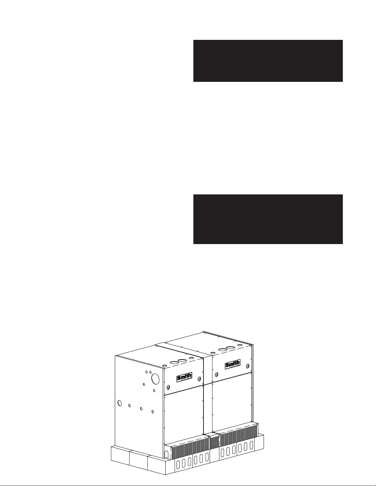
BEFORE YOU START
This manual covers the application, installation, operation
and maintenance of a GB300(S,W) low pressure steam
or hot water boiler.
To obtain the safe, dependable, efficient operation and
long life for which this boiler was designed, these
instructions must be read, understood and followed.
The GB300(S,W) boilers have been design certified by
CSA for use with natural and propane gas under the
latest revision of ANSI-Z21.13/CSA 4.9 Gas-Fired Low
Pressure Steam and Hot Water Boilers and CGA 3.3,
Gas-Fired Steam and Hot Water Boilers. Each unit has
been constructed and hydrostatically tested for a
maximum working pressure of 80 psi US, 50 psi
Canada, 15 psi steam in accordance with Section IV of
the A.S.M.E. Boiler and Pressure Vessel Code for cast
iron boilers.
All aspects of the boiler installation must conform to the
requirements of the authority having jurisdiction, or, in
the absence of such requirements, to the National Fuel
Gas Code, ANSI Z223.1/NFPA - latest revision. Where
required by the authority having jurisdiction, the
installation must conform to the Standard for Controls
and Safety Devices for Automatically Fired Boilers,
ANSI/ASME CSD-1.
This product must be installed by a licensed plumber or
gas fitter when installed within the Commonwealth of
Massachusetts.
In Canada, the installation must be in accordance with
the requirements of CAN/CGA B149.1 or .2, Installation
Code for Gas Burning Appliances and Equipment.
The owner should maintain a record of all service work
performed with the date and a description of the work
done. Include the name of the service organization for
future reference.
Direct all questions to your Smith Cast Iron Boiler
distributor or contact the Smith Customer Service
Department, 260 North Elm Street, Westfield, MA 01085.
Always include the model and serial numbers from the
rating plate of the boiler in question.
GB300 BOILER INSTALLATION AND OPERATION INSTRUCTIONS
Page 3
BOILER RATINGS & CAPACITIES
Before undertaking the installation of the GB300(S,W)
boiler check the boiler rating plate to ensure that the boiler
has been sized properly for the job. The rating label has
been packed with the controls. The “Net I=B=R Ratings”
specify the equivalent amount of direct cast iron radiation
that the boiler can supply under normal conditions. Also
ensure that the boiler has been set up for the type of gas
available at the installation site. Other important
considerations are the availability of an adequate
electrical supply, fresh air for combustion and a suitable
chimney or vent system.
BOILER LOCATION
1. Locate the boiler in an area that provides good
access to the unit. Servicing may require the removal of
jacket panels. Allow a minimum clearance of 2 ft,
between adjacent construction and the boiler sides and
draft hood. A minimum clearance of 4 ft,
maintained between the front of the boiler and adjacent
construction. Accessibility clearances should take
precedence over fire protection clearances, or use which
ever is greater.
2. An optimum site will be level, central to the piping
system, close to a chimney and have adequate fresh air
for combustion.
1.22 m
0.61 m
must be
WARNING: Never install a GB300(S,W) boiler on
top of combustible flooring! Failure to comply
with this warning may result in a fire causing
extensive property damage, severe personal
injury or death!
4. DO NOT install this boiler in a location that would
subject any of the gas ignition components to direct
contact with water or excessive moisture during operation
or servicing. A full concrete foundation is recommended
to protect the boiler from moisture and debris, Figure 1.
NOTE: The boiler must be assembled on a level, noncombustible surface. If the floor is not level a pad
must be poured to provide a level surface. If a
concrete block base is used level it using noncombustible shims or grout.
5. DO NOT place this boiler in a location that would
restrict the introduction of combustion air into the boiler.
WARNING: Never store combustible materials,
gasoline or any product containing flammable
vapors or liquids in the vicinity of the boiler.
Failure to comply with this warning can result in
an explosion or fire causing extensive property
damage, severe personal injury or death!
3. Ensure that the floor is structurally sound and will
support the weight of the boiler. Never install a
GB300(S,W) on a concrete floor that contains wires,
cables, water pipes or hoses. This boiler is designed for
non combustible floors only! Never install this boiler on
combustible materials or carpeting even if a noncombustible foundation material is placed over them!
Figure 1 Concrete Block Base Construction

Page 4
GB300 BOILER INSTALLATION AND OPERATION INSTRUCTIONS
COMBUSTION AIR & VENTILATION
WARNING: This boiler must be supplied with
combustion air in accordance with Section 5.3,
Air for Combustion & Ventilation, of the latest
revision of the National Fuel Gas Code, ANSI
Z223.1/NFPA 54 and all applicable local building
codes. Canadian installations must comply with
CAN/CGA B149.1 or .2 Installation Code. Failure
to provide adequate combustion air for this boiler
can result in excessive levels of carbon
monoxide which can result in severe personal
injury or death!
WARNING: Never operate a GB300 in an
environment subjected to a negative pressure
unless it is Direct Vented. Failure to comply with
this warning can result in excessive levels of
carbon monoxide causing severe personal injury
or death!
To operate properly and safely this boiler requires a
continuous supply of air for combustion. Oxygen is used
by the boiler burners to burn the gas. NEVER store
objects on or around the boiler. In addition, air is also
used to assist in the safe disposal of the products of
combustion. This air is known as dilution air and mixes
with the products of combustion to assist in their exit
through the flue pipe and chimney. An adequate supply
of air must be available to replace the air used by these
processes.
Older buildings often have enough natural infiltration to
provide an adequate amount of combustion air provided
that the demand for combustion air is not too great.
Buildings that are relatively new or “tight” will most likely
require the installation of a fresh air duct or other means
of providing make-up air. Any building utilizing other gas
burning appliances, a fireplace, wood stove or any type
of exhaust fan must be checked for adequate combustion
air when all of these devices are in operation at one time.
Sizing of an outside air duct must be done to meet the
requirements of all such devices.
All Air From Inside The Building
If the boiler is to be located in a confined space
minimum clearances of 2 ft,
between the boiler and any adjacent construction. When
installed in a confined space two permanent openings
communicating with an additional room(s) are required.
The combined volume of these spaces must have
sufficient volume to meet the criteria for an unconfined
space. The total air requirements of all gas utilization
equipment, fireplaces, wood stoves or any type of
exhaust fan must be considered when making this
determination.
0.61 m
must be maintained
Each opening must have a minimum free area of
2
1 in
/1000 Btu/hr,
2200 mm2/kW
based on the total
input rating of ALL gas utilization equipment in the
confined area. Each opening must be no less than
100 in2,
64,516 mm
within 12 in,
2
300 mm
in size. The upper opening must be
of, but not less than 3 in,
80 mm
from, the top of the enclosure. The bottom opening must
be within 12 in,
300 mm
of, but not less than 3 in,
80 mm
from, the bottom of the enclosure.
All Air From Outside The Building
When installed in a confined space two permanent
openings communicating directly with, or by ducts to,
the outdoors or spaces that freely communicate with the
outdoors must be present. The upper opening must be
within 12 in,
300 mm
of, but not less than 3 in,
80 mm
from, the top of the enclosure. The bottom opening must
be within 12 in,
300 mm
of, but not less than 3 in,
80 mm
from, the bottom of the enclosure.
Where directly communicating with the outdoors
or communicating with the outdoors through vertical
ducts, each opening shall have a minimum free area
of 1 in2/4000 Btu/hr,
550 mm2/kW
of the total input
rating of all of the equipment in the enclosure.
Where communicating with the outdoors through
horizontal ducts, each opening shall have a minimum
free area of 1 in2/2000 Btu/hr,
1100 mm2/kW
of the
total input rating of all of the equipment in the enclosure.
When ducts are used, they must have the same crosssectional area as the free area of the opening to which
they connect.
When calculating the free area necessary to meet the
make-up air requirements of the enclosure, consideration
must be given to the blockage effects of louvers, grills
and screens. Screens must have a minimum mesh size
of 1/4 in,
6.4 mm
. If the free area through a louver or grill
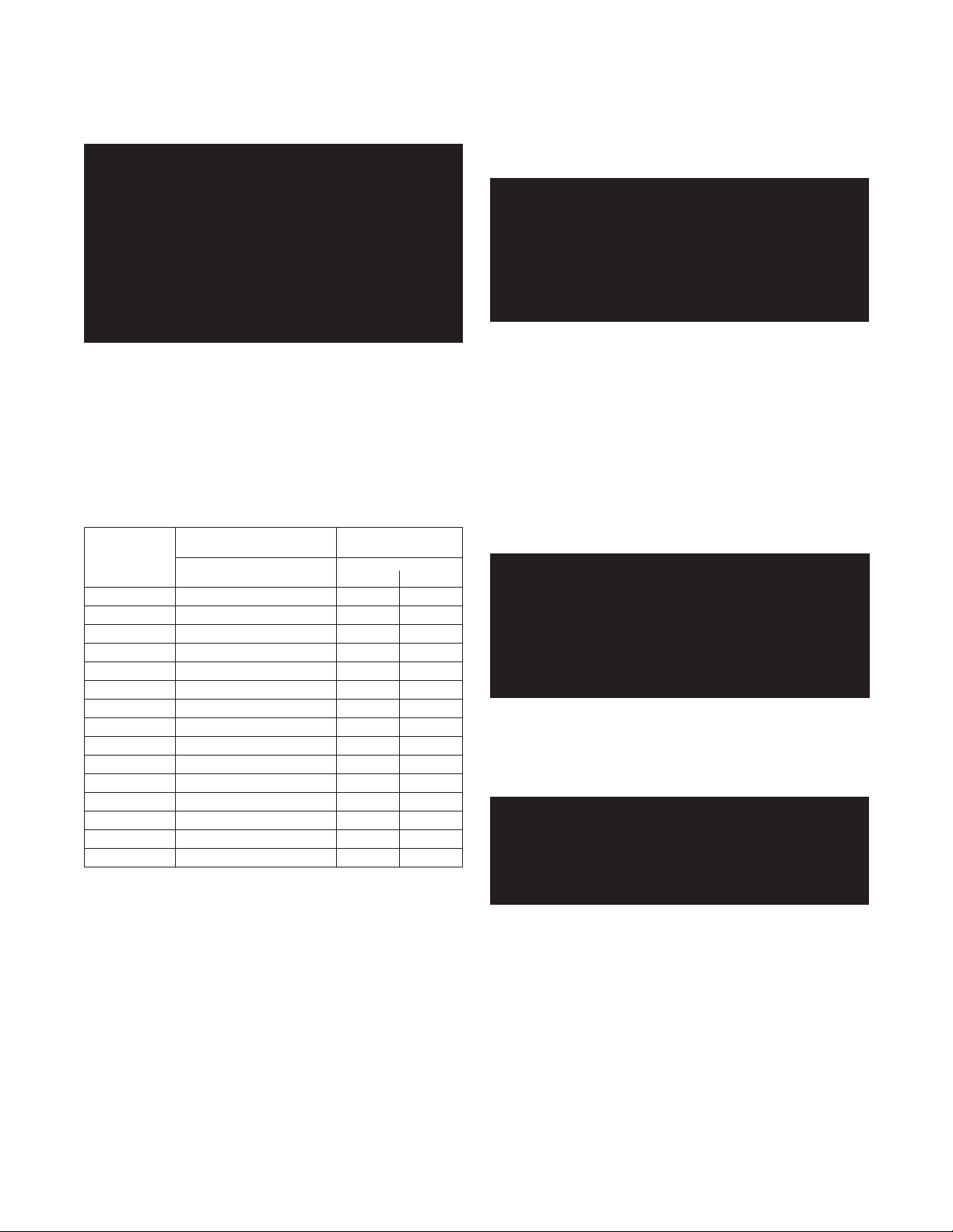
is not known ducts should be sized per Table 1 below.
Table 1 Make-up Air Duct Sizing
Required Cross Sectional Duct Area
Input 1/4 in,
6.4 mm
Metal Wooden
(MBH) Wire Screen Louvers Louvers
2
in
400 100
600 150
800 200
1000 250
1200 300
1400 350
1600 400
1800 450
2000
500 3226
cm
645
968
1290
1613
1935
2258
2581
2903
2
2
in
133
200
267
333
400
467
533
600
667
cm
858
1290
1723
2148
2581
3013
3439
3871
4303
2
2
in
400
600
800
1000
1200
1400
1600
1800
2000
10,323
11,613
12,904
2
cm
2581
3871
5161
6452
7742
9032
GB300 BOILER INSTALLATION AND OPERATION INSTRUCTIONS
Page 5
CHIMNEY & VENT PIPE CONNECTIONS
WARNING: The vent installation must be in
accordance with Part 7, Venting of Equipment, of
the National Fuel Gas Code, ANSI Z223.1/NFPA54latest revision or applicable provisions of the
local building codes. Canadian installa-tions
must comply with CAN /CGA B149.1 or .2
Installation Code. Improper venting of this boiler
can result in excessive levels of carbon
monoxide, which can result in severe personal
injury or death!
Chimney Inspection & Sizing
If this boiler will be connected to a masonry chimney, a
thorough inspection of the chimney must be performed.
Ensure that the chimney is clean, properly constructed
and properly sized. Table 2 lists the equivalent breeching
and flue sizes required for the GB300 boilers.
Table 2 Vent Outlet, Equivalent Breeching
& Chimney Size
Vent Outlets
Boiler Diameter
Model
GB300-5 1@10 10
GB300-6 1@12 12
GB300-7 1@12 12
GB300-8 2@10 14
GB300-9 2@10 14
GB300-10 2@10 14
GB300-11 2@12 15
GB300-12 2@12 15
GB300-13 2@12 15
GB300-14 1@12, 2@10 16
GB300-15 4@10 17
GB300-16 4@10 17
GB300-17 4@10 17
GB300-18 4@10 17
GB300-19 4@10 17
NOTE: These sizes are based on a 20 foot chimney height.
# of outlets/dia. in inches
Equivalent Breeching
& Chimney size
inches
mm
254
305
305
356
356
356
381
381
381
406
432
432
432
432
432
When more than one appliance is connected to the same
chimney flue the flue must be large enough to safely
vent the combined output of all the appliances.
WARNING: If an appliance using any type of a
mechanical draft system operating under
positive pressure is connected to a chimney flue,
never connect any other appliances to this flue.
Doing so can result in the accumulation of
carbon monoxide which can cause severe
personal injury or death!
VENT CONNECTIONS
Always use a type B or single wall galvanized metal vent
pipe the same diameter as the draft hood flue collar. Use
the shortest, straightest vent system possible for the
installation. If horizontal runs exceed 6 feet they must
be supported at maximum 6 foot intervals with overhead
hangers. The vent system should be sloped up towards
the chimney at a minimum rate of 1/4 inch/foot and
terminate flush with the inside of the chimney flue.
Fasten each connection with at least 3 corrosion
resistant sheet metal screws.
WARNING: Never modify or alter any part of the
boiler’s draft hood. This includes the removal or
alteration of any baffles. Never install a vent pipe
of a diameter different than that of the boiler
draft hood flue collar. Failure to comply with this
warning can result in severe personal injury or
death.
Always provide a minimum clearance of 6 inches between
type C vent pipe and any combustible materials. Type
B1 vent may be used, clearance between it and any
combustible material must be as listed.
WARNING: Failure to maintain minimum
clearances between vent connectors and any
combustible material can result in a fire causing
extensive property damage, severe personal
injury or death!

Page 6
GB300 BOILER INSTALLATION AND OPERATION INSTRUCTIONS
COMMON VENT SYSTEMS
If an existing boiler is removed from a common venting
system, the common venting system may then be too
large for the proper venting of the remaining appliances
connected to it. At the time of removal of an existing
boiler, the following steps shall be followed with each
appliance remaining connected to the common venting
system placed in operation, while the other appliances
remaining connected to the common venting system are
not in operation.
Au moment du retrait d'une chaudière existante, les
mesures suivantes doivent être prises pour chaque
appareil toujours raccordé au système d'évacuation
commun et qui fonctionne alors que d'autres appareils
toujours raccordés au système d'évacuation ne fonctionnent pas: système d'évacuation.
a. Seal any unused openings in the common venting
system.
Sceller toutes les ouvertures non utilisées du
système d'évacuation.
b. Visually inspect the venting system for proper size
and horizontal pitch and determine there is no
blockage or restriction, leakage, corrosion and other
deficiencies which could cause an unsafe condition.
Inspecter de façon visuelle le système d'évacu-ation
pour déterminer la grosser et l'inclinaison horizontale
qui conviennent et s'assurer que le système est
exempt d'obstruction, d'étranglement de fruite, de
corrosion et autres défaillances qui pourraient
présenter des risques.
c. Where it is practical, close all building doors and
windows and all doors between the space in which
the appliances remaining connected to the common
venting system are located and other spaces of the
building. Turn on clothes dryers and any appliance
not connected to the common venting system.
Turn on any exhaust fans, such as range hoods and
bathroom exhaust, so they will operate at maximum
speed. Do not operate a summer exhaust fan. Close
fireplace dampers.
Dans la mesure du possible, fermer toutes les portes
et les fenêtres du bâtiment et toutes les portes entre
l'espace où les appareils toujours raccordés du
système d'évacuation sont installés et les autres
espaces du bâtiment. Mettre en marche les
sécheuses, tous les appareils non raccordés au
système d'évacuation commun et tous les
ventilateurs d'extraction comme les hottes de
cuisinère et les ventilateurs des salles de bain.
S'assurer que ces ventilateurs fonctionnent à la
vitesse maximale. Ne pas faire fonctionner les
ventilateurs d'été. Fermer les registres des
cheminées.
d. Place in operation the appliance being inspected.
Follow the lighting instructions. Adjust thermostat so
appliance will operate continuously.
Mettre l'appareil inspecté en marche. Suivre les
instructions d'allumage. Régler le thermostat de
façon que l'appareil fonctionne de façon continue.
GB300 BOILER INSTALLATION AND OPERATION INSTRUCTIONS
Page 7
e. Test for spillage at the draft hood relief opening after
5 minutes of main burner operation. Use the flame
of a match or candle, or smoke from a cigarette, cigar
or pipe.
Faire fonctionner le brûleur principal pendant 5 min
ensuite, déterminer si le coupe-tirage déborde à
l'ouverture de décharge. Utiliser la flamme d'une
allunette ou d'une chandelle ou la fumée d'une
cigarette, d'un cigare ou d'une pipe.
f. After it has been determined that each appliance
remaining connected to the common venting system
properly vents when tested as outlined above, return
doors, windows, exhaust fans, fireplace dampers and
any other gas-burning appliance to their previous
condition of use.
Une fois qu'il a été d éterminé, selon la métode
indiquée ci-dessus, que chaque appareil raccordé
au système d'évacuation est mis à l'air libre de façor
adéquate. Remettre les portes et les fenêtres, les
ventilateurs, les registres de cheminées et les
appareils au gaz à leur position originale.
g. Any improper operation of the common venting
system should be corrected so the installation
conforms with the National Fuel Gas Code, ANSI
Z223.1/NFPA 54. When resizing any portion of the
common venting system, the common venting
system should be resized to approach the minimum
size as determined using the appropriate tables in
Part 11 in the National Fuel Gas Code, ANSI Z223.1/
NFPA 54.
Tout mauvais fonctionnement du systéme d'évacution commun devrait étré corrigé de façor que l'installation soit conforme au National Fuel Gas Code,
ANSI
Z223.1/NFPA 54 et (ou) aux codes d'installation
CSA-B149. Si la grosseur d'une section du système
d' évacuation doit étré modifiée, le système devrait
étré modifié pour respecter les valeurs minimales
des tableaux pertinents de l'appendice F du National
Fuel Gas Code, ANSI Z223.1/NFPA 54 et (ou) des
codes d'installation CSA-B149.
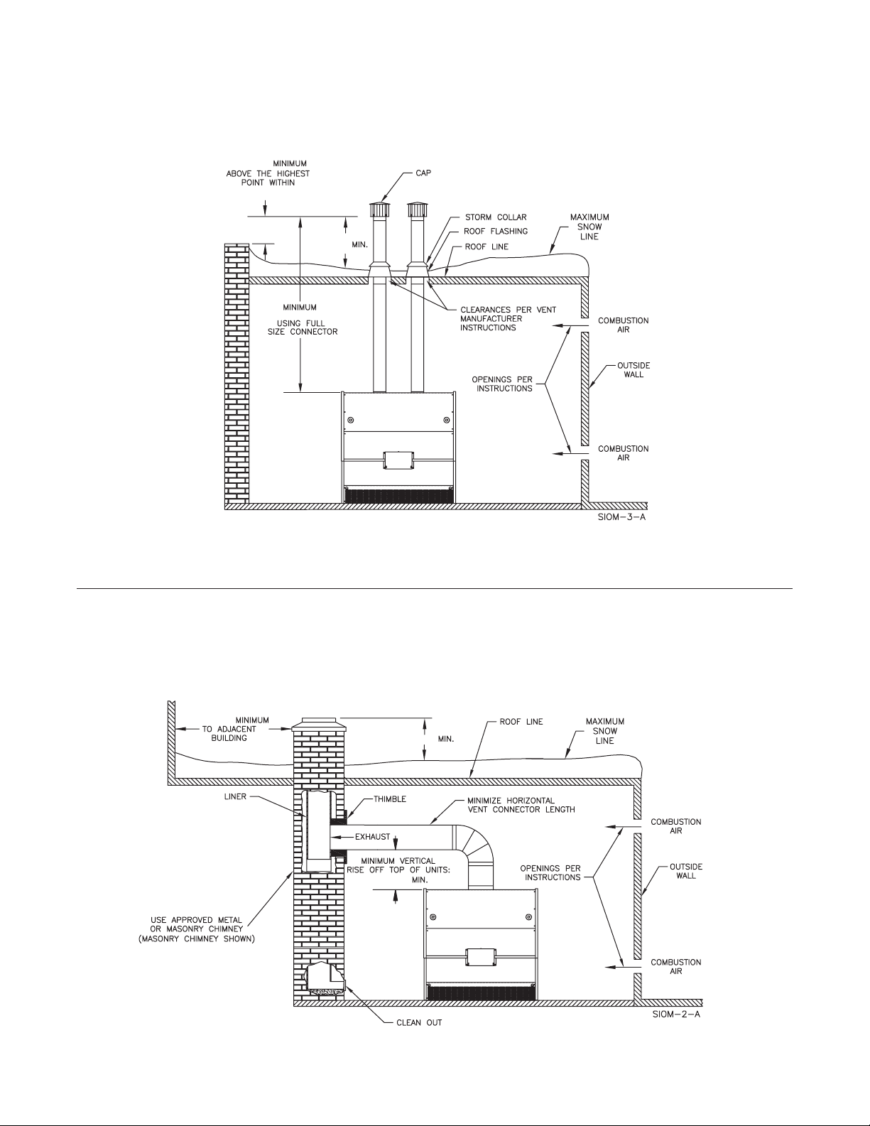
Figure 2A Vertical Venting Using A Metal Chimney System And Inside Air(GB300 Series)
2 FT 0.6 m
10 FT 3.4 m
3 FT 0.9 m
3 FT 0.9 m
Page 8
GB300 BOILER INSTALLATION AND OPERATION INSTRUCTIONS
Figure 2B Dual Flue Outlets And Inside Air (GB300 Series)
2 FT 0.6 m
10 FT 3.4 m
3 FT 0.9 m
5 FT 4.5 m
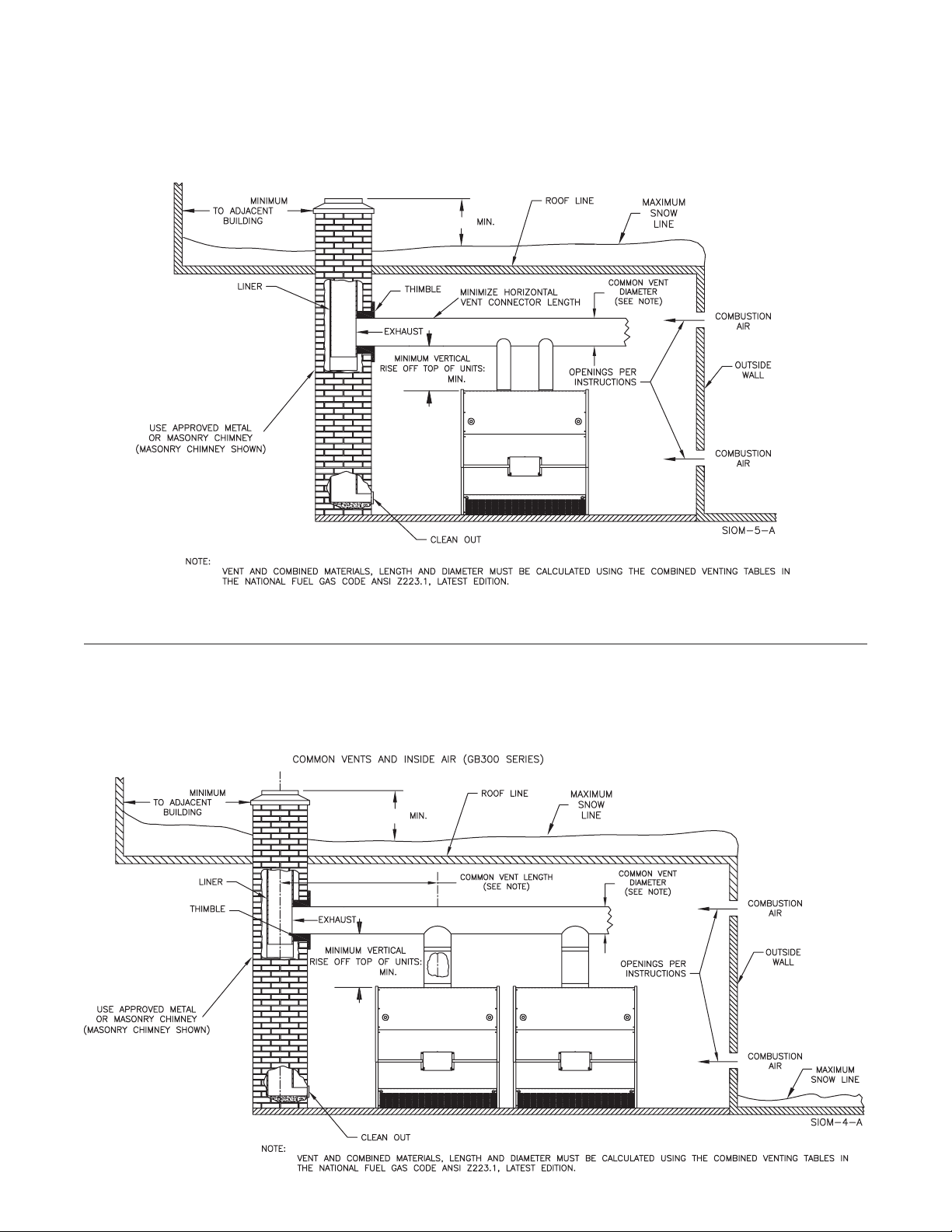
Figure 2C Vertical Venting Using A Masonry Chimney And Inside Air (GB300 Series)
10 FT 3.1 m
3 FT 0.9 m
3 FT 0.9 m
GB300 BOILER INSTALLATION AND OPERATION INSTRUCTIONS
Figure 2D Dual Flue Outlets Using A Masonry Chimney And Inside Air (GB300 Series)
10 FT 3.1 m
3 FT 0.9 m
3 FT 0.9 m
Page 9
Figure 2E Common Vents And Inside Air (GB300 Series)
10 FT 3.1 m
3 FT 0.9 m
3 FT 0.9 m
Page 10
GB300 BOILER INSTALLATION AND OPERATION INSTRUCTIONS
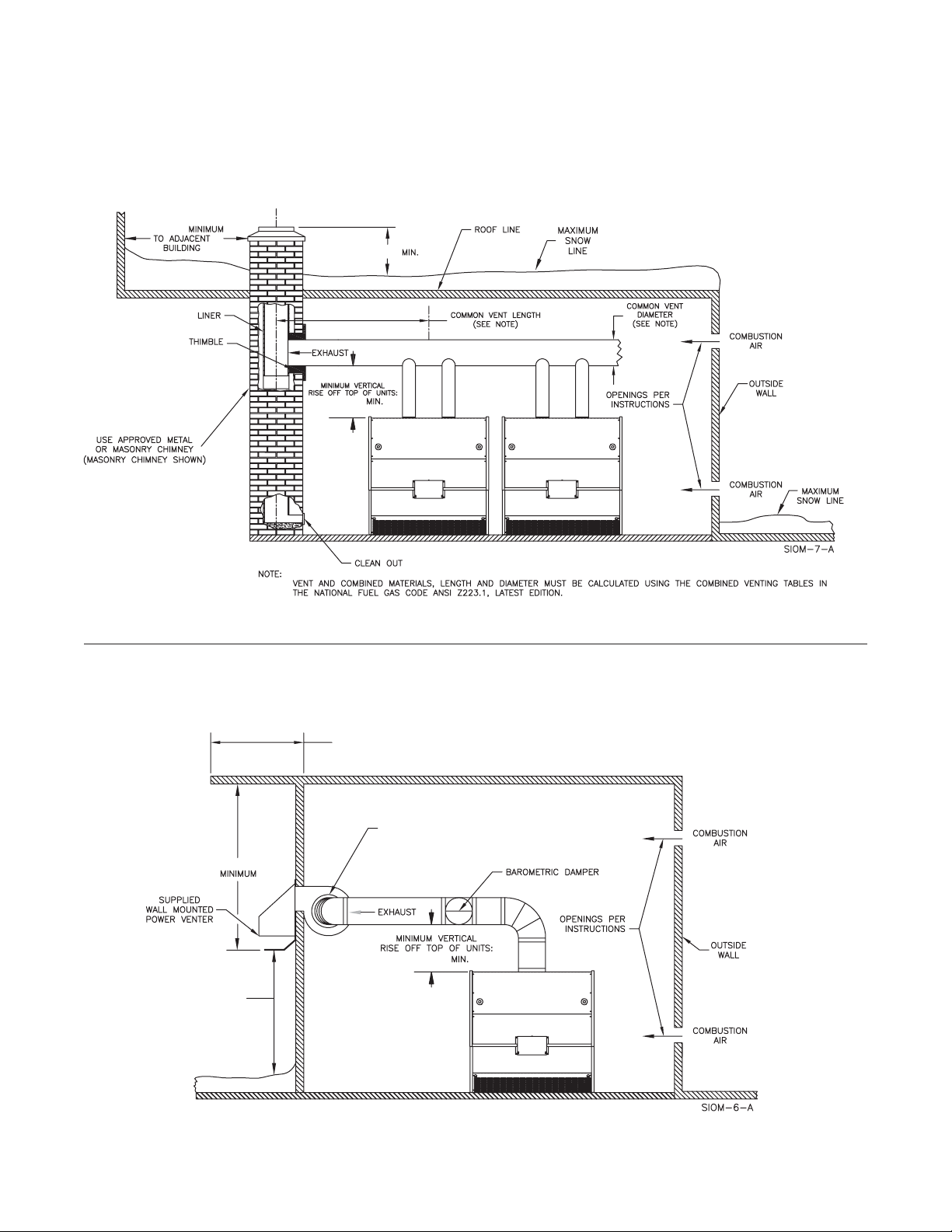
Figure 2F Dual Flue Outlets With Two Boilers Using A Masonry Chimney And Inside Air (GB300 Series)
10 FT 3.1 m
3 FT 0.9 m
3 FT 0.9 m
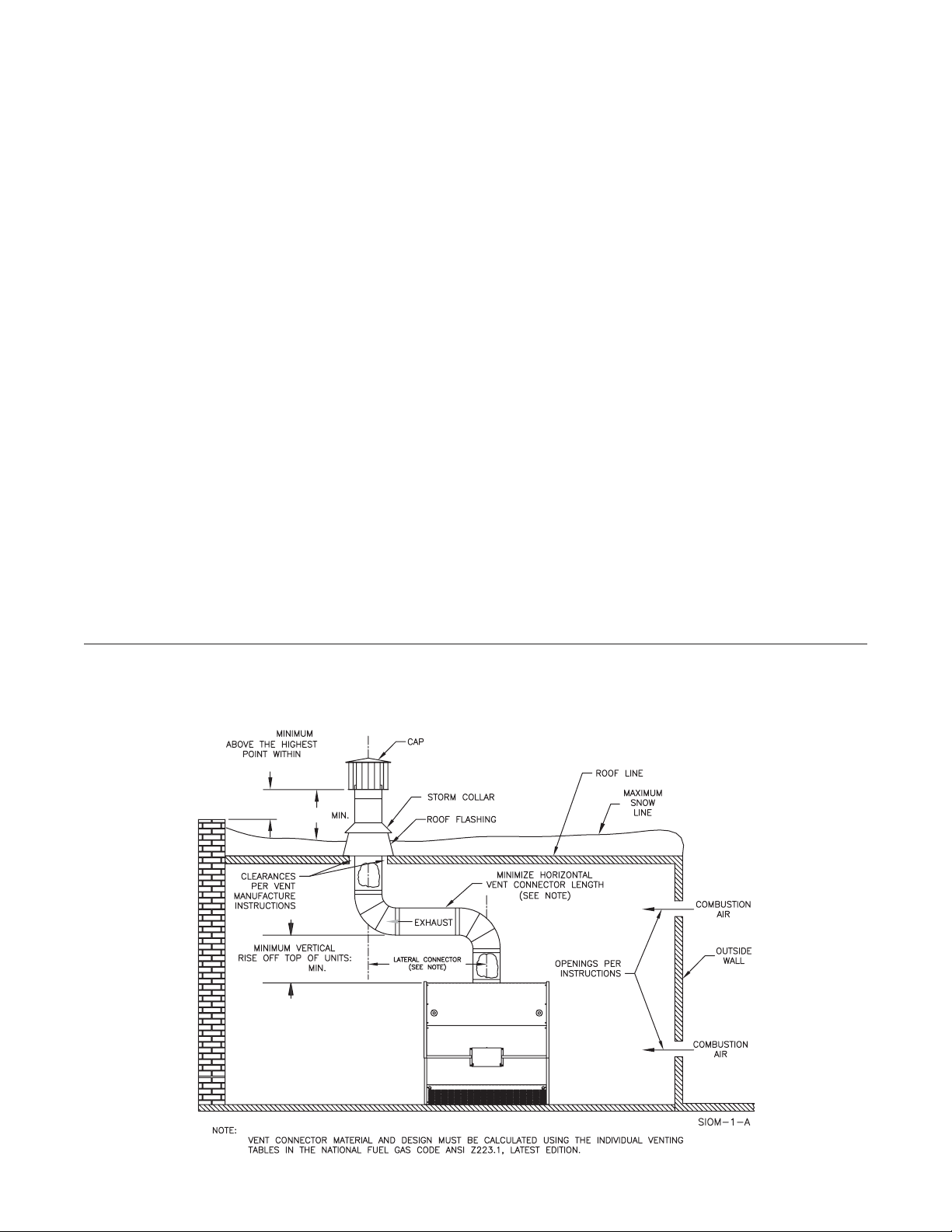
Figure 2G Horizontal Venting And Inside Air (GB300)
BUILDING OVERHANG
4 FT 1.2 M MAX.
PITCH PIPE DOWN TOWARDS TERMINAL
CAP 1/4 IN. PER FOOT 20MM/M OF RUN TO
ALLOW FOR CONDENSATE DRAINAGE
3 FT 0.9 m
3 FT 0.9 m
1.5 FT 0.5m MINIMUM
DISTANCE FROM
EXHAUST TO MAXIMUM
SNOW LINE.
GB300 BOILER INSTALLATION AND OPERATION INSTRUCTIONS
Page 11
BOILER ASSEMBLY
Locate the boiler installation site based on the guidelines
set forth in the previous pages. A full concrete block
foundation is recommended to protect the boiler from
moisture and debris. Use solid blocks to support the boiler
and hollow blocks for the rest, Figure 1. Align the hollow
blocks so air can flow through them.
WARNING: Never install a GB300(S,W) boiler on
top of combustible flooring! Failure to comply
with this warning may result in a fire causing
property damage, severe personal injury or
death!
Burner Base Assembly General Instructions
WARNING: The burner base must be assembled
as outlined below. Do not make substitutions for
the hardware or materials supplied for the burner
base assemblies. Failure to comply with this
warning may result in property damage, severe
personal injury or death!
Check the contents of the burner base cartons against
the enclosed packing list to ensure that all of the required
parts are present. If they are not, contact your Smith Cast
Iron Boiler distributor or contact the Smith Customer
Service Department.
The burner base panels are factory insulated to simplify
field assembly of the burner base.
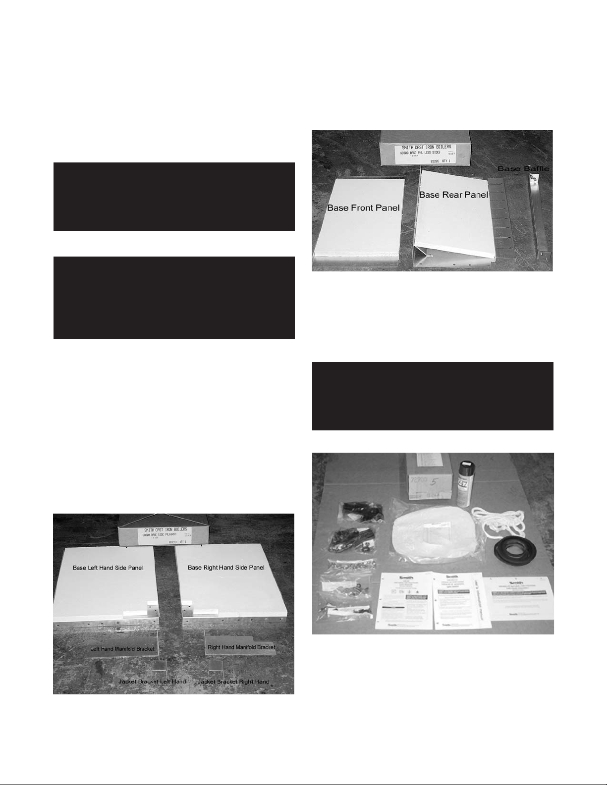
Box 63273, Burner Base Side Panels & Brackets,
contains the left & right burner base side panels, manifold
brackets and the jacket brackets, Figure 3.
A box with a number from 63265 to 63272, Burner Base
Panels Less Sides, contains the burner base front and
rear panels and the burner base baffle, Figure 4.
Figure 4 Burner Base Box 63265 to 63272
The 5/16 stainless steel nuts and bolts used to assemble
the burner base panels are supplied in the X1 box, that
has a number from 72700 to 72707 on it, Figure 5.
Use care not to damage or dislodge the ceramic
insulation board on the base panels during assembly.
WARNING: If any of the burner base insulation
panels are broken or damaged they must be
replaced with factory supplied panels. Failure to
comply with this warning may result in property
damage, severe personal injury or death!
Figure 5 X1 Box 72700 to 72707
Figure 3 Burner Base Box 63273
Page 12
GB300 BOILER INSTALLATION AND OPERATION INSTRUCTIONS
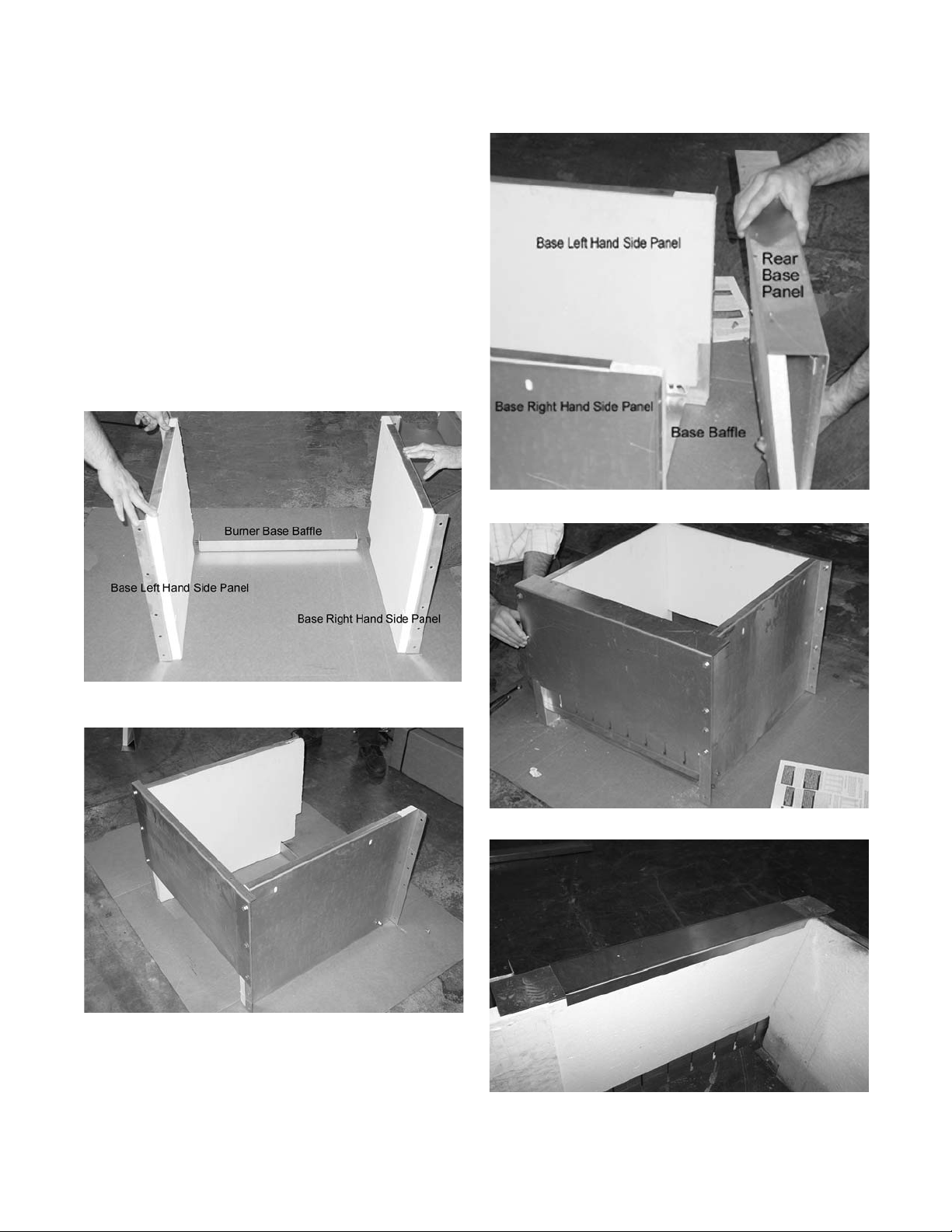
Burner Base Assembly 5 through 12 Sections
Loosely attach the base baffle to the side panels using 4
5/16 stainless steel nuts. Install the burner base front,
side and rear panels as shown in Figures 6, 7, 8 and
9A.
Use a spirit level to ensure that the burner base panels
are plumb before tightening the stainless steel nuts and
bolts.
The factory installed refractory retention bracket(s) must
be centered on each piece of refractory board Figure
9B. If the bracket is not centered reposition bracket.
There is (1) bracket for each section of refractory.
Figure 6 Burner Base Side Panels, 5 - 12
Figure 8
Figure 9A Burner Base Rear Panel, 5 - 12 Sect
Burner Base Rear Panel Detail, 5 - 12 Sect
Figure 7
Burner Base Front Panel, 5 - 12 Sect
Figure 9B Refractory Retension Bracket
GB300 BOILER INSTALLATION AND OPERATION INSTRUCTIONS
Page 13
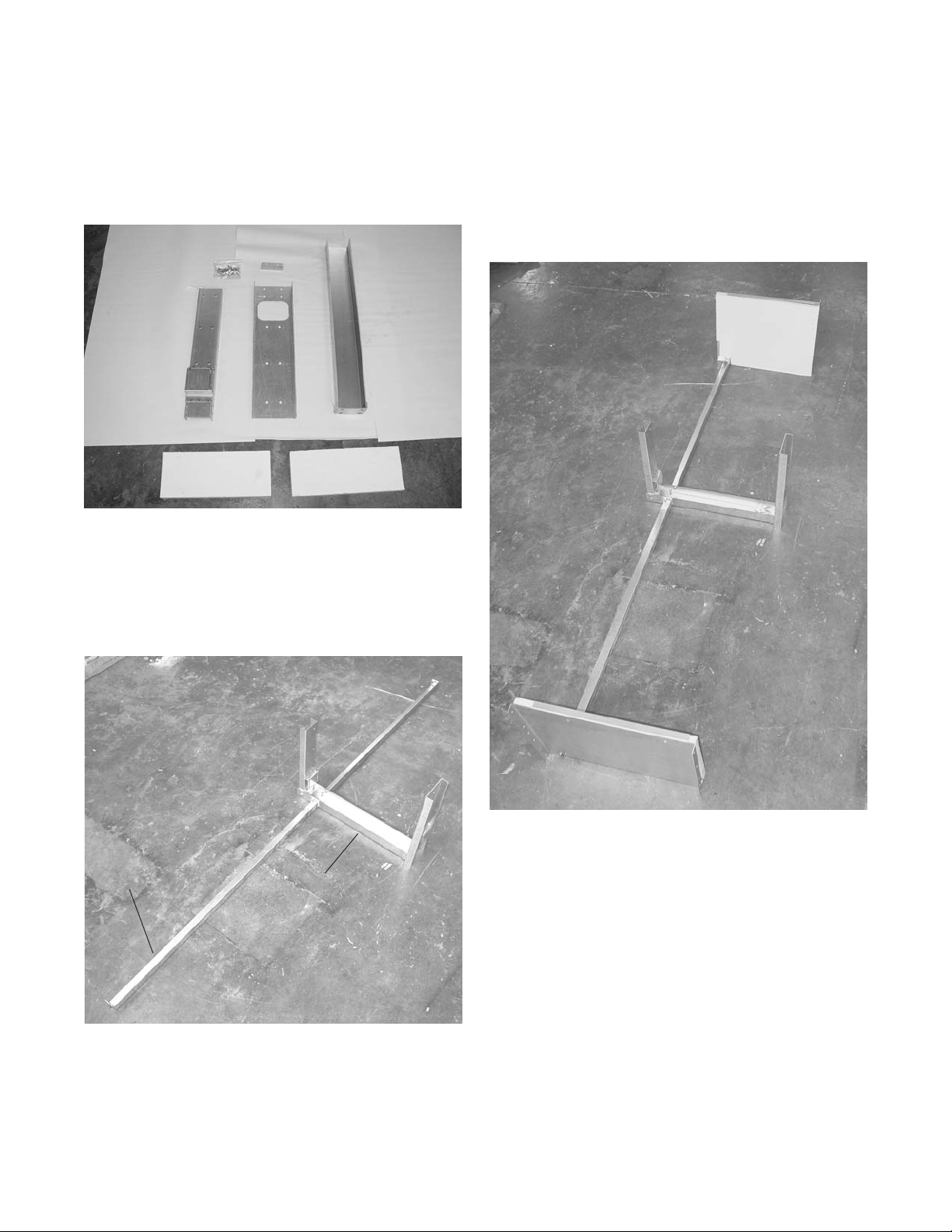
Burner Base Assembly 13 through 21 Sections
Box 72694, X7 Splice Channels, contains the burner
base front, intermediate and rear channels and
additional 5/16" nuts and bolts, Figure 10.
Figure 10 X7 Box 72694
The base baffles must be attached to the intermediate
base channel before the side, front and rear panels are
assembled, Figure 11.
With the burner base intermediate channel and baffles
level, attach the front and rear channels to the
intermediate channel. Bolt the burner base side panels
to the base baffles, Figure 12.
Figure 12 Burner Base Baffle Front and Rear
Splice Channel Assembly
13 to 21 Sections
Figure 11
Base Baffle
Burner Base Baffle and Intermediate
Splice Channel Assembly
13 to 21 Sections
•
Intermediate
Splice Channel
•
Page 14
GB300 BOILER INSTALLATION AND OPERATION INSTRUCTIONS
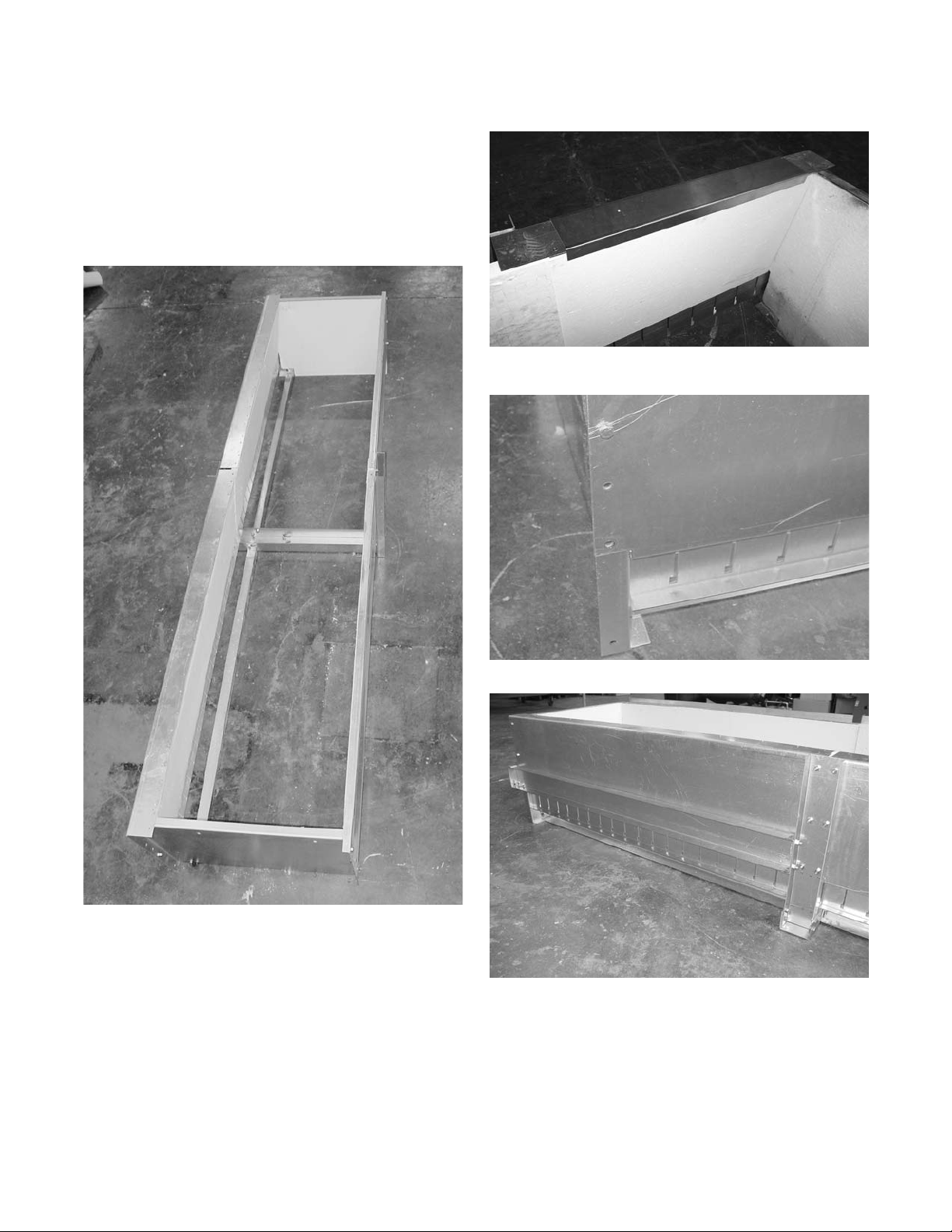
Bolt the front and rear base panels in place, Figure 13.
Center the factory installed refractory retention brackets
on the rear base panel so that the bracket is in the middle
of each refractory board Figure 13B.
Figure 13A Burner Base, Side Front and Rear
13 to 21 Sections Panel Assembly
Figure 13B
Figure 14A Base Rear Channel Bolt Holes
Figure 14B Base Rear Channel
NOTE: Do not install the two lower bolts in the base
rear panel, Figure 14A. These holes are used to attach
the base rear channel on 6 -12 section rear panels
and 13-21, Figure 14B.
GB300 BOILER INSTALLATION AND OPERATION INSTRUCTIONS
Page 15
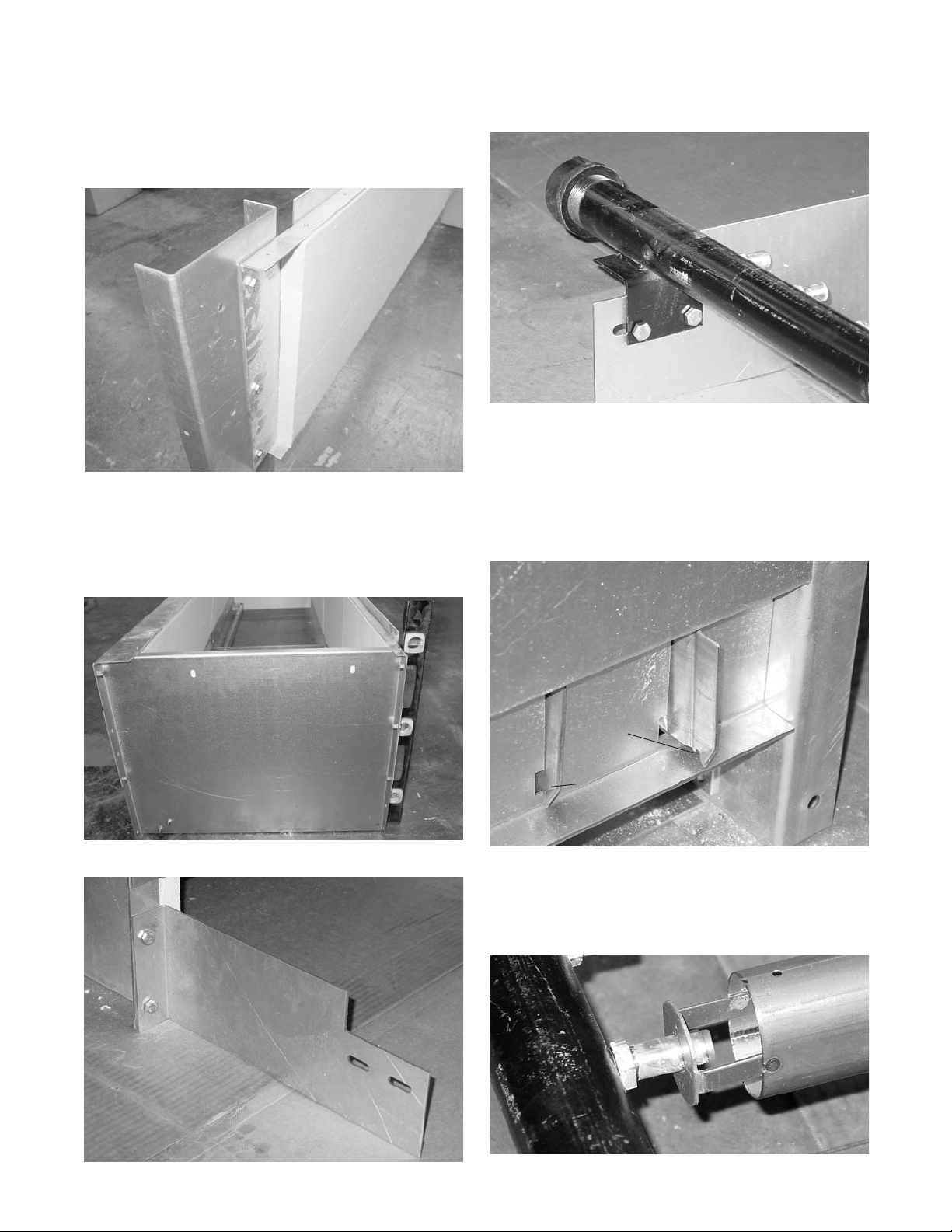
NOTE: The base front panels bolt to the inside of the
front base splice channel, Figure 15.
Figures 15 Base Front Panel Detail
Use a spirit level to plumb the front and rear panels
before tightening the nuts and bolts, Figure 16.
Temporarily attach the manifold brackets and manifold,
Figures 17 and 18.
Figure 18 Manifold Attachments
Locate the Burner Box. It is marked with a number from
72724 to 72731. Install three burner tubes in the base,
one on each end and one in the middle. Slide the closed
end of the burner tube through the slot in the burner
base rear panel. The notch in the burner must engage
the burner base rear panel, Figure 19.
Figure 19 Burner Tube Installation
Figure 16 Plumbing Base
Figure 17 Manifold Bracket Attachment
Notch
•
Notch
•
Engaged
Adjust the manifold and base so the burner tube orifice
bracket is approximately in the middle of the orifice on
all three burners, Figure 20.
Figure 20 Burner Tube Adjustment
Page 16
GB300 BOILER INSTALLATION AND OPERATION INSTRUCTIONS
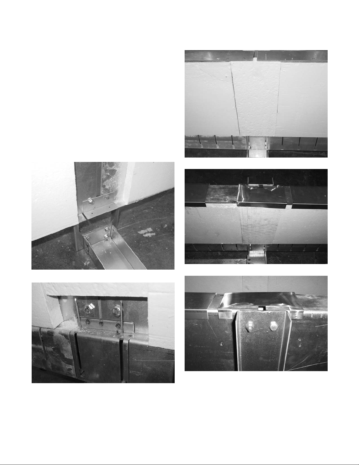
Bolt the insulation splice panel bracket to the front base
channel, Figure 21. Install the two insulation boards in
the spaces between the two front and two rear burner
base panels. Firmly but carefully press the insulation
boards in place and insert the nails through the top and
bottom holes, Figure 22A&B.
Orientate and install splice refractory retainer. Center the
retainer over the splice refractory and mating base
panels. The retainer should fit snuggly with the flat edge
on the outside of the base and the angled edge mating
flush to the refractory. Once insulation boards are
installed, slide the retention bracket over the top of the
base splice as shown in Figures 22C and 22D. Tighten
all bolts in base.
Figure 21 Burner Base Splice Panel Bracket
Figure 22B Burner Base Splice Insulation Boards
Figure 22C
Figure 22A Burner Base Splice Insulation Boards
Figure 22D
NOTE: Check all of the bolts in the base to ensure
they are tight before removing the burner tubes and
manifold.
 Loading...