

Smith Cast Iron Boilers GB250 User Manual
GB250-IM-5
42-9185
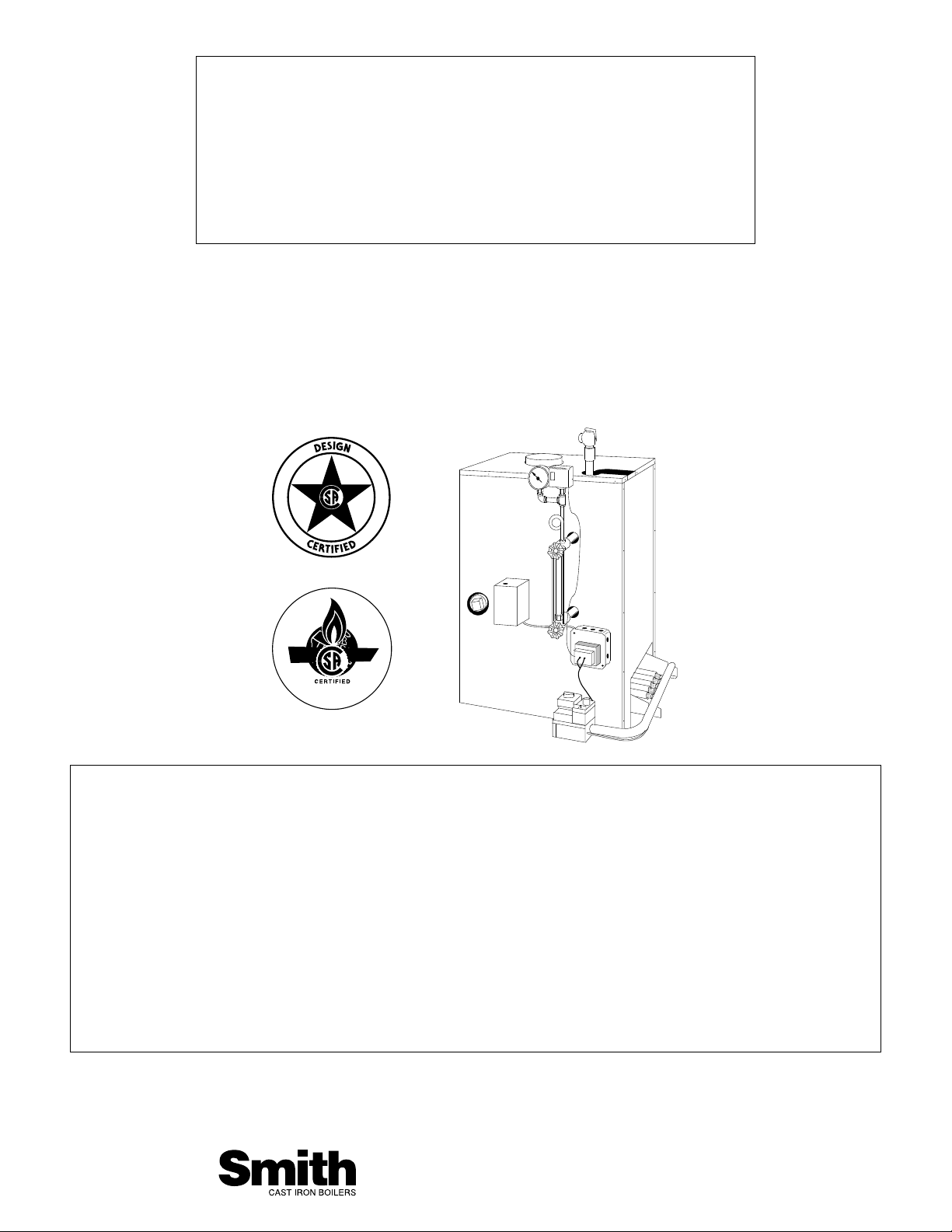
GB250 SERIES
INSTALLATION, OPERATION
& MAINTENANCE MANUAL
AND REPLACEMENT PARTS LIST
Gas-Fired Steam Cast Iron Boilers
175,000 to 400,000 Btuh Input
Standing Pilot, Standing Pilot & Vent Damper,
Intermittent Pilot, Intermittent Pilot & Vent
Damper
SECTION 1: INTRODUCTION
Code Compliance. ....................................................2
Venting Requirements ..............................................3
Chimney Requirements ............................................3
Combustion Air Requirements..................................3
Water Treatment........................................................4
Shipment of Boiler ....................................................4
SECTION 2: BOILER INSTALLATION
Step 1: Locating/Setting Boiler..................................5
Step 2: Installing Steam Piping ................................6
Step 3: Installing Hydronic Components ..................7
Step 4: Venting Boiler................................................7
Step 5: Installing/Testing Gas Piping ......................10
Step 6: Wiring Boiler ..............................................11
SECTION 3: START-UP & OPERATION
Sequence Of Operation..........................................16
Prior To Start-Up ....................................................16
Start-Up & Adjustments ..........................................16
SECTION 4: MAINTENANCE
Before Each Heating Season..................................19
How To Change Orifices ........................................20
Heating System Problems & Causes......................20
Replacement Parts List ..........................................21
Warnings ................................................................25
WESTCAST, INC.
260 NORTH ELM STREET WESTFIELD, MA 01085
TEL. (413) 562-9631 FAX (413) 562-3799
www.smithboiler.com
CODE COMPLIANCE
Boiler installations must conform to the requirements of
the authority having jurisdiction or, in the absence of
such requirements, to the National Fuel Gas Code ANSI
Z223.1-latest edition. Where required by the authority
having jurisdiction, the installation must also conform to
the Standard for Controls and Safety Devices for
Automatically Fired Boilers, ANSI/ASME CSD-1.
All electrical wiring must be in accordance with National
Electric Code ANSI/NFPA No.70-latest edition and any
additional state or local code requirements. If an
external source is utilized, boiler, when installed, must
be electrically grounded in accordance with
requirements of the authority having jurisdiction or, in
the absence of such requirements, with the National
Electrical Code, ANSI/NFPA No.70-latest edition. UL
listed power limited circuit cable is almost universally
approved for safety controls on heating equipment,
either internally or externally, without protection of
conduits or raceway.
For Canada, the installation must be in accordance with
Standards CGA B149.1 and B149.2 Installation Codes
for Gas Burning Appliances and Equipment and/or local
codes. All electrical connections are to be made in
accordance with Standard C.S.A. C22.1 Canadian
Electrical Code, Part 1 and/or local codes.
2
DANGER: Indicates an imminently hazardous
situation which, if not avoided, will result in death,
serious injury or substantial property damage.
WARNING: Indicates a potentially hazardous
situation which, if not avoided, could result in
death, serious injury or substantial property
damage.
CAUTION: Indicates a potentially hazardous
situation which, if not avoided, may result in minor
injury or property damage.
The following terms are used throughout this manual to bring attention to the presence of potential hazards or to
important information concerning the product:
NOTE: Used to notify of special instructions on
installation, operation or maintenance which are
important to equipment but not related to
personal injury hazards.
SECTION 1: INTRODUCTION
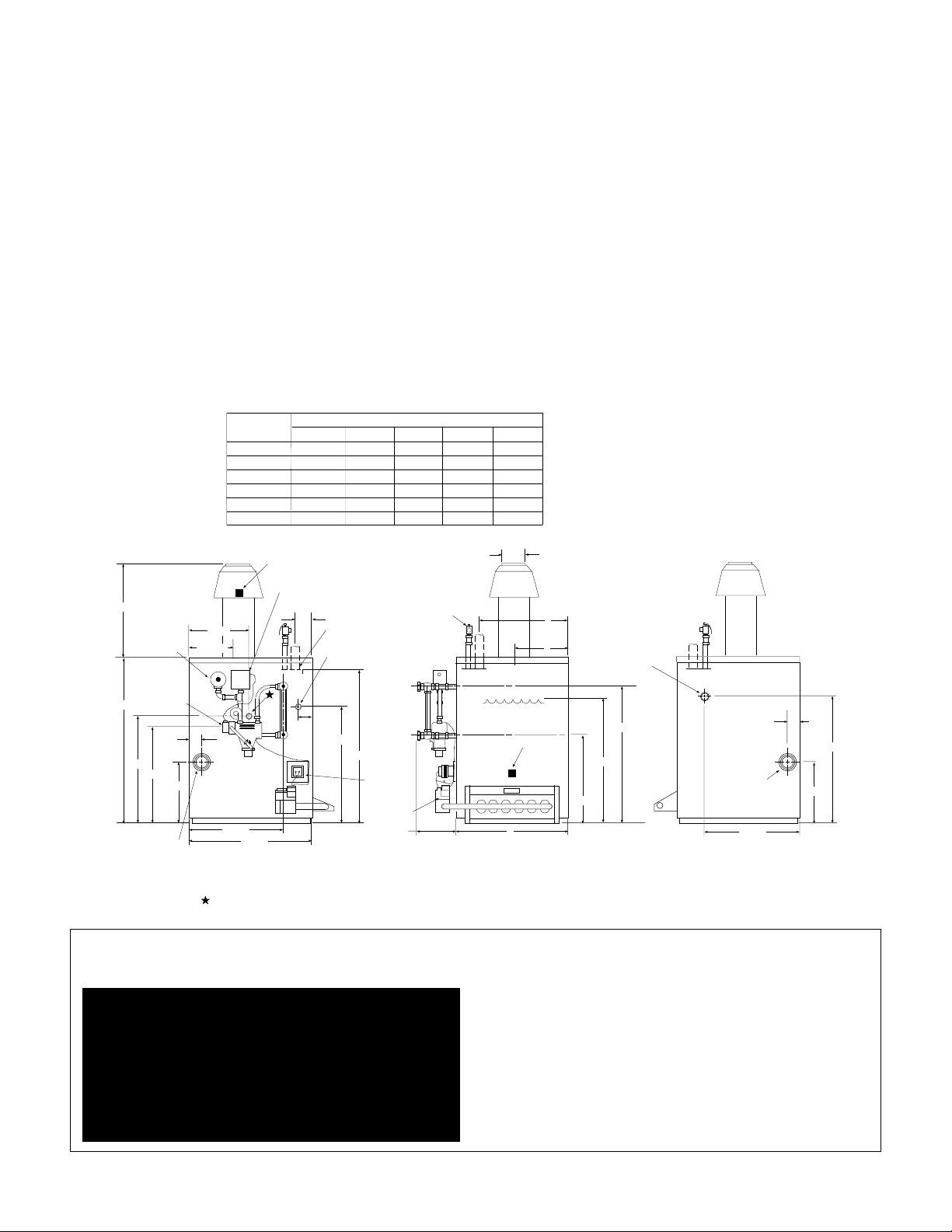
21 1/2"
28 1/2"
DIMENSIONS
B
18"
18"
25"
TRANSF.
115/24V
GAS VALVE
C
10 1/2" 7" 25"
10 1/2" 7" 25"
12 1/2" 8" 30"
14" 8" 30"
15 1/2"
17 1/2" 9" 37"
PRESSURE
RELIEF VALVE
*E
31 1/2"
PRESS.
GAUGE
LOW
WATER
CUT-OFF
2 1/2"
21"
20"
14 3/4"
2" RETURN
FRONT
BOILER
MODEL
GB250-S-5L
GB250-S-5H
GB250-S-6
GB250-S-7
GB250-S-8
GB250-S-9
SPILL SWITCH
9 3/8"
8 15/16"
16 1/2"
21 7/8"
-LEFT SIDE VIEW- -FRONT VIEW- -RIGHT SIDE VIEW-
A
22 1/2"
22 1/2"
26"
29 1/2"
29 1/2" 28 1/2"
36 1/2" 32"
PRESSURE CONTROL
3"
3" STEAM
SUPPLY
1/2" PLUGGED
TAPPING
3 3/4"
23 1/4"
FOR MODELS SUPPLIED WITH VENT
D
9"
E
37"
D
WATER
LINE
ROLLOUT SWITCH
A6 3/4"
DAMPER ADD 3 5/8" TO DIM. E
B
C
18 1/4"
3/4" PLUGGED
TAPPING
26 7/8"
23 1/4"
2" RETURN
REAR
18 1/8"
2 1/2"
14 3/4"
23 7/8"
PROBE LOCATION
FOR ELECTRIC
LWCO.

VENTING REQUIREMENTS
When connecting to gas vents or chimneys, vent installations shall be in accordance with Part 7, Venting of
Equipment, of the National Fuel Gas Code, ANSI
Z223.1-latest edition, or applicable provisions of the
local building codes. For Canada, the provisions of
B149.1 and B149.2 shall apply.
Vent connectors serving appliances vented by natural
draft shall not be connected into any portion of mechanical draft systems operating under positive pressure.
When two or more appliances vent into a common flue,
the area of the common flue should be at least equal to
the area of the largest flue plus 50% of the areas of the
additional flue or vent connectors.
When an existing boiler is removed from common
venting system, common venting system is likely to be
too large for proper venting of appliances remaining
connected to it. At time of removal of existing boiler, the
following steps shall be followed with each appliance
remaining connected to the common venting system
placed in operation, while other appliances remaining
connected to the common venting system are not in
operation:
1. Seal all unused openings in common venting system.
2. Visually inspect the venting system for proper size
and horizontal pitch and determine there is no blockage
or restriction, leakage, corrosion and other deficiencies
which could cause an unsafe condition.
3. Insofar as is practical, close all building doors and
windows and all doors between the space in which the
appliances remaining connected to the common venting
system are located and other spaces of the building.
Tur n on clothes dr yers and any appliance not connected
to the common venting system. Turn on any exhaust
fans, such as range hoods and bathroom exhausts, so
they will operate at maximum speed. Do not operate a
summer exhaust fan. Close fireplace dampers.
4. Place in operation the appliance being inspected. Follow the lighting instructions. Adjust thermostat so
appliance will operate continuously.
5. Test for spillage at draft hood relief opening after 5
minutes of main burner operation. Use the flame of a
match or candle, or smoke from cigarette, cigar or pipe.
6. After it has been determined that each appliance
remaining connected to common venting system properly vents when tested as outlined above, return doors,
windows, exhaust fans, fireplace dampers and any other
gas-burning appliance to previous conditions of use.
7. Any improper operation of the common venting system should be corrected so the installation conforms
with National Fuel Gas Code, ANSI Z223.1-latest
edition. When resizing any portion of the common
venting system, the common venting system should be
resized to approach the minimum size as determined
using the appropriate tables in Appendix G in the
National Fuel Gas Code, ANSI Z223.1-latest edition.
For Canada, the provisions of B149.1 and B149.2 shall
apply.
CHIMNEY REQUIREMENTS
Chimney condition is of paramount importance for a
safe and efficient boiler installation. All new and replacement installations must include a chimney inspection by
a qualified individual or agency. Chimney construction
materials must be compatible with the fuel being used.
Particular attention should be paid on all oil-to-gas conversions. Soot may have accumulated in chimney and/or
degraded chimney liner. Most utilities require complete
chimney cleaning. Others may require installation of new
liner, spill switches or other chimney upgrades. Check
with local utility for required safety precautions.
COMBUSTION AIR REQUIREMENTS
Provisions for combustion air must be in accordance
with the National Fuel Gas Code ANSI Z223.1 - latest
edition, as well as all applicable local codes. If the boiler
is installed in an unconfined space, adequate air will be
available via normal infiltration. However, if building
construction is unusually tight or the boiler is installed in
a confined space (a space whose volume is less than 50
cubic feet per 1000 Btu/hr of gas input for all fuel
burning equipment), adequate air for combustion must
be provided by two openings: one located about 6”
below the ceiling, the other about 6” above the floor.
When communicating directly with the outside or
through a vertical duct, each opening must have a
minimum free area of one square inch per 4000 Btu/hr
of gas input. Horizontal ducts to the outside must have a
minimum free area of one square inch per 2000 Btu/hr
of gas input. When ventilation is provided by openings in
doors, etc. to adjoining spaces having adequate
infiltration, each opening must have a minimum free
area of one square inch per 1000 Btu/hr of gas input.
3
DANGER: A chimney which does not meet modern
safety standards will result in a fire or deadly carbon
monoxide poisoning of the building residents.

4
NOTE: Boiler employs atmospheric combustion.
Combustion air must not be contaminated with
halogenated hydrocarbon vapors, aerosol
propellants or freon. Otherwise, boiler heat
exchanger will be subject to corrosion, reducing
boiler life.
WATER TREATMENT
Water treatment is recommended in areas where water
quality is a problem. A local water treatment company
should be consulted to determine the requirements for
your particular system and locality.
NOTE: Boiler is not for use in systems where water
is replenished. Minerals in the water can build up on
the heat transfer surfaces and cause overheating
and subsequent failure of the heat exchanger.
NOTE: Boiler utilizes synthetic rubber seals. Water
treatment chemicals and system cleaning chemicals
must be compatible with this and all other
construction materials.
SHIPMENT OF BOILER
Each boiler is shipped in a single carton. Draft hood is
shipped in a separate carton on larger models.
Optional Vent Damper
When ordered, the vent damper is shipped in an
individual carton packaged with the boiler. Mounting of
the damper is required.
WARNING: Adequate fresh air must be provided for
combustion. Improper boiler operation and
inadequate venting of deadly flue gases may
otherwise result.
WARNING: Installers must follow local regulations
with respect to the installation of CO detectors and
follow the manufacturer’s stated maintenance
schedule for this boiler!
ATTENTION: Observer les règlements règional à
l’egard des détecteurs de monoxyde de carbone et
observer entretien de manufacturier pour cette
chaudière!
SECTION 2: BOILER INSTALLATION
STEP 1: LOCATING AND SETTING THE BOILER
➤PROCEDURE A: Check that provisions for combustion air are in accordance with National Fuel Gas
Code ANSI Z223.1-latest edition and all applicable local codes. In Canada, follow CAN/CGA B149(.1 or .2)
installation codes.
➤PROCEDURE B:
Check minimum
clearances to
combustibles are
proper as shown. Local
requirements may
specify greater
clearances & must be
adhered to.
Boiler shall be installed such that the gas
ignition system components are protected
from water (dripping,
spraying, rain, etc.)
during appliance operation and service.
WARNING: Never install boiler on combustible flooring without combustible flooring pan or on carpeting
as heat damage and/or fire may result.
FIGURE 2.1
5
Step 1 Continued On Next Page
NOTE: Do not loosen tie rods on absorption unit. They accommodate thermal expansion. Loss of boiler
structural integrity and water leaks/damage may result.
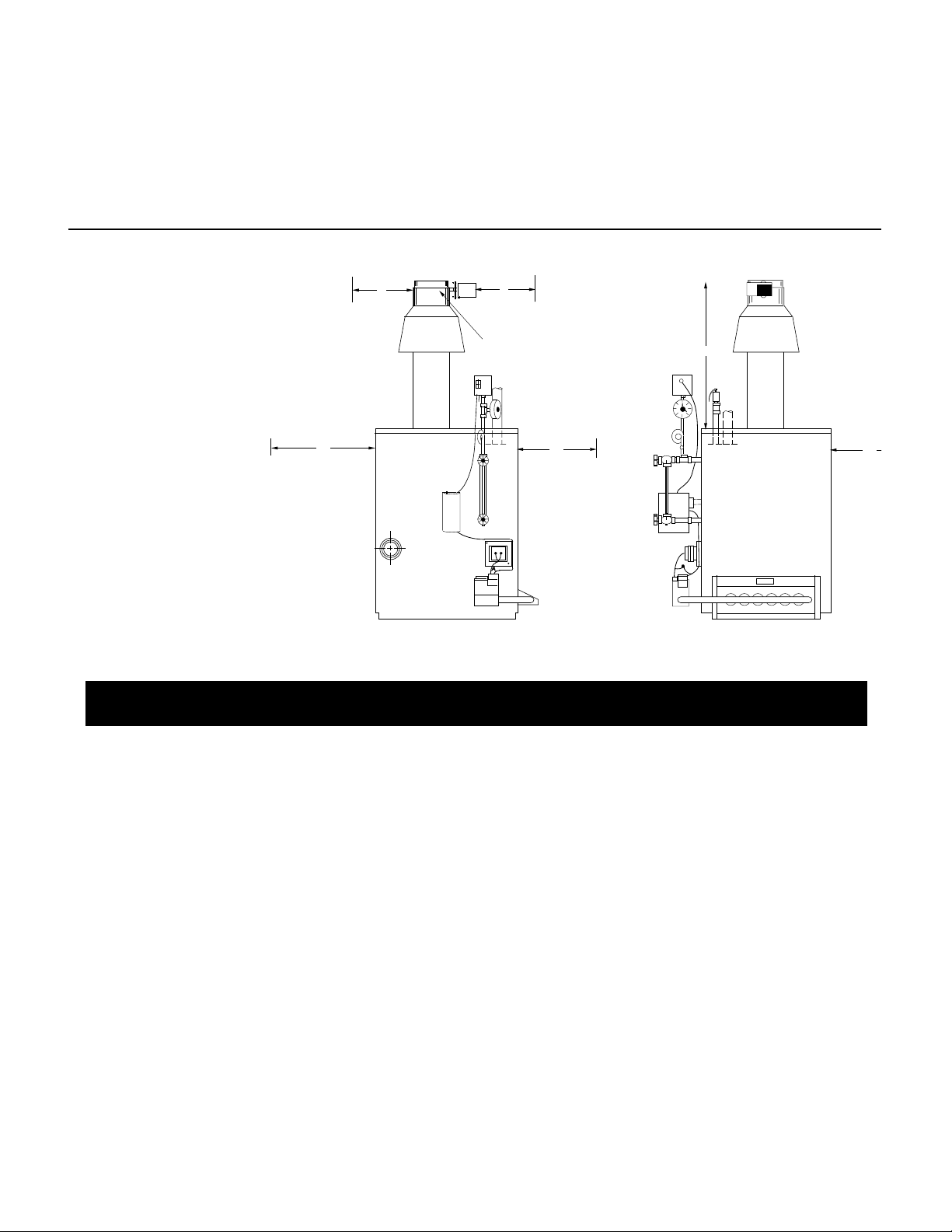
CAUTION: Locate boiler so horizontal connecting flue pipe is as short as possible. Maximize height of
vertical flue connector.
6"
6"
VENT DAMPER
* TOP
18"
1
1
1
1
1
1
1
1111
1
1
12"
RECOMMEND
MORE FOR
ACCESS TO
VENT DAMPER
POSITION
INDICATOR
* 52" FOR GB250-S-5L THRU GB250 S-7
58" FOR GB250-S-8 THRU GB250-S-9
12"
6
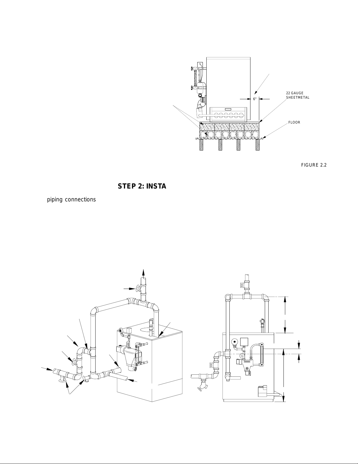
➤PROCEDURE C:
Check component positioning.
1. Remove all packing material
from boiler.
2. Install on non-combustible floor
only, unless local codes permit
use and fabrication of a fireproof
base (see Fig. 2.2).
3. Check that burners and controls
are in the proper position.
FIGURE 2.2
STEP 2: INSTALLING STEAM PIPING
Typical piping connections are shown in Figure 2.3. All
external piping must be supported by hangers, not by
the boiler or its accessories.
Supply outlet must run full size from boiler to a header at
least 24" above top of boiler. Condensate return piping
should be connected to boiler through a "Hartford Loop."
Install gate valves in supply and return.
Proper steam piping practices must be followed at all
times. Maintain proper clearances between piping and
combustible material.
The supply and return lines should be equipped with
drain cocks to drain sediment and sludge from lowest
points of boiler.
FIGURE 2.3
4" HOLLOW CLAY TILE (TWO
COURSES) OPENINGS THRU
BLOCKS IN TOP COURSE TO
0
BE AT 90 ANGLE TO OPENINGS
THRU BOTTOM COURSE
6" OVERHANG OF BLOCK AND
SHEETMETAL ALL AROUND
6"
22 GAUGE
SHEETMETAL
FLOOR
STEAM
SUPPLY
GATE VALVE
SUPPLY
TAPPING
3" NPT
HARTFORD
LOOP
RETURN
MUST BE CLOSE
NIPPLE
GATE
VALVE
DRAIN
COCKS
RETURN
TAPPING
2" NPT
COLD WATER FILL
24" MIN.
WATER LINE
C/L OF HARTFORD
LOOP TO BE 2"
BELOW WATER
LINE
23-1/4"
7
STEP 3: INSTALLING HYDRONIC COMPONENTS
A low-water cutoff must be installed to protect the unit
from dry-fire.
Screw extension nipple into 3/4" tapping on top of the
absorption unit and install relief valve into top of nipple
with the spindle in the vertical position (i.e., with the
valve discharge in the horizontal)(See Figure 2.4).
Most localities require the discharge piping to terminate
within 6" of the floor. Check local code requirements if in
doubt. Discharge piping must be of same size or larger
than the relief valve outlet and should be run as short
and straight as possible. Elbows in the discharge piping
should be placed as close to the valve as possible. If
valve discharge is to be drained away, the discharge
piping must not be hard-piped to the drain piping (i.e.,
an open funnel or similar arrangement must be used).
FIGURE 2.4
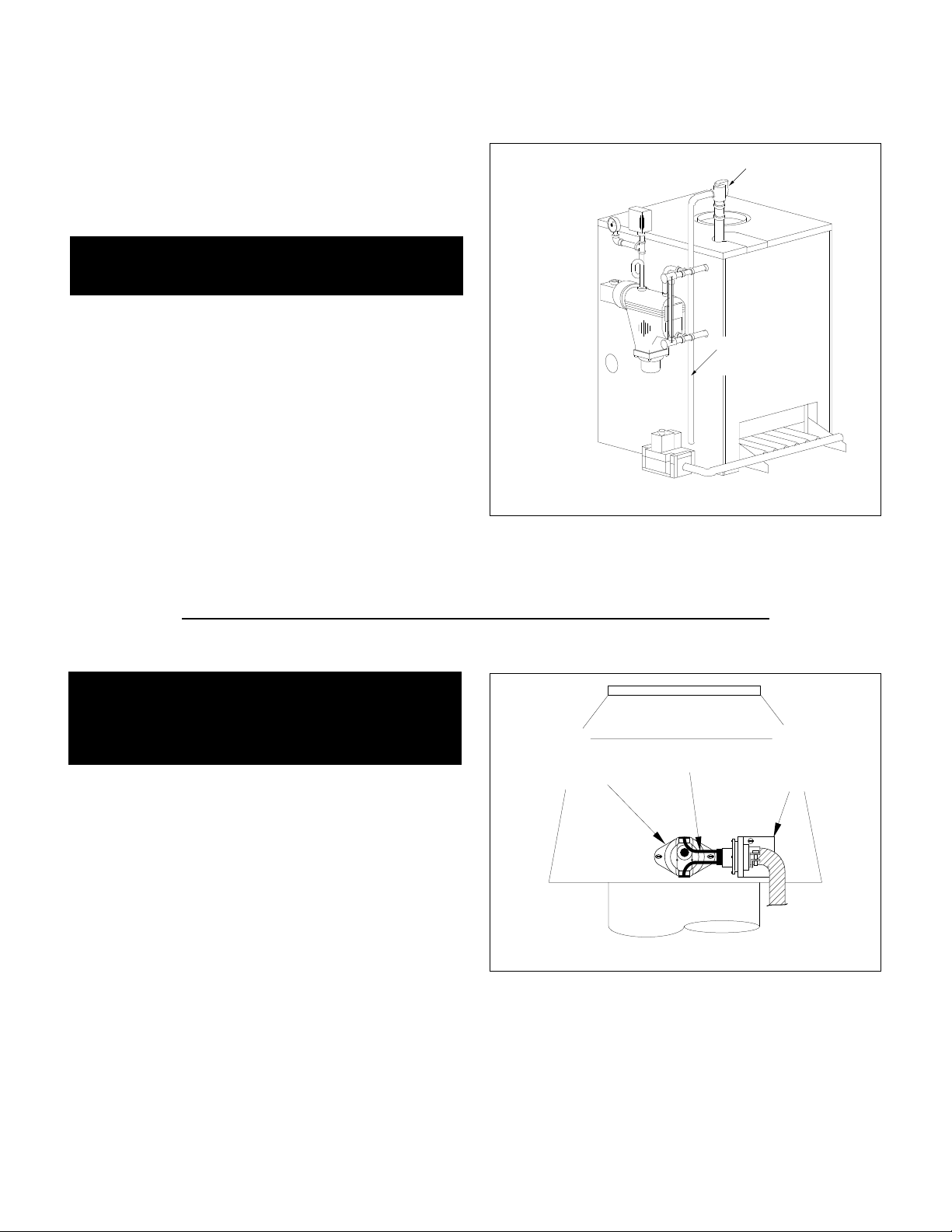
STEP 4: VENTING BOILER
Install draft hood on boiler. If the draft hood shroud has a
hole near the relief opening for installing a spill switch,
mount draft hood so the hole faces to the front of the
boiler. Spill switches are provided on Model GB250-5L,
GB250-5H, and GB250-6 boilers.
Applicable boiler is equipped with a factory-mounted
spill switch harness/mounting bracket assembly; spill
switch is provided in plastic bag. See Figure 2.5. Install
mounting bracket on outside surface of draft hood
shroud with screws provided (HARNESS MUST BE ON
OUTSIDE OF SHROUD). Install spill switch in hole in
shroud (on outside surface) with screws provided. Plug
wiring leads from harness/bracket assembly onto flat
terminals on spill switch.
NOTE: Boiler will not operate unless wiring leads to
spill switch are connected.
FIGURE 2.5
If vent damper is supplied with boiler, it must be installed
between the top of the draft hood and the flue pipe. See
“Installing The Vent Damper” instructions.
Connect draft hood to chimney or Class B vent. Flue
pipe must be same diameter as the draft hood outlet.
WARNING: No Valve of any type may be installed
between the boiler and the relief valve to prevent
accidental explosion from overpressure.
DANGER: Drafthood, vent outlet and vent damper as
supplied must not be altered in any was as proper
boiler operation would be jeopardized. Flame
rollout, fire or carbon monoxide poisoning will
result.
CAUTION: Piping must be installed from the relief
valve discharge so there will be no danger of
scalding personnel.
PRESSURE
RELIEF VALVE
PRESSURE RELIEF
VALVE DISCHARGE
PIPING
INSTALL
SWITCH
IN OPENING
ON DRAFTHOOD
CONNECT
WIRE
LEADS
INSTALL
MOUNTING
BRACKET
ON DRAFTHOOD
8
The flue or vent connectors must be installed flush with
the inside chimney liner surface and sealed in place with
furnace cement. Horizontal portions of the single wall
and type B venting systems shall be supported by use
of strap hangers or their equivalent. Vent suppor ts
should be placed a maximum of 15-feet apart and as
required to prevent sagging. The vent connectors shall
be pitched 1/4" per foot upwards towards the chimney or
vent termination.
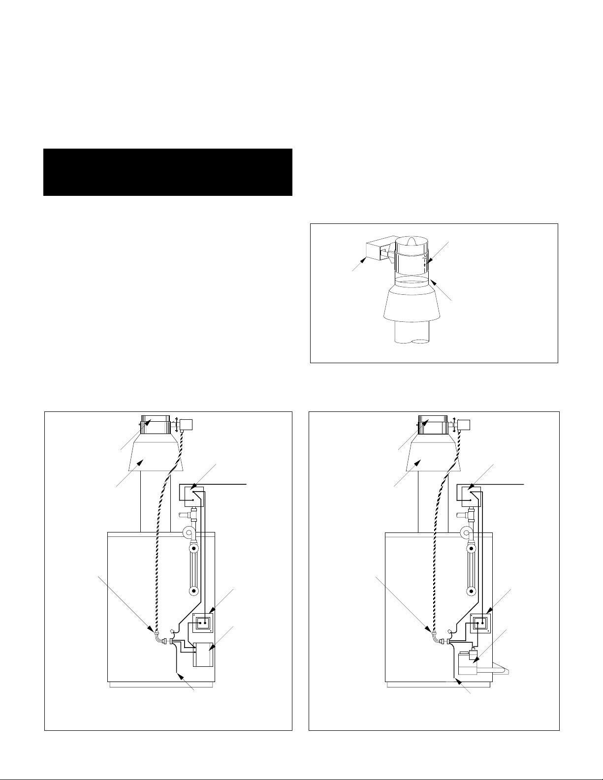
Installing Vent Damper
The vent damper must be mounted directly on top of the
draft hood.
Locate the motor on the front side and position the cable
so that it does not touch the metal surface of the
drafthood (see Figure 2.6). If necessary, turn angle
connector on vent damper upward until cable clears;
tighten locknut to secure.The direction of the flow arrow
imprinted on the vent damper must point upward. The
damper position indicator, which is located on the side
of the vent damper opposite the motor, must be visible.
Remove hairpin shipping clip which holds damper blade
in closed position and observe that damper blade
rotates slowly to open position. Do not force it closed as
it may damage the gear train and void the warranty. The
blade should move freely and without obstruction.
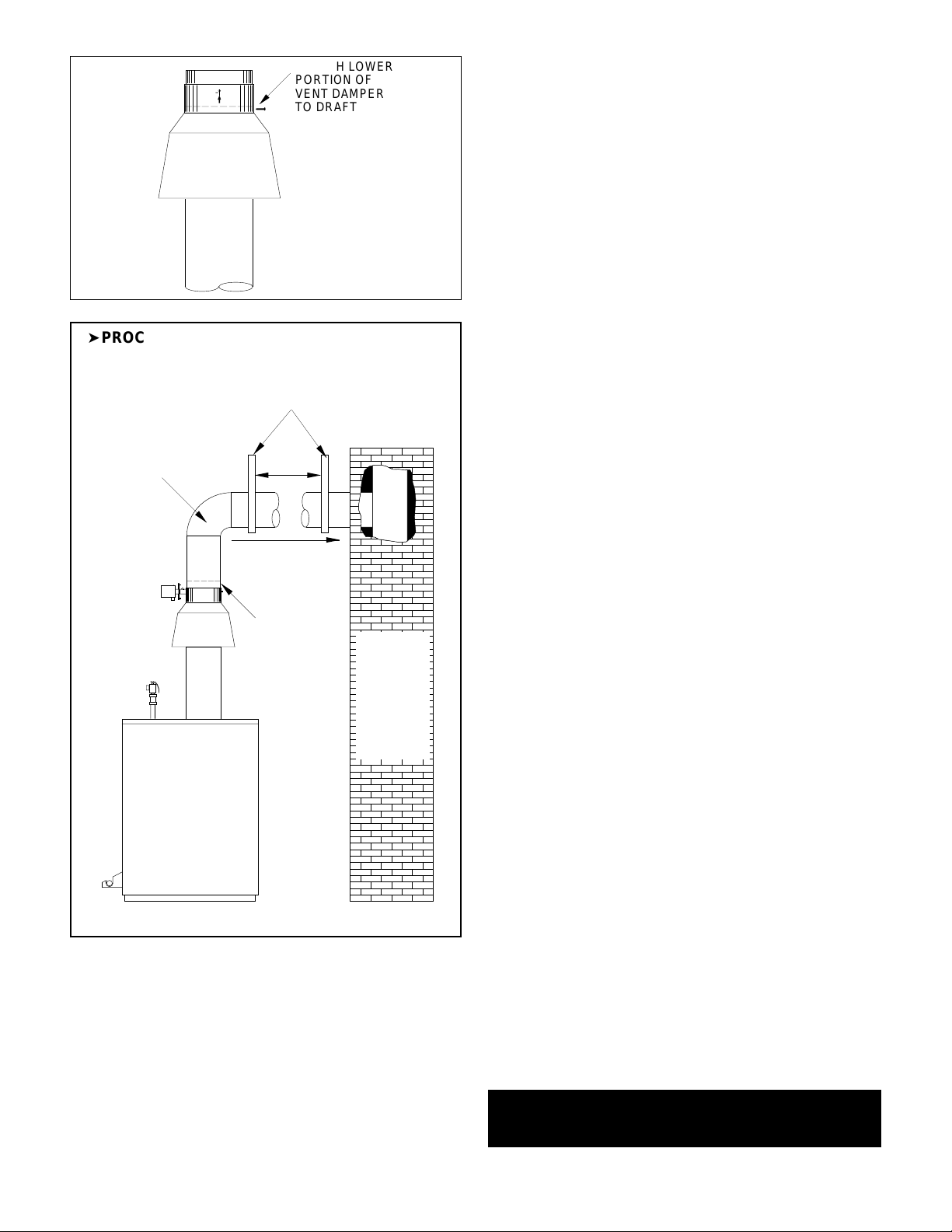
Secure the vent damper housing to the drafthood outlet
with sheet metal screws or pop rivets. Refer to Figure
2.8 for fastener locations. Install flue pipe over top of
vent damper and secure to damper housing with sheet
metal screws or pop rivets.
Attach vent damper cable to cable clamp on boiler left
panel and join the Molex connector (see Figure 2.6 or
Figure 2.6A).
FIGURE 2.6: Vent Damper Installation for Intermittent Pilot
FIGURE 2.7
DANGER: Only the boiler may be served by the vent
damper. Do not attempt to use it to vent an
additional appliance. This will cause fire or carbon
monoxide poisoning.
CAUTION: A minimum of 6" between vent damper
and combustible materials must be maintained. The
vent damper must be accessible for servicing and
checking position indicator.
R
FIGURE 2.6A: Vent Damper Installation for Standing Pilot
FLOW DIRECTION
ARROW POINTS UP
MAKE SURE
MOTOR IS
LOCATED ON
FRONT SIDE
MOUNT VENT
DAMPER OVER
DRAFTHOOD
VENT DAMPER
DRAFTHOOD
CABLE
BRACKET
PRESSURE
CONTROL
THERMOSTAT
CONNECTION
TRANSFORMER
PILOT CONTROL
VENT DAMPER
DRAFTHOOD
CABLE
BRACKET
PRESSURE
CONTROL
THERMOSTAT
CONNECTION
TRANSFORME
GAS VALVE
DK. BLUE
THERMOSTAT CONNECTION
DK. BLUE
THERMOSTAT CONNECTION
9
ADDITIONAL VENTING REQUIREMENTS: When connecting
to gas vents or chimneys, vent installations shall be in
accordance with Part 7, Venting of Equipment, of the National
Fuel Gas Code, ANSI Z223.1-latest edition, or applicable
provisions of the local building codes.
Vent connectors serving appliances vented by natural draft
shall not be connected into any portion of mechanical draft
systems operating under positive pressure.
When two or more appliances vent into a common flue, the
area of the common flue should be at least equal to the area
of the largest flue plus 50% of the areas of the additional flue
or vent connectors.
When an existing boiler is removed from a common venting
system, common venting system is likely to be too large for
proper venting of appliances remaining connected to it. At time
of removal of existing boiler, following steps shall be followed
with each appliance remaining connected to the common
venting system placed in operation, while other appliances
remaining connected to common venting system are not in
operation:
1. Seal all unused openings in common venting system.
2. Visually inspect the venting system for proper size and
horizontal pitch and determine there is no blockage or
restriction, leakage, corrosion and other deficiencies which
could cause an unsafe condition.
3. Insofar as is practical, close all building doors and windows
and all doors between the space in which the appliances
remaining connected to the common venting system are
located and other spaces of the building. Tur n on clothes
dryers and any appliance not connected to the common
venting system. Tur n on any exhaust fans, such as range
hoods and bathroom exhausts, so they will operate at
maximum speed. Do not operate a summer exhaust fan. Close
fireplace dampers.
4. Place in operation the appliance being inspected. Follow the
lighting instructions. Adjust thermostat so appliance will
operate continuously.
5. Test for spillage at draft hood relief opening after 5 minutes
of main burner operation. Use the flame of a match or candle,
or smoke from cigarette, cigar or pipe.
6. After it has been determined that each appliance remaining
connected to common venting system properly vents when
tested as outlined above, return doors, windows, exhaust fans,
fireplace dampers and any other gas burning appliance to
previous conditions of use.
7. Any improper operation of the common venting system
should be corrected so installation conforms with the National
Fuel Gas Code, ANSI Z223.1-latest edition. When resizing any
portion of the common venting system, the common venting
system should be resized to approach the minimum size as
determined using the appropriate tables in Appendix G in the
National Fuel Gas Code, ANSI Z223.1-latest edition. For
Canada, the provisions of CAN/CGA B149(.1 or .2) shall apply.
ADDITIONAL CHIMNEY REQUIREMENTS: Chimney
condition is of paramount importance for a safe and efficient
boiler installation. All installations must include a chimney
inspection by a qualified individual or agency. Chimney
construction materials must be compatible with the fuel being
used.
Particular attention should be paid on all oil-to-gas
conversions.Soot may have accumulated in chimney and/or
degraded chimney liner. Most utilities require complete
chimney cleaning. Others may require installation of new liner,
spill switches or other chimney upgrades. Check with local
utility for required safety precautions.
➤PROCEDURE C: Install flue pipe between vent
damper and chimney (6" minimum clearance
required between flue pipe and combustibles).
FIGURE 2.9
DANGER: A chimney which does not meet modern
safety standards will result in a fire or deadly carbon
monoxide poisoning of the building residents.
A
A
ATTACH LOWER
FIGURE 2.8
PORTION OF
VENT DAMPER
TO DRAFTHOOD
OUTLET WITH 1/2"
OR SHORTER
SCREWS OR
POP RIVETS
AA
AA
USE VENT SUPPORT(S) AS REQUIRED TO PREVENT SAGGING
MAXIMUM
SINGLE WALL
OR TYPE B
FLUE PIPE
6 FT.
APART
PITCH 1/4" PER FOOT
SECURE
FLUE PIPE
TO VENT
DAMPER
INSTALL
FLUSH
WITH
CHIMNEY
LINER
SEAL
WITH
FURNACE
CEMENT
 Loading...