

Smith Cast Iron Boilers GB100W User Manual
GB100IOM-7
GB100W
NATURAL OR PROPANE GAS BOILER
INSTALLATION & OPERATING
INSTRUCTIONS
DESIGNED AND TESTED ACCORDING TO A.S.M.E. BOILER AND PRESSURE
VESSEL CODE, SECTION IV FOR MAXIMUM ALLOWABLE WORKING PRESSURE OF
50 PSI,
NOTE TO INSTALLING CONTRACTOR: READ THESE INSTRUCTIONS CAREFULLY.
THEY WILL SAVE YOU TIME IN ASSEMBLING BOILER PROPERLY.
345 kPa
WATER
WARNING: Installation and service must be performed by a qualified installer, service
agency or the gas supplier in accordance with all local and national codes. Failure to
comply with this warning can result in a fire or explosion causing property damage,
personal injury or loss of life!
WARNING: If the information in this manual is not followed
exactly, a fire or explosion may result causing property damge,
personal injury or loss of life.
Do not store or use gasoline or other flammable vapors and liquids
in the vicinity of this or any other appliance.
What to do if you smell gas:
• Do not try to light any appliance.
• Do not touch any electrical switch. Do not use any phone in your
building.
• Immediately call your gas supplier from a neighbor's phone. Follow
the gas supplier's instructions.
• If you cannot reach your gas supplier, call the fire department.
Installation and service must be performed by a qualified in
service agency or the gas supplier.
staller,
INSTALLER, THESE INSTRUCTIONS TO BE AFFIXED ADJACENT TO THE BOILER.
CONSUMER, RETAIN THESE INSTRUCTIONS FOR FUTURE REFERENCE PURPOSES.
WESTCAST, INC.
260 NORTH ELM STREET WESTFIELD, MA 01085
TEL. (413) 562-9631 FAX (413) 562-3799
In Canada: 7555 Tranmere Drive, Mississauga, Ont. L5S 1L4 (905) 672-2991 Fax (905) 672-2883

Page 2
GB100W NATURAL OR PROPANE BOILER
INSTALLATION AND OPERATING INSTRUCTIONS
AVERTISSMENT. Assurez-vous de bien suivre les instructions données dans cette
notice pour réduire au minimum le risque d’incendie ou d’explosion ou pour éviter
tout dommoge matériel, toute blessure ou la mort
Ne pas entreposer ni utiliser d’essence ou ni d’autres vapeurs ou liquides inflammables
à proximité de cet appareil ou de tout autre appareil.
QUE FAIRE SI VOUS SENTEZ UNE ODEUR DE GAZ:
• Ne pas tenter d’allumer d’appareil.
• Ne touchez à aucun interrupteur; ne pas vous servir des téléphones se trouvant dans
le bâtiment.
• Appelez immédiatement votre fournisseur de gas depuis un voisin. Suivez les
intructions du fournisseur.
• Si vous ne purvez rejoindre le fournisseur, appelez le service des incendies.
L’installation et l’entretien doivent être assurés par un installateur ou un service
d’entretien qualifié ou par le fournisseur de gaz.
CONTENTS
Getting Started page 2
Boiler Ratings & Capacities page 3
Locating the Boiler page 3
Combustible Floor Option page 5
Air for Combustion page 5
Chimney & Vent Pipe Connections page 6
Heating System Piping page 8
Gas Supply Piping page 11
Electrical Wiring page 12
Starting the Boiler page 18
Operating the Boiler page 20
Checking & Adjusting page 23
Boiler Maintenance page 24
Instructions to the Owner page 25
Replacement Parts page 26
Canadian Supplement page 28
Health Warnings page 30
BEFORE YOU START
WARNING: This manual must be read and fully
understood before installing, operating or
servicing this boiler! Failure to follow these
instruction could result in a fire or explosion
causing extensive property damage, personal
injury or death!
These instructions cover the GB100W gas fired, low
pressure, sectional, cast iron hot water boiler. GB100W
boilers have been design certified by CSA under the
latest revision of ANSI-Z21.13 for gas fired low pressure
steam and hot water boilers, for use with natural and
propane gas. Each unit has been constructed and
hydrostatically tested for a maximum working pressure
of 50 psi,
Boiler and Pressure Vessel Code, Section IV for cast
iron boilers. Each boiler has been equipped with a 30 psi
pressure relief valve.
This manual covers the application, installation,
operation and maintenance of a GB100W low pressure
hot water boiler.
To obtain the safe, dependable, efficient operation and
long life for which this boiler was designed, these
instructions must be read, understood and followed.
345 kPa
in accordance with the A.S.M.E.

GB100W NATURAL OR PROPANE BOILER
INSTALLATION AND OPERATING INSTRUCTIONS
Page 3
Direct all questions to your Smith Cast Iron Boiler
distributor or write to the Customer Service Department,
260 North Elm Street, Westfield, MA 01085. Always
include the model and serial numbers from the rating
plate of the boiler in question.
The owner should maintain a record of all service work
performed with the date and a description of the work
done. Include the name of the service organization for
future reference.
Where required by the authority having jurisdiction, the
installation must conform to the Standard for Controls
and Safety Devices for Automatically Fired Boilers,
ANSI/ ASME CSD-1.
The installation must conform to the requirements of
the authority having jurisdiction or, in the absence of
such requirements, to the National Fuel Gas Code,
ANSI Z223.1/NFPA 54-latest revision. In Canada,
installation must be in accordance with the requirements
of CAN/CGA B149.1 or 2 Installation Code for Gas
Burning Appliances and Equipment.
BOILER RATINGS AND CAPACITIES
Before undertaking the installation of the GB100W
check the boiler rating plate to ensure that the boiler is
the proper size for the job. The “Net I=B=R Ratings”
specify the equivalent amount of direct cast iron
radiation that the boiler can handle under normal
conditions. Also ensure that the boiler has been set up
for the type of gas available at the installation site.
Other important considerations are the availability of
an adequate electrical supply, fresh air for combustion
and a suitable chimney or vent system.
NOTES:
1. For altitudes above 2000 ft,
be reduced at the rate of 4% for each 1000 ft,
m
above sea level, 10% in Canada.
2. If ordering a boiler for use with LP gas add a P to
the model number, ie PGB100.
610 m
, ratings should
305
BOILER LOCATION
WARNING: This boiler is for installation on noncombustible floors only! A special base
supplied by the manufacturer must be used to
install this boiler on a combustible floor. Failure
to comply with this warning can result in
property damage, severe personal injury or
death!
1. Locate the boiler in an area that provides good
access to the unit. Keep in mind that servicing may
require the removal of jacket panels. Accessibility
clearances must take precedence over fire
protection clearances.
2. An optimum site will be level, central to the piping
system, close to a chimney and have adequate
fresh air for combustion.
3. Ensure that the floor is structurally sound and will
support the weight of the boiler. This boiler is
designed for non combustible floors only! A special
base supplied by Smith Cast Iron Boilers must be
used if the boiler is to be installed on a combustible
floor. NEVER USE A SUBSTITUTE BASE ON A
COMBUSTIBLE FLOOR! Never install this boiler on
carpeting!
4. DO NOT install this boiler in a location that would
subject any of the gas ignition components to direct
contact with water or excessive moisture during
operation or servicing.
5. DO NOT place this boiler in a location that would
restrict the introduction of combustion air into the
boiler. NEVER store objects on or around the boiler.
WARNING: Never store combustible materials,
gasoline or any product containing flammable
vapors or liquids in the vicinity of the boiler.
Failure to comply with this warning can result in
extensive property damage, severe personal
injury or death!
Page 4
GB100W NATURAL OR PROPANE BOILER
INSTALLATION AND OPERATING INSTRUCTIONS
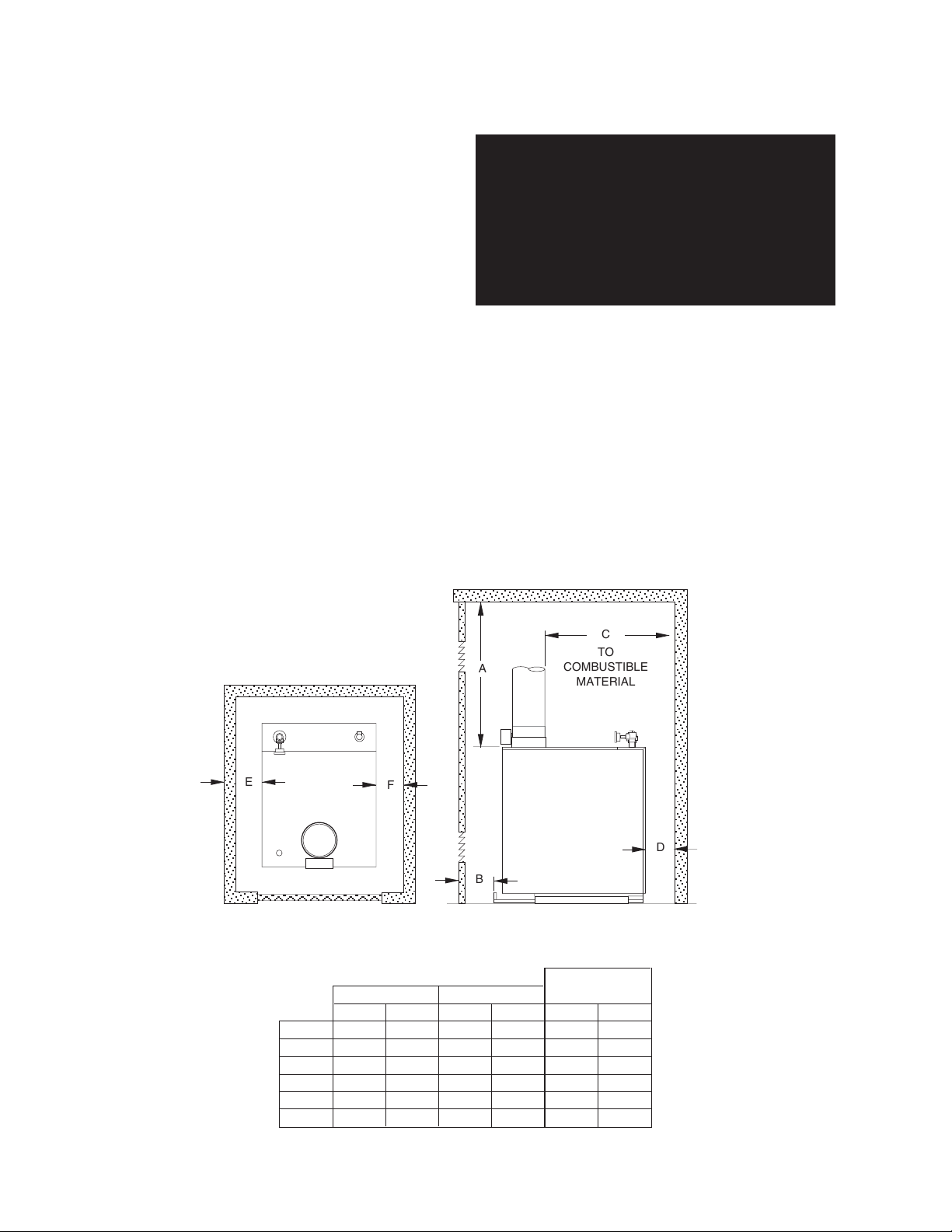
6. If the boiler is to be located in an alcove, closet or
other confined space the distances from the boiler
and it’s vent system to all combustible construction
must be equal to or greater than the minimum
clearances in Figure 1. When installed in a closet or
confined space two permanent openings of equal
area adjoining another room or rooms having
sufficient volume to meet the requirements of an
unconfined space must be provided. Each opening
must have a minimum free area of one square inch
per 1000 Btu/hr,
2200 mm2/kW
based on the total
input rating of all gas utilization equipment in the
confined area. Each opening must be no less than
2
100 in
,
64516 mm
must be within 12 in,
3 in,
76 mm
, from the top of the enclosure. The
bottom opening must be within 12 in,
2
, in size. The upper opening
305 mm
, of, but not less than
305 mm
but not less than 3 in, 76 mm, from the bottom of the
enclosure.
WARNING: Never install a PGB100W, propane
boiler in a closet or other confined or enclosed
spaceunless the installation conforms to the
latest revision of the National Fuel Gas Code,
ANSI Z223.1 and all applicable local building
codes! Failure to comply with this WARNING
could result in a fire or explosion causing
extensive property damage, severe personal
injury or death!
, of,
Figure 1: Clearances to Combustible Construction
NO FRONT WALL IN ALCOVE
*
E
F
FRONT
AL CL Servicing
in
A 24
B**2
C 6
D 4
E 7
F 4
AL = Alcove
CL = Closet
*No Front Wall in Alcove
mm
610
152
102
178
102
51
C
TO
A
B
in
6
4
7
4
mm
1295
51
152
102
178
102
COMBUSTIBLE
MATERIAL
For
in
N/A
N/A
10 254
10 254
mm
N/A
N/A
6
152
4 102
D
GB100W NATURAL OR PROPANE BOILER
INSTALLATION AND OPERATING INSTRUCTIONS
Page 5
COMBUSTIBLE FLOOR OPTION
The GB100W boiler has been designed for use on
noncombustible floors only. If a GB100W boiler is to
be installed on combustible flooring of any type, it MUST
be installed using the Special Base designed by the
Smith Cast Iron Boiler Co. Do NOT use any base other
than the one specifically designed for it if installing a
GB100W boiler on combustible flooring.
WARNING: Never install a GB100W boiler on
combustible flooring without using the special
base specifically designed for it by the Smith
Cast Iron Boiler Co. Do not alter in any way the
special base supplied by the Smith Cast Iron
Boiler Co. Failure to comply with this warning
may result in a fire causing property damage,
personal injury or death!
To order the Special Base contact the nearest
Smith Cast Iron Boiler distributor and ask for the
“Noncombustible Floor Pan”.
Determine where the boiler will be located by following
the instructions in the Boiler Location section of this
manual. Place the Special Base in this location and
fasten it in place to prevent it from moving while the
boiler is being placed on it.
If the GB100W is being installed in an alcove or closet
ensure that the minimum distance to combustible
construction requirements, listed in Figure 1, are met.
Figure 2: Special Base Installation on
Combustible Flooring
FRONT
GRILL
SUPPORT
CHANNEL
Remove the sheet metal base pan attached to the
boiler. Position the boiler in front of the Special Base. It’s
suggested that two lengths of 3" pipe the width of the
boiler, or longer, be placed under the boiler base side
panels.
CAUTION: Be careful not to damage the burners,
pilot assembly or any other gas train components
during this procedure. If a component is damaged,
replace it!
Carefully roll the boiler up to the front of the Special
Base. Align the boiler base side panels with the Special
Base support channels. Using great care, slide the boiler
onto the Special Base.
CAUTION: Never lift the boiler by the jacket panels
or flue collector/draft diverter or severe damage to
the boiler may result!
Center the boiler from side to side on the Special Base.
Ensure that the back of the burner base side panels
are flush with the back of the Special Base support
channels. Install the front grill supplied with the Special
Base. Complete the installation in accordance with the
instructions set forth in this manual.
COMBUSTION AIR
WARNING: This boiler must be supplied with
combustion air in accordance with Section 5.3,
Air for Combustion & Ventilation, of the latest
revision of the National Fuel Gas Code, ANSI
Z223.1/NFPA 54 and all applicable local building
codes. Failure to provide adequate combustion
air for this appliance can result in excessive
levels of carbon monoxide which can result in
severe personal injury or death!
Table 1: Vent and Chimney Dimensions
Boiler Size
(Sections)
Vent Pipe
Dia. (In.)
Chimney
Flue Size
Chimney
Height (Ft.)
3456789101112
5566778899
8 x 8 8 x 12
18 18 18 17 17 17 16 16 16 16

Page 6
GB100W NATURAL OR PROPANE BOILER
INSTALLATION AND OPERATING INSTRUCTIONS
To operate properly and safely this boiler requires a
continuous supply of air for combustion. Oxygen is used
by the burners in the boiler to burn the gas. In addition,
air is also used to assist in the safe disposal of the
products of combustion. This air is known as dilution
air and mixes with the products of combustion to assist
in it’s exit through the flue pipe and chimney. An
adequate supply of outside air must be available to
replace that used by these processes.
WARNING : If an appliance using any type of a
mechanical draft system operating under
positive pressure is connected to a chimney
flue, never connect any other appliances to this
flue. Doing so can result in the accumulation of
carbon monoxide which can cause severe
personal injury or death!
Older houses often have enough “leakage” to provide
an adequate amount of combustion air provided that
the demand for combustion air is not too great. Homes
that are relatively new or “tight” will most likely require
the installation of a fresh air duct or other means of
providing air for combustion. Any home utilizing other
gas burning appliances, a fireplace, wood stove or any
type of exhaust fan must be checked for adequate
combustion air when all of these devices are in operation
at one time. Sizing of an outside air duct must be done
to meet the requirements of all such devices.
Table 2: Combustion Air Duct Sizing
Input Btuh Input Btuh Input Btuh
Fresh Air 1/4" Wire Metal Wooden
Duct Size Mesh Screen Louvers Louvers
3" x 12" 144,000 108,000 36,000
8" x 8" 256,000 192,000 64,000
8" x 12" 384,000 288,000 96,000
8-1/2" x 16" 512,000 384,000 128,000
If the boiler will be located in an alcove, closet or any
confined space refer to item 6 in the Boiler Location
section of this manual.
CHIMNEY & VENT PIPE CONNECTIONS
WARNING: This boiler must be vented in
accordance with Part 7, Venting of Equipment, of
the latest revision of the National Fuel Gas code,
ANSI Z223.1/NFPA 54 and all applicable local
building codes. Improper venting of this
appliance can result in excessive levels of
carbon monoxide which can result in severe
personal injury or death!
Chimney Inspection & Sizing
If this boiler will be connected to a masonry chimney, a
thorough inspection of the chimney must be performed.
Ensure that the chimney is clean, properly constructed
and properly sized. Table 1 lists the flue size and
chimney height required for this boiler.
VENT CONNECTIONS
Always use a type B or C vent pipe of the proper
diameter for the boiler. Use the shortest, straightest
vent system possible for the particular application. The
vent system should be sloped up toward the chimney
at a rate of 1/4 in/ft,
is properly supported and each connection securely
fastened with at least 3 corrosion resistant sheet metal
screws. The termination of the vent pipe should be
flush with the inside of the chimney flue.
Always provide a minimum clearance of 6 in,
between type C vent pipe and any combustible
materials. Type B1 vent may be used, clearance
between it and any combustible material must be as
listed.
WARNING: Failure to maintain minimum
clearances between vent connectors and any
combustible material can result in extensive
property damage, severe personal injury or
death!
WARNING: Never modify or alter any part of the
draft hood or vent damper supplied with this
boiler. This includes the removal or alteration of
any baffles in the draft hood or flue collar.
Never install a vent pipe of a diameter different
than that of the boiler draft hood flue collar,
table 1. Failure to comply with this warning can
result in severe personal injury or death.
Common Vent Systems
If an existing appliance is removed from a common
venting system, the common venting system may then
be too large for the proper venting of the remaining
appliances connected to it. At the time of removal of
an existing boiler, the following steps shall be followed
with each appliance remaining connected to the
common venting system placed in operation, while the
other appliances remaining connected to the common
venting system are not in operation.
2 mm/m
. Ensure that the flue pipe
152 mm
,
When more than one appliance is connected to the
same chimney flue, the flue must be large enough to
handle both appliances.
The vent installation must be in accordance with Part 7
of the latest revision of the National Fuel Gas Code,
ANSI Z223.1/NFPA 54.
Au moment du retrait d'une chaudière existante, les
mesures suivantes doivent être prises pour chaque
appareil toujours raccordé au système d'évacuation
commun et qui fonctionne alors que d'autres appareils
toujours raccordés au système d'évacuation ne fonctionnent pas: système d'évacuation.

GB100W NATURAL OR PROPANE BOILER
INSTALLATION AND OPERATING INSTRUCTIONS
Page 7
a) Seal all unused openings in the common vent system
and repair any leaks.
Sceller toutes les ouvertures non utilisées du système d'évacuation.
b) Visually inspect the vent system to ensure that it is
properly pitched and sized and that there are no
structural deficiencies such as blockages, restrictions, leakage, or corrosion that could cause an
unsafe condition.
Inspecter de façon visuelle le système d'évacu-ation
pour déterminer la grosser et l'inclinaison horizontale
qui conviennent et s'assurer que le système est
exempt d'obstruction, d'étranglement de fruite, de
corrosion et autres défaillances qui pourraient
présenter des risques.
c) As far as is practical close all doors and windows
common to the space in which the vent system and
appliances connected to the common vent system
are contained. Turn on all exhaust fans, clothes
dryers, range hoods and appliances requiring air for
combustion that are not connected to the common
vent system. Ensure that all appliances operate at
maximum speed. Do not operate a summer exhaust
fan. Close all fireplace dampers.
Dans la mesure du possible, fermer toutes les portes
et les fenêtres du bâtiment et toutes les portes entre
l'espace où les appareils toujours raccordés du
système d'évacuation sont installés et les autres
espaces du bâtiment. Mettre en marche les
sécheuses, tous les appareils non raccordés au
système d'évacuation commun et tous les ventilateurs
d'extraction comme les hottes de cuisinère et les
ventilateurs des salles de bain. S'assurer que ces
ventilateurs fonctionnent à la vitesse maximale. Ne
pas faire fonctionner les ventilateurs d'été. Fermer
les registres des cheminées.
d) Place in operation the appliance being inspected.
Follow the lighting instructions. Adjust thermostat so
appliance will operate continuously.
Mettre l'appareil inspecté en marche. Suivre les
instructions d'allumage. Régler le thermostat de
façon que l'appareil fonctionne de façon continue.
f) After it has been determined that each appliance
remaining connected to the common venting system
properly vents when tested as outlined above, return
doors, windows, exhaust fans, fireplace dampers
and any other gas-burning appliance to their previous condition of use.
Une fois qu'il a été d éterminé, selon la métode
indiquée ci-dessus, que chaque appareil raccordé
au système d'évacuation est mis à l'air libre de façor
adéquate. Remettre les portes et les fenêtres, les
ventilateurs, les registres de cheminées et les
appareils au gaz à leur position originale.
g) Any improper operation of the common venting sys-
tem should be corrected so the installation conforms
with the National Fuel Gas Code, ANSI Z223.1/
NFPA 54. When resizing any portion of the common
venting system, the common venting system should
be resized to approach the minimum size as determined using the appropriate tables in Appendix F in
the National Fuel Gas Code, ANSI Z223.1/ NFPA 54
and or CSA B149 Installation Codes.
Tout mauvais fonctionnement du systéme d'évacution commun devrait étré corrigé de façor que
l'installation soit conforme au National Fue Gas
Code, ANSI Z223.1/NFPA 54 et (ou) aux codes d'installation CSA-B149. Si la grosseur d'une section du
système d' évacuation doit étré modifiée, le système
devrait étré modifié pour respecter les valeurs
minimales des tableaux pertinents de l'appendice F
du National Fuel Gas Code, ANSI Z223.1/ NFPA 54
et (ou) des codes d'installation CSA-B149.
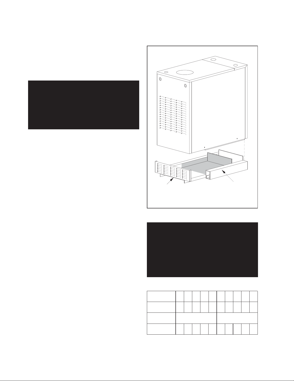
Vent Dampers
This boiler comes from the factory equipped with a
vent damper specifically engineered for it. The vent
damper must be properly installed to obtain the high
performance for which this boiler was designed. If the
damper is damaged or missing do not install the boiler
without it! Contact the nearest Smith Cast Iron Boilers
distributor to obtain the proper vent damper.
WARNING: On boilers with a constant pilot
ignition system, ensure that the hole in the
damper blade is not plugged. Failure to do this
could result in the spillage of carbon monoxide
which can result in severe personal injury!
e) Test for spillage at the draft hood relief opening after
5 minutes of main burner operation. Use the flame of
a match or candle, or smoke from a cigarette, cigar or
pipe.
Faire fonctionner le brûleur principal pendant 5 min
ensuite, déterminer si le coupe-tirage déborde à
l'ouverture de décharge. Utiliser la flamme d'une
allunette ou d'une chandelle ou la fumée d'une cigarette, d'un cigare ou d'une pipe.
Vent dampers are designed for use with only one
appliance. NEVER connect more than one appliance
to a single vent damper.
Locate the vent damper so that it is accessible and the
damper position indicator is visible. Maintain a minimum
of 6 inches between the damper and any combustible
materials!
Page 8
GB100W NATURAL OR PROPANE BOILER
INSTALLATION AND OPERATING INSTRUCTIONS
Fasten the vent damper to the flue collar and vent pipe
using at least 3 corrosion resistant sheet metal screws
per joint. Connect the damper harness to the top panel
with the BX connector supplied. Plug the Molex
connector on the damper harness into the mating plug
on the harness located inside the control compartment.
The vent damper is operating properly when it opens
completely upon a call for heat and closes completely
when the call for heat ends. The vent damper must be
in the open position when the boilers main burners are
in operation.
Figure 3: Vent Damper Location
DAMPER BLADE POSITIONED
FRONT TO BACK OF BOILER
MOTOR TO FACE
FRONT OF BOILER
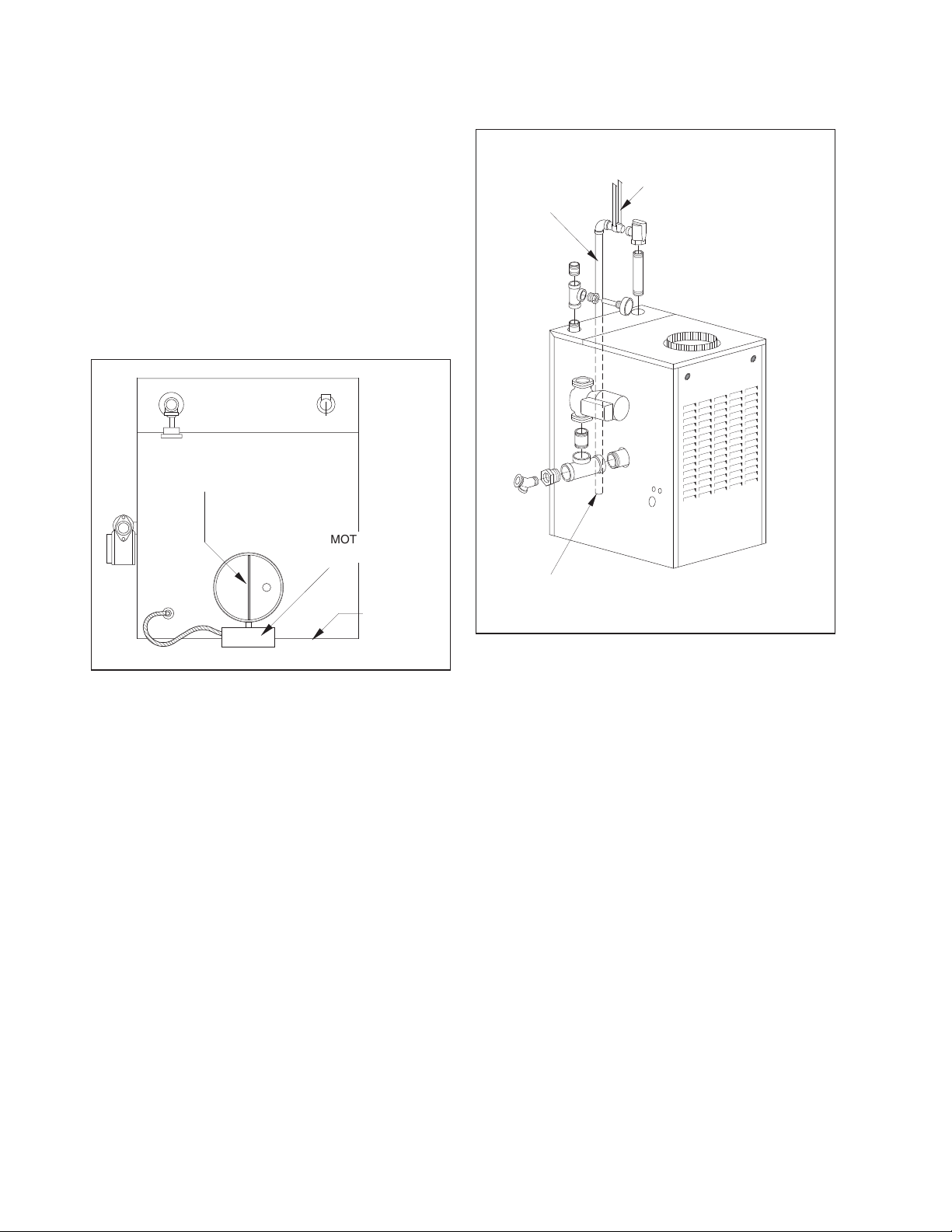
Figure 4: Heating System Piping
DISCHARGE PIPE
SIZE TO EQUAL
VALVE OUTLET.
DO NOT RESTRICT
FLOW.
SUPPORT DISCHARGE PIPING
SO AS TO AVOID STRAIN ON
THE VALVE BODY.
1" CLEARANCE MUST BE
FOR DISCHARGE
THROUGH ROOF
CONSULT THE
SMITH CO.
MAINTAINED BETWEEN
HOT WATER PIPING
AND COMBUSTIBLE
CONSTRUCTION.
FRONT OF
BOILER
HEATING SYSTEM PIPING
CAUTION: All piping must be installed by a qualified
technician in accordance with the provisions set
forth in the applicable ANSI/ASME standards and
local building codes and regulations. Improper
piping of this boiler can cause flooding, extensive
property damage, heating system damage or
damage to the boiler.
The GB100W hot water boiler comes from the factory
ready to be piped to the heating system. Each boiler is
equipped with a safety relief valve. This valve must be
piped in accordance with the ANSI/ASME Boiler and
Pressure Vessel Code, Section IV. Figure 4 provides a
pictorial description of the boiler and piping components.
DISCHARGE SO AS TO AVOID EXPOSURE OF PERSONS TO
HOT LIQUID OR VAPOR. L EAVE O PEN EN D VISIBLE FOR
PERI ODIC INSPECTION FOR SLOW LEAKAGE OR DRIPS.
GB100W NATURAL OR PROPANE BOILER
INSTALLATION AND OPERATING INSTRUCTIONS
Page 9
The boiler should be placed in the location selected for
it. Refer to the BOILER LOCATION section in this
manual. Ensure that the boiler is level from front to
back and from side to side. Use metal shims to level
the boiler. NEVER use wood, plastic or other
combustible materials as shims.
All heating system piping must be installed in
accordance with the ANSI/ASME Boiler and Pressure
Vessel Code, Section IV, and ANSI/ ASME CSD-1,
Standard for Controls and Safety Devices for
Automatically Fired Boilers. All applicable local codes
and ordinances must also be followed.
If the boiler is installed above any radiation elements it
must be fitted with a low water cutoff device, L.W.C.O.,
installed above the normal boiler water level.
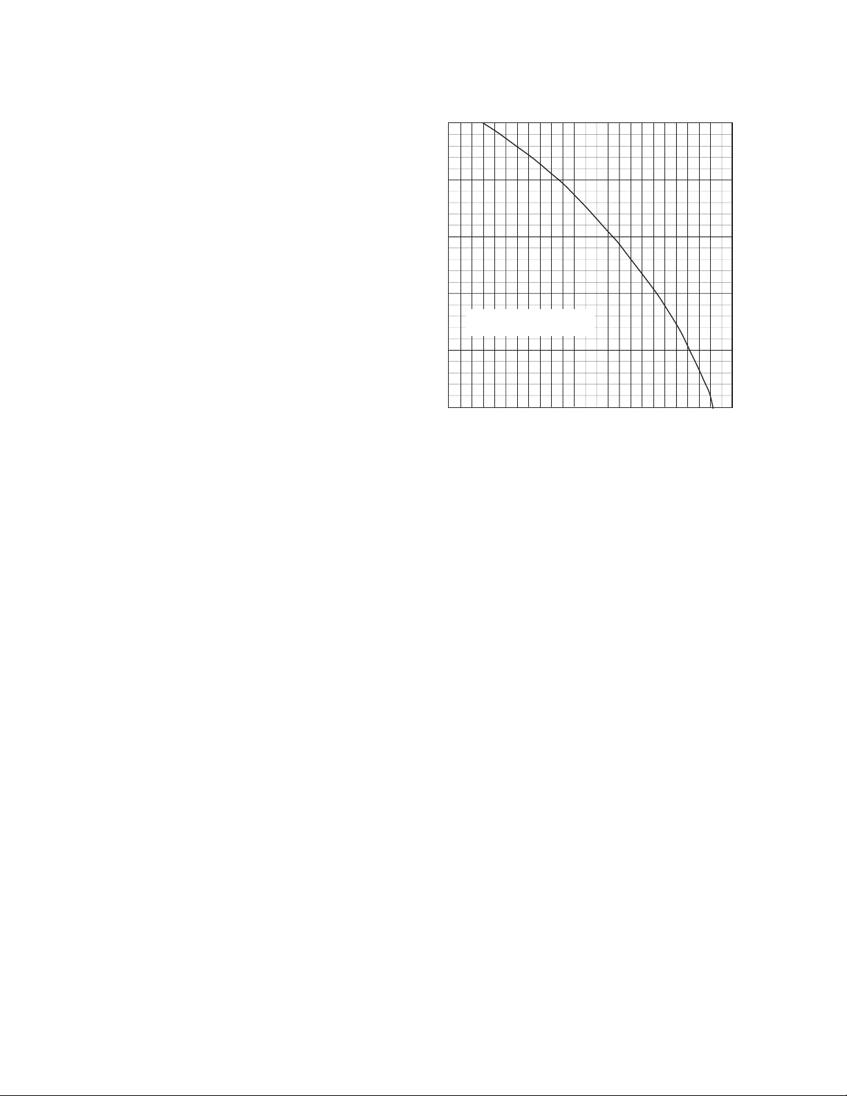
Circulators
A TACO 007 circulator has been supplied as standard
equipment with the boiler. The 007 is sized for use in a
closed heating system with a 30 psi,
207 kPa
, maximum
operating pressure. If the 007 circulator furnished with
this boiler does not have the required capacity for the
system in which it is to be installed, an extra zone
circulator must be provided. A circulator with a higher
capacity may also be used. Figure 5 depicts the
performance curve for the TACO 007 circulator.
Figure 5: TACO 007 Performance Curve
10
8
6
4
HEAD - FEET OF WATER
TACO 007 CIRCULATOR
PERFORMANCE CURVE
2
0
0 5 10 15 20 25
FLOW - GPM
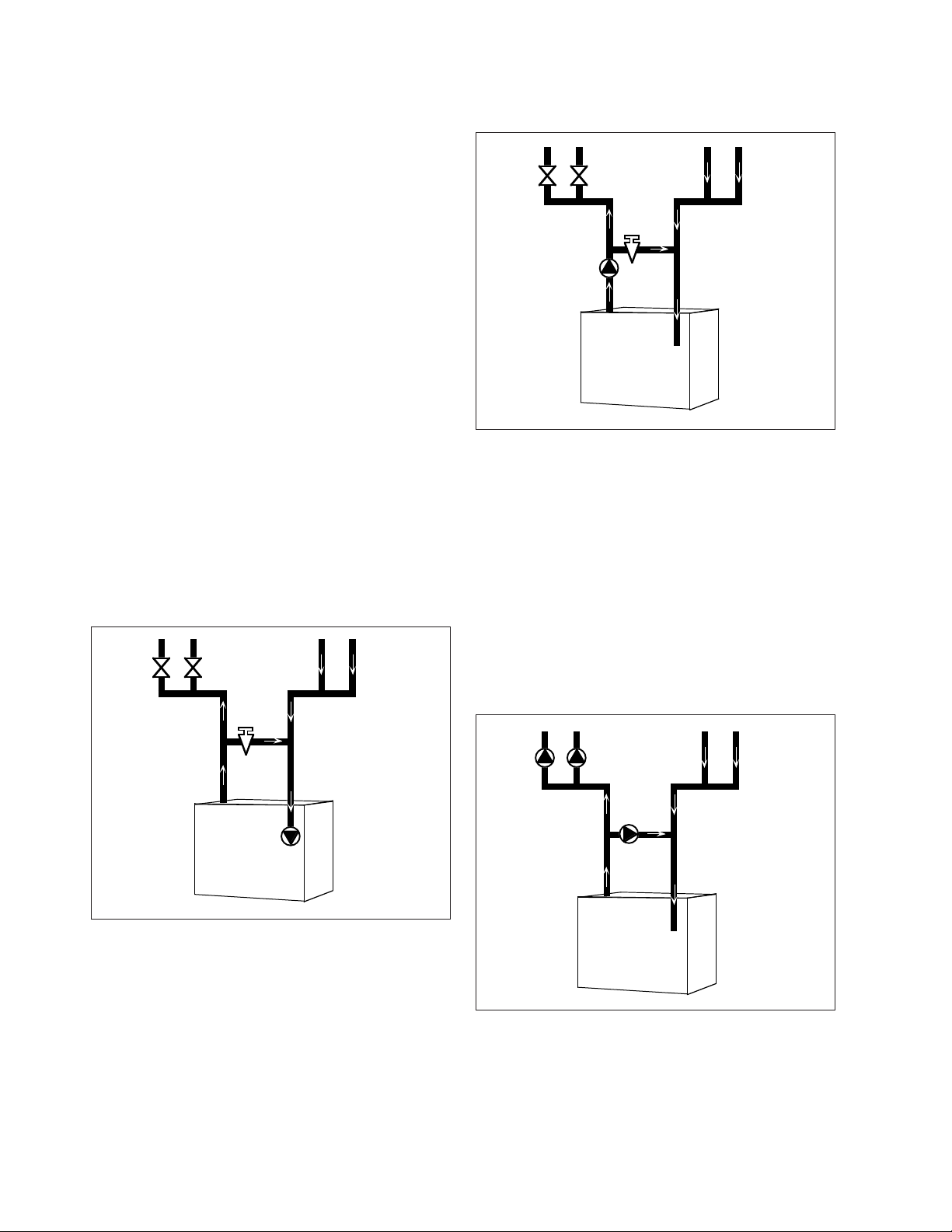
Piping For Use With Cooling Units
The boiler, when used in connection with a refrigeration
system, must be installed so the chilled medium is piped
in parallel with the boiler. Appropriate valves must be
used to prevent the chilled water from entering the
boiler. See Figure 6 for the proper piping layout.
When a boiler is connected to a heating coil that may
be exposed to refrigerated air from an air handling
device, the piping system must be equipped with flowcontrol valves or some other automatic means of
preventing gravity circulation of the boiler water during
the cooling cycle.
Page 10
GB100W NATURAL OR PROPANE BOILER
INSTALLATION AND OPERATING INSTRUCTIONS
CAUTION: To prevent damage due to excessive
condensation, one of the following piping options
should be used.
System Bypass
For systems using a circulator on the return as either a
single zone, or multiple zones with zone valves, install
a system bypass line between the supply and return
on the suction side of the circulator, see Figure 7.
Install a metering valve in this bypass line to regulate
the amount of flow that will be diverted to the return. A
plug valve offers the best control for this application.
Although other valves may be less expensive, a plug
valve will be easier to set accurately.
In the absence of a flow indicator, set the metering
valve using temperature as a guide. The accompanying
diagram suggests one scenario. This addition requires
only two tees, a plug valve, and a small amount of pipe
and offers the simplest approach to reliably control
condensation. For this system and those that follow,
be aware that you are using a percentage of the pump
capacity to blend, but the friction loss for the entire
pump flow has been reduced. In most cases, the
standard pump packaged with the boiler has enough
capacity to feed the baseboard distribution system and
the bypass line.
Figure 8: Pump Away Bypass
SUPPLY
50%
160° F
100%
160° F
PUMP AWAY
BYPASS
50%
160° F
RETURN
50%
120° F
100%
140° F
Pumped Blend
An additional circulator can also be used to provide a
return water temperature blend. This method works
well with systems with multiple zones with circulators,
see Figure 9. The dedicated bypass circulator provides
a strong blending flow without diminishing the flow
available to any heating zone. Any residentially sized
circulator is adequate for this purpose.
Figure 7: System Bypass
50%
160° F
100%
160° F
SUPPLY
SYSTEM
BYPASS
50%
160° F
RETURN
50%
120° F
100%
140° F
Pump Away Bypass
For systems that use a single circulator to pump away
from the boiler, the bypass should be installed on the
discharge side of the circulator, see Figure 8. Full
temperature water supplies the baseboard distribution
system as before. Half of the circulator’s volume moves
through the bypass, blending and heating the cooler
return water. Again, the cost of installing the bypass is
small and setting it by temperature can be accomplished
with a contact thermometer.
Each of these bypass solutions also has the added
benefit of increasing circulation in the boiler which will
maximize tankless coil output and increase the accuracy
of temperature sensing controls.
Figure 9: Pumped Bypass
100%
160° F
200%
160° F
SUPPLY
PUMPED
BYPASS
100%
160° F
RETURN
100%
120° F
200%
140° F
 Loading...