

Smith Cast Iron Boilers 28A User Manual
MEA#273-89-E
SERIES 28A
GAS OR OIL BOILER
INSTALLATION & OPERATING
INSTRUCTIONS
28A-IOM-7
DESIGNED AND TESTED ACCORDING TO A.S.M.E. BOILER AND PRESSURE
VESSEL CODE, SECTION IV FOR A MAXIMUM ALLOWABLE WORKING PRESSURE
OF: 15 PSI STEAM OR 80 PSI WATER.
TO INSTALLER
READ THESE INSTRUCTIONS CAREFULLY. THEY WILL
SAVE YOU VALUABLE TIME WHEN ASSEMBLING THE BOILER.
WARNING: If the information in this manual is not followed exactly, a fire or explosion
may result causing property damage, personal injury or loss of life.
Do not store or use gasoline or other flammable vapors and liquids in the vicinity of
this or any other appliance.
WHAT TO DO IF YOU SMELL GAS:
• Do not try to light any appliance.
• Do not touch any electrical switch. Do not use any phone in your building.
• Immediately call your gas supplier from a neighbor’s phone. Follow the gas
supplier’s instructions.
• If you cannot reach your gas supplier, call the fire department.
Installation and service must be performed by a qualified installer, service agency or
the gas supplier.
INSTALLER, THESE INSTRUCTIONS T O BE AFFIXED ADJACENT TO THE BOILER.
CONSUMER, RETAIN THESE INSTRUCTIONS FOR FUTURE REFERENCE PURPOSES.
FOR JACKET ASSEMBLY AND BURNER SET UP SEE SEPARATE INSTRUCTIONS.
WESTCAST, INC.
260 NORTH ELM STREET WESTFIELD, MA 01085
TEL. (413) 562-9631 FAX (413) 562-3799
In Canada: 5211 Creekbank Road, Mississauga, Ont. L4W 1R3 (905) 625-2991 Fax (905) 625-6610

Page 2
SERIES 28A BOILER INSTALLATION AND OPERATION INSTRUCTIONS
CONTENTS
Before You Start .................................................page 2
Boiler Ratings & Capacities................................page 2
Boiler Location ...................................................page 2
Combustion Air & Ventilation..............................page 3
Chimney & Vent Pipe Connections ....................page 4
Common V ent Systems......................................page 6
Boiler Assembly ................................................ page 7
General Piping Requirements ..........................page 14
Water Boiler Piping ..........................................page 15
Steam Boiler Piping..........................................page 18
Burner Installation ............................................page 21
Electrical Wiring ...............................................page 22
Boiler Operation .............................................. page 22
Boiler Checking & Adjustment..........................page 23
Boiler Maintenance ..........................................page 23
Repair Parts .....................................................page 25
Health Warnings.......................................... back cover
BEFORE YOU START
This manual covers the assemb ly, installation, operation
and maintenance of a Series 28A low pressure steam
or hot water boiler.
The 28A Series boilers are supplied completely knocked
down for field assembly, knocked down but with an
assembled block or as complete factory assembled
packaged boilers. All boiler components should be
inspected for damage upon receipt. Any damage should
be immediately reported to the trucker or wholesaler. All
boiler components should be stored in a clean dry area.
To obtain the safe, dependable, efficient operation and
long life for which this boiler was designed, these
instructions must be read, understood and followed.
The Series 28A boilers have been design certified by
CSA. Each unit has been constructed and hydrostatically tested for a maximum working pressure of 15
psi for steam, 80 psi for water, in accordance
with Section IV of the A.S.M.E. Boiler and Pressure
Vessel Code for cast iron boilers.
All aspects of the boiler installation must conform to the
requirements of the authority having jurisdiction, or, in
the absence of such requirements, to the National Fuel
Gas Code, ANSI Z223.1/NFPA 54-latest revision or to
the Installation of Oil Burning Equipment, ANSI/NFPA
31.
Where required by the authority having jurisdiction, the
installation must conform to the Standard for Controls
and Safety Devices for Automatically Fired Boilers,
ANSI/ASME CSD-1.
In Canada, the installation must be in accordance with
the requirements of CAN/CGA B149.1 or .2, Installation
Code for Gas Burning Appliances and Equipment.
In the Commonwealth of Massachusetts the installation
of a gas burner must be performed by a licensed
plumber or gas fitter.
The owner should maintain a record of all service work
performed with the date and a description of the work
done. Include the name of the ser vice organization for
future reference.
Direct all questions to your Smith Cast Iron Boiler
distributor or contact the Smith Customer Service
Department. Always include the model and serial
numbers from the rating plate of the boiler in question.
BOILER RATINGS & CAPACITIES
Before undertaking the installation of the 28A Series
boiler check the boiler rating plate to ensure that the
boiler has been sized properly for the job. The “Net
I=B=R Ratings” specify the equivalent amount of direct
cast iron radiation that the boiler can supply under
normal conditions. Also ensure that the boiler has been
set up for the type of fuel available at the installation
site.
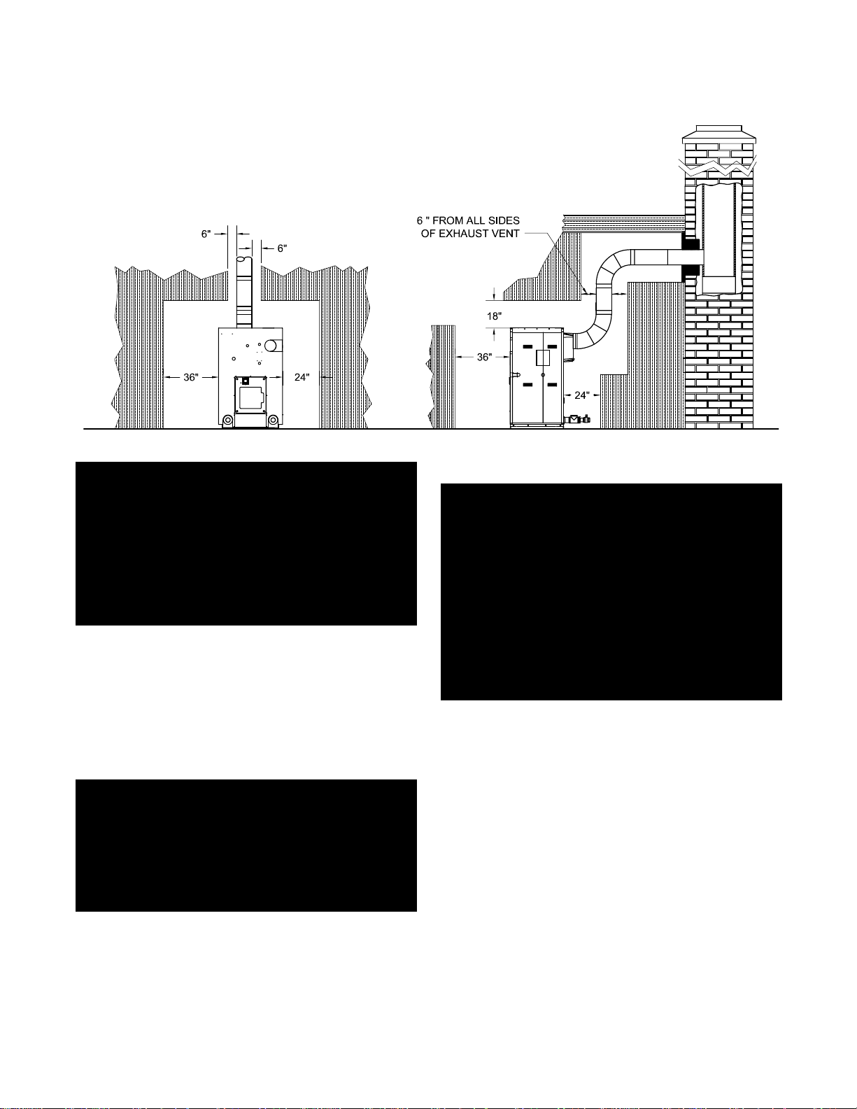
BOILER LOCATION
1. Locate the boiler in an area that provides good
access to the unit. A minimum distance of 6 in,
0.15m
must be maintained between the boiler
and combustible construction. Servicing may
require the removal of jacket panels so service
clearances should be maintained. Allow a minimum
clearance of 3 ft,
construction and the left side, front and smoke hood.
A minimum clearance of 2 ft,
maintained between adjacent construction and the
right side and back of the boiler. Accessibility
clearances should take precedence over minimum
clearances to combustible construction, Figure 1.
2. An optimum site will be level, central to the piping
system, close to a chimney and have adequate
fresh air for combustion.
3. The boiler should be installed on a level, flat,
concrete floor or pad that is structurally sound and
will support the weight of the boiler. If a concrete
pad is used it must be at least 2" thick. Never install
the boiler on a concrete floor or pad that contains
wires, cables, water pipes or hoses. This boiler is
designed for non-combustible floors!
0.9 m
between adjacent
0.6 m
should be
SERIES 28A BOILER INSTALLATION AND OPERATION INSTRUCTIONS
Figure 1- Service Clearances to Adjacent Construction
Page 3
WARNING: Never install a 28A boiler on top of
combustible flooring without consulting the
local building authorities for proper installation
guidelines! A minimum clearance of 6 in,
0.15 m
and combustible construction. F ailure to comply
with this warning may result in a fire causing
extensive property damage, severe personal
injury or death!
4. DO NOT install this boiler in a location that would
5. DO NOT place this boiler in a location that would
WARNING: Never store combustible materials,
gasoline or any product containing flammable
vapors or liquids in the vicinity of the boiler.
Failure to comply with this warning can result
in an explosion or fire causing extensive
property damage, severe personal injury or
death!
must be maintained between the boiler
subject any of the electrical components to direct
contact with water or excessive moisture during
operation or servicing.
restrict the introduction of combustion air into the
boiler.
COMBUSTION AIR & VENTILATION
WARNING: This boiler must be supplied with
combustion and ventilation air in accordance
with Section 5.3, Air for Combustion &
Ventilation, of the latest revision of the National
Fuel Gas Code, ANSI Z223.1/NFPA 54 and all
applicable local building codes. Canadian
installations must comply with CAN/CGA B149.1
or .2 Installation Code. Failure to provide
adequate combustion air for this boiler can
result in excessive levels of carbon monoxide
which can result in severe personal injury or
death!
To operate properly and safely this boiler requires a
continuous supply of air for combustion. An adequate
supply of air must be available to replace the air used
by the combustion process. NEVER store objects on or
around the boiler.
CAUTION: Never use an exhaust fan in the boiler
room. The boiler room must never be under a
negative pressure or improper burner operation will
occur!
NOTE: Forced make-up air supplied to the boiler
room must be approved by the local authorities. A
minimum of 30 ft3/GAL,
20 ft3/100 MBH (Therm),
be provided.
0.22 m3/L
0.024 m3/kW
for oil or
for gas must

Page 4
SERIES 28A BOILER INSTALLATION AND OPERATION INSTRUCTIONS
All Air From Inside The Building
If the boiler is to be located in a confined space minimum clearances of 24 in,
between the boiler and any adjacent construction. When
installed in a confined space, two permanent openings
communicating with an additional room(s) are required.
The combined volume of these spaces must have
sufficient volume to meet the criteria for an unconfined
space. The total air requirements of all fuel burning
equipment or any type of exhaust fan must be
considered when making this determination.
Each opening must have a minimum free area of 1 in2/
1000 Btu/hr, 140 in2/GPH,
total input rating of ALL fuel burning equipment in the
confined area. Each opening must be no less than 100
in2,
64,516 mm
within 12 in,
from, the top of the enclosure.
The bottom opening must be within 12 in,
but not less than 3 in,
enclosure.
All Air From Outside The Building
When installed in a confined space Two permanent
openings communicating directly with, or by ducts to,
the outdoors or spaces that freely communicate with the
outdoors must be present. The upper opening must be
within 12 in,
from, the top of the enclosure. The bottom opening must
be within 12 in, 305 mm of, but not less than 3 in,
76 mm
Where directly communicating with the outdoors or
communicating with the outdoors through vertical ducts,
each opening shall have a minimum free area of 1 in2/
4000 Btu/hr, 35 in2/GPH,
rating of all of the equipment in the enclosure.
Where communicating with the outdoors through
horizontal ducts, each opening shall have a minimum
free area of 1 in2/2000 Btu/hr, 70 in2/GPH,
kW
the enclosure. When ducts are used, they must have the
same cross-sectional area as the free area of the
opening to which they connect. When calculating the
free area necessary to meet the make-up air
requirements of the enclosure, consideration must be
given to the blockage effects of louvers, grills and
screens. Screens must have a minimum mesh size of
1/4 in,
is not known the louver or grill should be sized per Table 1.
from, the bottom of the enclosure.
of the total input rating of all of the equipment in
6.4mm
2
in size. The upper opening must be
305 mm
305 mm
. If the free area through a louver or grill
610 mm
2200 mm2/kW
of, but not less than 3 in,
must be maintained
based on the
305 mm
76 mm
of, but not less than 3 in,
from, the bottom of the
550 mm2/kW
of the total input
1100 mm2/
76 mm
of,
76 mm
Table 1- Make-up Air Louver Sizing
Required Cross Sectional Area (in2)
Metal Wooden
Input 1/4" Wire Louvers Louvers
(MBH) Screen 75% Free Area 25% Free Area
1000 250 333 1000
1200 300 400 1200
1400 350 467 1400
1600 400 533 1600
1800 450 600 1800
2000 500 667 2000
2200 550 733 2200
2400 600 800 2400
2600 650 867 2600
2800 700 934 2800
3000 750 1000 3000
3200 800 1066 3200
3400 850 1134 3400
3600 900 1200 3600
3800 950 1267 3800
4000 1000 1334 4000
4200 1050 1400 4200
4400 1100 1467 4400
4600 1150 1533 4600
4800 1200 1600 4800
CHIMNEY & VENT PIPE
CONNECTIONS
WARNING: The vent installation must be in
accordance with Part 7, Venting of Equipment,
of the National Fuel Gas Code, ANSI Z223.1/
NFPA 54-latest revision, the ASHRAE Equipment
Handbook on Venting or applicable provisions
of the local building codes. Canadian
installations must comply with CAN/CGA B149.1
or .2 Installation Code. Improper venting of this
boiler can result in excessive levels of carbon
monoxide which can result in severe personal
injury or death!
CAUTION: The products of combustion from a 28A
must be safely vented to the outdoors while
ensuring that the flue gasses do not cool
prematurely. It’s critical that the chimney system be
properly designed to handle the flue gases. An
oversized or uninsulated chimney can cause the
moisture in the flue gases to condense resulting in
damage to the chimney system unless it’s
specifically designed for condensate. If this is the
case a suitable condensate drain must be used to
protect the boiler from condensate.
NOTE: Our warranty does not cover corrosion
damage to the boiler or its vent system caused by
flue gas condensate!
SERIES 28A BOILER INSTALLATION AND OPERATION INSTRUCTIONS
Page 5
Chimney Inspection & Sizing
If this boiler will be connected to a masonry chimney, a
thorough inspection of the chimney must be performed.
Ensure that the chimney is clean, properly constructed,
lined and properly sized, see Figure 2. Table 2 lists the
equivalent breeching and flue sizes required for the 28A
boilers.
Table 2 - Equivalent Breeching & Chimney Size
Boiler Model Breeching Size Chimney Size
in
28A-4 10
28A-5 10
28A-6 10
28A-7 12
28A-8 12
28A-9 14
28A-10 14
28A-11 14
28A-12 14
28A-13 14
28A-14 16
28A-15 16
28A-16 16
28A-17 18
28A-18 18
mm
254
254
254
305
305
356
356
356
356
356
406
406
406
406
457
in
10
10
10
12
12
14
14
14
14
14
16
16
16
18
18
mm
254
254
254
305
305
356
356
356
356
356
406
406
406
406
457
Note: These sizes are based on a 20 foot chimney height.
The 28A is designed for pressurized operation with a
back pressure of 0.10 in,
smoke hood slide damper. If the vent configuration
results in a back pressure greater than this, the burner
capacity may have to be verified. Contact the Smith
Technical Service Department to verify the burner
capacity.
The chimney must be able to provide 0.10" WC at the
boiler outlet. If the chimney is 50 ft. or taller it may
produce excessive draft (approx. - 0.25" WC) and a
barometric draft regulator may be needed.
When more than one appliance is connected to the
same chimney flue the flue must be large enough to
safely vent the combined output of all the appliances.
WARNING: If an appliance using any type of
a mechanical draft system operating under
positive pressure is connected to a chimney
flue, never connect a Category I appliance to
this flue. Doing so can result in the
accumulation of carbon monoxide which can
cause severe personal injury or death!
2.54 mm
W.C. before the
Figure 2 - Vertical Venting

Page 6
SERIES 28A BOILER INSTALLATION AND OPERATION INSTRUCTIONS
VENT CONNECTIONS
WARNING: Never modify or alter any part of the
boiler’s smoke hood. This includes the removal
or alteration of any baffles. Never install a vent
pipe of a diameter different than that of the
boiler smoke hood outlet. Failure to comply with
this warning can result in severe personal injury
or death.
Locate the boiler as close to the chimney as possible.
Use the shortest, straightest vent connector possible for
the installation. If horizontal runs exceed 5 ft,
must be supported at 3 ft,
hangers. Use a single wall stainless or single wall
galvanized steel vent pipe the same diameter as the flue
collar to connect the boiler to a masonry chimney. When
using an approved metal chimney system use the
appropriate vent connector. The vent connector should
be sloped up toward the chimney at a minimum rate of
1/4 in/ft,
must terminate flush with the inside of the chimney flue.
Fasten each single wall vent connection with at least 3
corrosion resistant sheet metal screws.
The vent materials used in positive pressure vent
systems must be certified to UL 1738 for installations
in the United States, ULS636 for installations in Canada.
The following manufactures have systems that meet
these requirements:
Heat-Fab, Inc.
38 Hayward Street
Greenfield, MA 01301, (800) 772-0739.
Z-Flex U.S., Inc.
20 Commerce Park
North, Bedford, NH 03110-6911, (800) 654-5600.
Protech Systems Inc.
26 Gansevoort Street,
Albany, NY 12202 (518) 463-7284
2 cm/m
. On masonry chimneys the connector
0.9 m
intervals with overhead
1.5 m
they
WARNING: Failure to maintain minimum
clearances between vent connectors and any
combustible material can result in a fire causing
extensive property damage, severe personal
injury or death!
COMMON VENT SYSTEMS
If an existing boiler is removed from a common venting
system, the common venting system may then be too
large for the proper venting of the remaining appliances
connected to it. At the time of removal of an existing
boiler, the following steps shall be followed with each
appliance remaining connected to the common venting
system placed in operation, while the other appliances
remaining connected to the common venting system are
not in operation.
Au moment du retrait d'une chaudière existante, les
mesures suivantes doivent être prises pour chaque
appareil toujours raccordé au système d'évacuation
commun et qui fonctionne alors que d'autres appareils
toujours raccordés au système d'évacuation ne
fonctionnent pas: système d'évacuation
a) Seal any unused openings in the common venting
system.
Sceller toutes les ouvertures non utilisées du
système d'évacuation.
b) Visually inspect the venting system for proper size
and horizontal pitch and determine there is no
blockage or restriction, leakage, corrosion and other
deficiencies which could cause an unsafe condition.
Inspecter de façon visuelle le système d'évacuation
pour déterminer la grosser et l'inclinaison
horizontale qui conviennent et s'assurer que le
système est exempt d'obstruction, d'étranglement
de fruite, de corrosion et autres défaillances qui
pourraient présenter des risques.
WARNING: Breeching under positive pressure
must be certified to UL 1738 for installations in
the United States, ULS636 for installations in
Canada. Type B1 vent SHALL NOT be used.
Failure to comply with this warning can result
in severe personal injury or death.
Always provide a minimum clearance of 6 inches
between single wall metal vent pipe and all combustible
materials.

SERIES 28A BOILER INSTALLATION AND OPERATION INSTRUCTIONS
Page 7
c) Insofar as is practical, close all building doors and
windows and all doors between the space in which
the appliances remaining connected to the common
venting system are located and other spaces of the
building. Turn on clothes dryers and any appliance
not connected to the common venting system. Turn
on any exhaust fans, such as range hoods and
bathroom exhaust, so they will operate at maximum
speed. Do not operate a summer exhaust fan for a
boiler installation. Close fireplace dampers.
Dans la mesure du possible, fermer toutes les
portes et les fenêtres du bâtiment et toutes les
portes entre l'espace où les appareils toujours
raccordés du système d'évacuation sont installés et
les autres espaces du bâtiment. Mettre en marche
les sécheuses, tous les appareils non raccordés au
système d'évacuation commun et tous les
ventilateurs d'extraction comme les hottes de
cuisinère et les ventilateurs des salles de bain.
S'assurer que ces ventilateurs fonctionnent à la
vitesse maximale. Ne pas faire fonctionner les
ventilateurs d'été. Fermer les registres des
cheminées.
d) Place in operation the appliance being inspected.
Follow the lighting instructions. Adjust thermostat so
appliance will operate continuously.
Mettre l'appareil inspecté en marche. Suivre les
instructions d'allumage. Régler le thermostat de
façon que l'appareil fonctionne de façon continue.
e) Test f or spillage at the draft hood relief opening after
5 minutes of main burner operation. Use the flame
of a match or candle, or smoke from a cigarette,
cigar or pipe.
Faire fonctionner le brûleur principal pendant 5 min
ensuite, déterminer si le coupetirage déborde à
l'ouverture de décharge. Utiliser la flamme d'une
allunette ou d'une chandelle ou la fumée d'une
cigarette, d'un cigare ou d'une pipe.
f) After it has been determined that each appliance
remaining connected to the common venting
system properly vents when tested as outlined
above, return doors, windows, exhaust fans,
fireplace dampers and any other gas-burning
appliance to their previous condition of use.
g) Any improper operation of the venting system
should be corrected so the installation conforms with
the National Fuel Gas Code, ANSI Z223.1/NFPA 54.
When resizing any portion of the common venting
system, the common venting system should be
resized to approach the minimum size as
determined using the appropriate tables in
Appendix F in the National Fuel Gas Code, ANSI
Z223.1/NFPA 54 and or CSA B149 Installation
Codes.
Tout mauvais fonctionnement du systéme
d'évacution commun devrait étré corrigé de façor
que l'installation soit conforme au National Fue Gas
Code, ANSI Z223.1/NFPA 54 et (ou) aux codes
d'installation CAN/CGA-B149. Si la grosseur d'une
section du système d' évacuation doit étré modifiée,
le système devrait étré modifié pour respecter les
valeurs minimales des tableaux pertinents de
l'appendice F du National Fuel Gas Code, ANSI
Z223.1/NFPA 54 et (ou) des codes d'installation
CSA-B149.
BOILER ASSEMBLY
Locate the boiler installation site based on the guidelines set forth in the BOILER LOCATION section.
WARNING: Never install a 28A boiler on top of
combustible flooring without consulting the
local building authorities for proper installation
guidelines! Failure to comply with this warning
can result in a fire causing extensive property
damage, severe personal injury or death!
Packaged Boilers/Factory Assembled Sections
A careful inspection of all assemblies should be made
to detect possible shipping damage. Packaged boilers
and factory assembled blocks of sections are
hydrostatically tested at the factory to insure pressure
tightness. A hydrostatic retest should be performed
before any piping connections are made to detect leaks
caused by shipping.
NOTE: All assembled boiler sections shall pass the
hydrostatic tests prescribed in Section IV of the
ASME Boiler and Pressure Vessel Code.
CAUTION: Do not connect any boiler controls during
the pressure test or they will be damaged!
Une fois qu'il a été d éterminé, selon la métode
indiquée cidessus, que chaque appareil raccordé
au système d'évacuation est mis à l'air libre de façor
adéquate. Remettre les por tes et les fenêtres, les
ventilateurs, les registres de cheminées et les
appareils au gaz à leur position originale.

Page 8
SERIES 28A BOILER INSTALLATION AND OPERATION INSTRUCTIONS
Completed boilers must be tested as follows:
Steam Boilers – the assembled boiler sections shall be
subjected to a hydrostatic test pressure of not less than
45 psig,
Water Boilers – the assembled boiler sections shall be
subjected to a hydrostatic test pressure of not less than
1 1/2 times the maximum allowable working pressure.
The hydrostatic pressure shall not exceed the required
test pressure by more than 10 psig,
test.
WARNING: Never leak test the boiler using
compressed air! Failure to comply with this
warning may result in property damage, severe
personal injury or death!
1. Plug all openings in the boiler and fill it with water.
2. Bleed any air off through one of the top tappings
3. Maintain the test pressure while carefully checking
NOTE: The shipping lugs, lifting lugs and metal
banding should be removed before installing the
jacket on factory assembled sections.
CAUTION: Remove the left jacket panels on fully
packaged boilers and ensure that the cleanout
covers are secure and gas tight. Loose covers could
damage the boiler.
315 kPa
then increase the pressure as outlined above.
for leaks. If a leak is found it must be eliminated,
see Table 4 and supporting text. Once the
assembled boiler sections pass the hydrostatic test
drain them and remove the plugs from any tappings
that will be used in service.
.
70 kPa
during the
2. Carefully place the back section in position on the
angles as shown in Figure 4.
WARNING: The section MUST be fully supported
to prevent it from falling! Failure to comply with
this warning may result property damage,
severe personal injury or death!
Figure 4 - Section Placement
3. Clean the hydronic port connector sealing surfaces
and the rope grooves with a wire brush to remove
any rust or debris.
4. Apply two coats of the spray adhesive supplied with
the boiler to the rope groove. Allow time for the first
coat to dry before applying the second coat. When
the second coat is tacky press the rope into the rope
groove. Trim the rope off leaving 1/8 in.,
extending beyond the surface of the cast iron
section, Figure 5.
Figure 5 - Rope Installation
3.2 mm
Assembly of Knocked-Down Boilers
Drilled and tapped steel angles are furnished to provide
a level footing, ease of section assembly and a point of
jacket attachment.
1. Set the angles as shown in Figure 3. They must be
parallel and level. Grout under the angles to provide
a continuous bearing surface.
Figure 3 - Steel Angle Placement
SERIES 28A BOILER INSTALLATION AND OPERATION INSTRUCTIONS
Page 9
5. Insert the large port connector with its steel inner
ring into the upper port.
6. Insert the two round por t connectors into the lower
ports.
NOTE: Apply the spray adhesive supplied with the
boiler to the port recess to hold the port connector
in place if necessary.
7. Select the correct intermediate section and carefully
move it into place against the back section, Figure
4.
CAUTION: Any steam uptake and heater sections
must be located as shown in Table 3. Failure to
comply with this caution may result in poor boiler
performance and prevent the jacket from fitting!
Only one intermediate section with an external leg
boss has been included. It should be located toward
the front of the boiler for optional low water cutoff
use. See Table 3.
NOTE: A putty knife or similar tool can be used to
hold the port connectors in place while the
intermediate section is positioned. It must be
removed before the sections make contact or the
port connector will be damaged resulting in a leak!
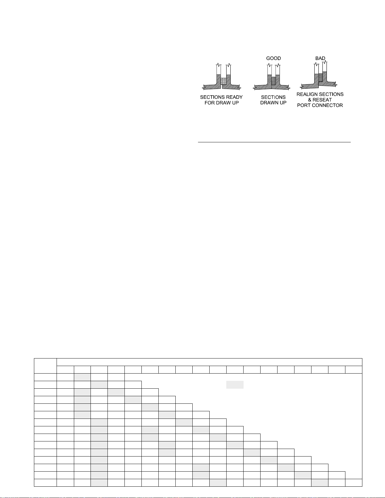
8. Insert the four draw rods through the casting
bosses. Thread nuts onto one end of the rods. Place
washers on the other end of the rods before
threading nuts onto them. Sn ug the nuts finger tight.
Use a spirit level to ensure that the first two sections
are plumb and properly aligned, Figure 6. Check the
rope to insure that it’s properly positioned. Once the
sections are plumb and the rope and port
connectors are properly positioned follow the torque
sequence shown in Table 4.
Figure 6 - Section Alignment
Table 4 - Section Torque Sequence
Step Rod Position Torque
ft lbs
1 Upper Right 25
2 Lower Left 25
3 Lower Right 25
4 Upper Left 10
5 Upper Right 50
6 Lower Left 50
7 Lower Right 50
8 Upper Right 75
9 Lower Left 75
10 Lower Right 75
11 Upper Left 30
12 Upper Right 125
13 Lower Left 125
14 Lower Right 125
15 Upper Right 125
16 Upper Left 40
Nm
34
34
34
14
68
68
68
102
102
102
42
169
169
169
169
54
NOTE: With these initial torques the sections may
not be metal to metal, which is acceptable. If any of
the ports leak during the hydrostatic test the torque
can be increased to 200 ft lbs,
271 Nm
on the upper
right rod. The tor que on the lower left and right rods
can be increased to 150 ft lbs,
203 Nm
. Once the
sections are metal to metal additional torque will not
improve the seal.
Table 3 - Section Locations
Boiler Section Location Numbered From Front To Back
Model 123456789101112131415161718
28A-4 F T H B F Front Section
28A-5 F H T H B T Intermediate Section w/ 5" Tapping & Boss
28A-6 F T H T H B H Intermediate Section w/ Heater Opening
28A-7 F T H P T H B P Intermediate Section, Plain
28A-8 F T H P H T H B B Back Section
28A-9 F T H P H P T H B
28A-10 F H T H P H P T H B
28A-11 F H T H P T P T H B
28A-12 F H T H P T H P H T H B
28A-13 F H T H P H T P P H T H B
28A-14 F H T H P H T H P H P T H B
28A-15 F H T H P H P T H P H P T H B
28A-16 F H T H P H P H T H P H P T H B
28A-17 F H T H P H P H T H P H P H T H B
28A-18 F H T H P H P H P T H P H P H T H B
 Loading...