

Smith Cast Iron Boilers 19A User Manual
INSTALLER
READ THESE INSTRUCTIONS CAREFULLY. THEY WILL
SAVE TIME IN ASSEMBLING BOILER
19A SERIES BOILER
INSTALLATION
INSTRUCTIONS
STEAM OR WATER HEATING
PRESSURIZED FOR FIRING OIL, GAS
19IOM-5
OR COMBINATION GAS/OIL
DESIGNED AND TESTED ACCORDING TO THE A.S.M.E.
BOILER AND PRESSURE VESSEL CODE, SECTION IV
FOR MAXIMUM ALLOWABLE WORKING PRESSURE.
STEAM - 15 PSIG, WATER - 80 PSIG
CANADA: STEAM - 15 PSIG, WATER - 50 PSIG
CAUTION
Do not use automotive anti-freeze in boiler waterways. If necessary to use antifreeze, be sure to employ a preparation designed for hydronic heating systems
such as ethylene or propylene glycol.
Water treatment is not recommended. This boiler uses gaskets to seal the ports
of adjoining sections. These gaskets are made of a fluorocarbon elastomer
(designation FKM) marketed under the brand name Viton. Consult a water
treatment professional before adding any chemical to the boiler water. Any
water treatment or anti-freeze added to the system must be compatible with the
Viton gaskets.
THE SECTIONS OF THIS BOILER MUST BE ASSEMBLED
TO THE PROPER TORQUE. READ INSTRUCTIONS
THESE INSTRUCTIONS TO BE LEFT WITH THE BOILER FOR REFERENCE PURPOSES
WESTCAST, INC.
260 NORTH ELM STREET WESTFIELD, MA 01085
TEL. (413) 562-9631 FAX (413) 562-3799
PAGE 2
19A SERIES BOILER
INSTALLATION INSTRUCTIONS
8
7
6
22
5
20
23
24
21
9
2 3
15
1
17
10
18
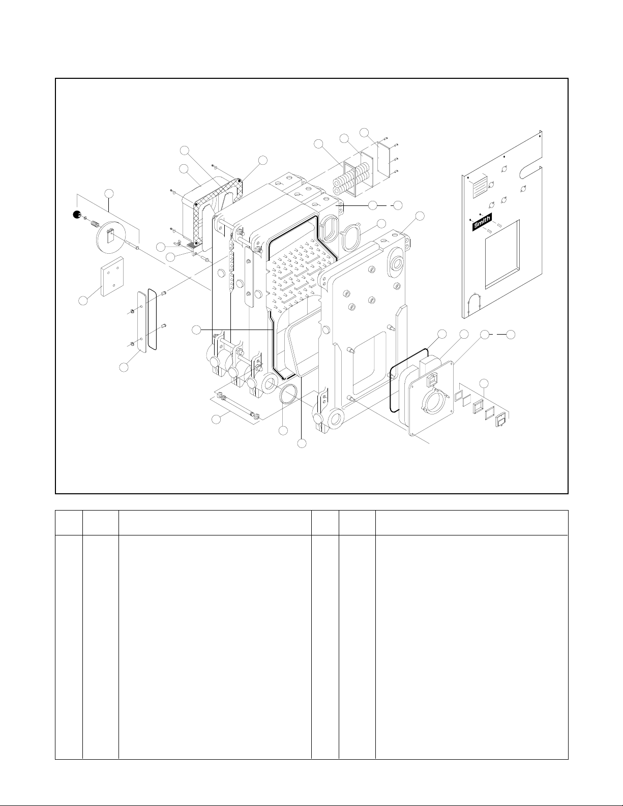
Item Comp.
No. No. Description
1 3638 Front Section
2 3637 Intermediate Section, Plain
3 3641 Intermediate Section, Heater (Optional)
4 3639 Back Section
5 3575 Smokehood 7"
3576 Smokehood 8"
3577 Smokehood 9"
3578 Smokehood 10"
6 69370 Slide Damper
7 — T ankless Heater
(For Intermediate Heater Sections Only)
8 3572 Heater Cover Plate, Blank
9 60333 Heater Co ver Plate Gasket
10 3611 Cleanout Co ver Plate
11 3565 Burner Mounting Plate,
Carlin - 6 1/8" Opening
12 3566 Burner Mounting Plate,
Pow erflame - 73/4" Opening
16
13
14
11
19
25
Item Comp.
No. No. Description
— 3640 Burner Mounting Plate,
Pow erflame - 91/8" Opening
13 60023 Burner Mounting Plate Rope, 1/4"
14 60434 Burner Mounting Plate Insulating Block
14 60430 Burner Mounting Plate Insulating Block
(Beckett Burner)
15 60331 Upper Port Hydronic Seal
16 60332 Lower Port Hydronic Seal
17 60025 Insulating Ceramic Rope
18 — Tie Rod & Hardware
19 — Front Observation P ort
20 70553 Rear Observation Port Assembly
21 71700 Rear Observation Port Cover Plate -
3, 4, 5, 6 Section Boilers
22 74300 Insulating Bolt Hole Tape 3' 6"
23 74302 Insulating T ape 11"
24 69150 Angle Bracket
25 69761 T arget Wall - 3, 4, 5, 6 Section Boilers
12
19A SERIES BOILER
INSTALLATION INSTRUCTIONS
TABLE OF CONTENTS
SECTION DESCRIPTION PAGE SECTION DESCRIPTION PAGE
19A SERIES ISOMETRIC DRAWING 2 10 TANKLESS HEATERS 6
PARTS LIST 2 11 SMOKEHOOD 6
TABLE OF CONTENTS 3 12 BURNER MOUNTING PLATE 7
1 GENERAL INFORMATION 3 13 CLEANOUT COVERS 8
2 BOILER LOCATION 3 14 REAR OBSERVATION PORT 8
3 CODES AND REGULATIONS 3 15 CONTROL LOCATIONS 8
4 CHIMNEY AND BREECHING 3 16 JACKET 8
5 COMBUSTION AND VENTILATION AIR 4 17 SAFETY AND RELIEF VALVES 8
6 ASSEMBLY OF SECTIONS 4 18 CLEANING BOILER WATERWAYS 9
7 HYDROSTATIC TEST 5 19 OWNER'S INSTRUCTIONS 9
8 STEAM PIPING 5 CONTROL TAPPINGS DIAGRAM 10
9 WATER PIPING 6 WARNING 11
PAGE 3
1. GENERAL
19A Series boilers are wet-base, extended surface, vertical
flue design with integral cast flue gas collector for pressurized
firing with oil, gas or combination power burners. Upper and
lower port hydronic seals are of a special material resistant to
petroleum products and compatible with ethylene and
propylene based anti-freeze (non automotive type) which does
not contain corrosion inhibitors to protect aluminum. The flue
gas joints between sections, etc. are sealed using high
temperature (2300°F) ceramic fiber rope. Access to the heating
surface for cleaning is provided from the left hand side of the
boiler through large cast iron cover plates. A slide damper is
provided in the flue gas outlet for back pressure adjustment.
The boilers are supplied completely knocked down for field
assembly, as factory assembled blocks of sections or
completely assembled boiler-burner units. All items should be
inspected for damage upon receipt, and any damage reported
to the wholesaler and trucker. All components should be
stored in a clean, dry area.
The boilers are conservatively rated for high efficiency
performance with capability for down-firing to match connected
load. The large OBROUND upper port provides transfer area
above the water surface for dry steaming at full load.
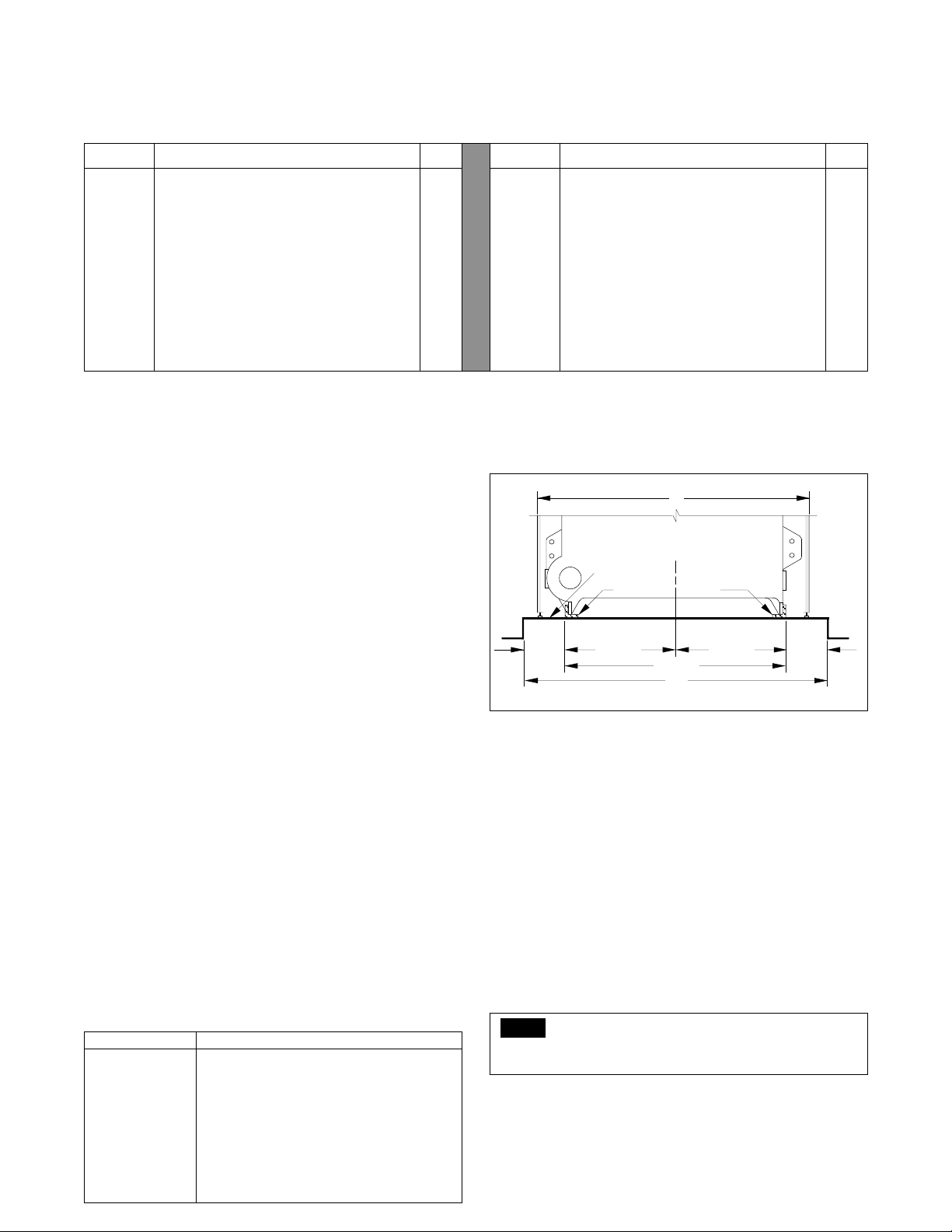
2. BOILER LOCATION
The boiler must be installed on a smooth, level, noncombustible floor or pad as close to the chimney or vent
location as possible to minimize breeching length. Allow
clearance around the boiler for piping, service, maintenance,
cleaning and tankless coil removal. Approximately 30 inches
on the sides is a minimum (Check local code requirements).
Do not install electrical conductors in floor or pad under boilers.
See FIGURE 1 for boiler floor pad requirements, and TABLE
1 for minimum required pad length.
3. CODES AND REGULATIONS
All work in connection with the boiler, burner and controls
must be performed in strict accordance with requirements of
state and local authorities having jurisdiction over boiler
installations.
32"
JACKET SIDE PANEL
OF BOILER
FLOOR
OR PAD
1 1/2" x 2 1/2" ANGLES
4 5/32" 12 27/32" 12 27/32"
C
L
25 21/32"
34"
4 5/32"
FIGURE 1
In the absence of such local requirements, the following should
govern:
A.S.M.E. Section IV - “Heating Boilers"
A.S.M.E. Section VI - “Care and Operation of Boilers”
ANSI/NFPA 31 - “Installation of Oil Burning Equipment”
ANSI/Z223.1 - “National Fuel Gas Code”
ANSI/NFPA 70 - “National Electrical Code”
4. CHIMNEY AND BREECHING
The breeching connection between boiler and chimney should
be as direct as possible with the minimum number of elbows or
bends. It should pitch upwards to the chimney at a rate of 1/4
inch per foot of horizontal run. Generally, the breeching and
chimney should be the same diameter as the boiler outlet
connection.
TABLE 1
Boiler No. Min. Recommended Pad Length
19-*-3 30"
19-*-4 36"
19-*-5 42"
19-*-6 48"
19-*-7 54"
19-*-8 60"
19-*-9 66"
19-*-10 72"
19-*-11 78"
19-*-12 84"
NOTE
11 and 12 section uses adapter collar for connection to
12" diameter vent system.
For fuel conservation and stable burner performance, the
vent connection from the boiler should not include a barometric
draft control or other opening unless the venting system can
develop an excessive draft, or is required by code.
PAGE 4
19A SERIES BOILER
INSTALLATION INSTRUCTIONS
5. COMBUSTION AND VENTILATION AIR
An adequate supply of air for the boiler room must be provided
to allow complete combustion of fuel and ventilation of the
room to avoid excessively high ambient temperature. Air inlet
by natural ventilation directly from the outside shall have
total free area of not less than one sq. in. per 14,000 BTU
per hour of input of all fuel burning appliances in the boiler
room.
Where combustion air must be obtained through ducts, see
ANSI/NFPA 31 or ANSI Z223.1 for requirements.
If mechanical combustion air supply is required, the system
must be approved by the local authorities, and should provide
at least 30 CFM per gallon of oil and 0.25 CFM per MBH of
gas input to the boilers.
Ventilation air, if required, must be in addition to the
combustion air quantities called for above.
6. ASSEMBLY OF SECTIONS
When boilers are delivered to the job site, each item should
be inspected closely for possible shipping damage. Scars or
nicks in the port sealing surfaces may allow leakage. Do not
attempt to use any section that has been damaged in the
port seal area.
When ready to commence assembly, recommended on a
level pad, place the angle rails in position parallel with each
other with the 2" legs on the floor and measuring 25-21/32
inches outside dimension. Be sure to align the center of the
boiler with the center line of the pad. If no pad is provided,
shim and grout under the angles to make them level and
provide support along the full length. See FIGURE 1. Clean
hydronic gasket recesses and rope groove with a wire brush,
taking care not to damage machine surface.
See TABLE 2 for proper location of sections.
TABLE 2
3 SECT
4 SECT
5 SECT
6 SECT
7 SECT
8 SECT
9 SECT
10 SECT
11 SECT
12 SECT
F
F
F
F
F
F
F
F
F
F
B
H
H
P
H
P
H
P
P
P
P
P
B
P
H
P
H
H
P
P
P
B
H
H
P
H
P
P
H
P
P
B
H
P
H
H
P
H
P
B
P
H
B
P
H
H
P
P
H
H
P
B
P
P
H
P
H
B
H
P
B
P
P
H
B
F = Front Section
P = Plain intermediate section
H = Heater intermediate section-Optional, must be ordered.
B = Back Section
CAUTION
Due to the fact that the sections are top heavy, it is
absolutely necessary that the back section be supported
in such a manner as to prevent its falling and causing
potential serious bodily injury while preparing to add the
next section. One such way would be to insert a piece of
3" x 36" piping in the lower port.
NOTE
Some sections may need shims under support feet to align
with other sections.
Stand the back section in place with the feet on and in the
angle iron rails. Support the section as required to prevent it
from falling forward or rearward. Clean hydronic gasket
recesses and rope groove with a stiff wire brush. Apply
spray-on adhesive (supplied with the boiler) to rope groove
to hold wicking in place during assembly.
CAUTION
Do not spray adhesive into the hydronic seal ports.
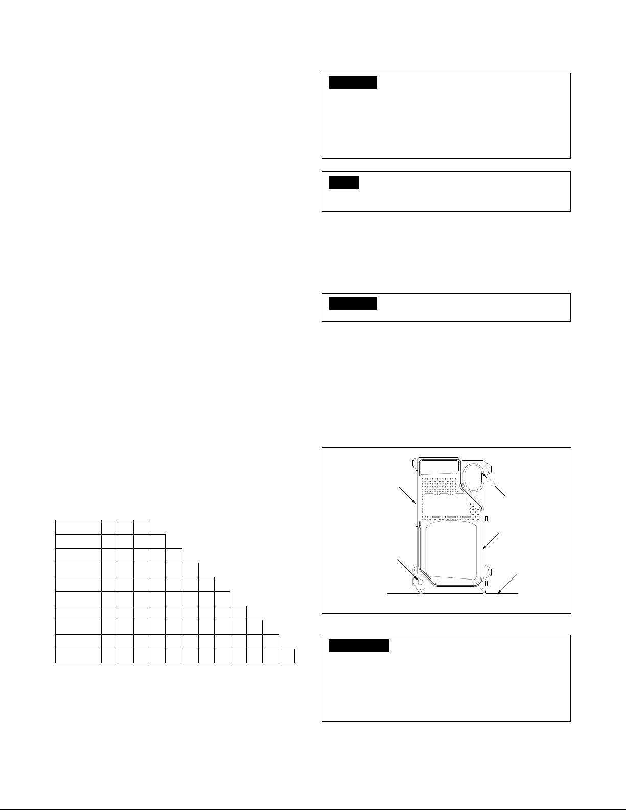
Apply a length of wicking avoiding bends and twists. Be sure
ends extend past the cleanout cover opening. (See FIGURE
2) Place the upper and lower hydronic seals in the recessed
section taking care not to dislodge the rope or the hydronic
seals. Inspect the alignment of the sections through the open
ports and, if properly aligned, install the draw rods with nuts
drawn hand-tight. (See FIGURE 3.) Plumb the sections before
applying torque to the upper right and lower left draw rods.
Maintain finger-tight torque on upper left and lower right draw
rods.
CLEANOUT COVER
HEATING
SURFACE
LOWER PORT
SECTIONAL VIEW
UPPER PORT
CERAMIC ROPE
JOINT SEAL
FLOOR
FIGURE 2
IMPORTANT
The upper and lower ports should be drawn up metal to
metal around the outside of the hydronic seal. Metal to
metal conditions will not occur at any other location.
Avoid excessive torque on upper left and lower right
draw rods, which may warp the section. See FIGURE 3
for correct alignment of the seal.
Assemble additional sections as described above.
After draw rods are hand tight, torque as shown in TABLE 3.
 Loading...