

Page 1
19 561 0121 00 – EN
21 / 07 / 15
First issue
REV. DOC.
DATE
NOTES
INSTALLATION REQUIREMENTS
WD6010 – GW6010
SMEG S.p.A. thanks you for having chosen this product.
Preliminary operations for Start-up, at Customer's care:
any necessary work of room preparation
prearrangement of properly operating systems, in compliance with the requirements and
regulations in force
machine positioning
Refer to the instructions in this manual for detailed instructions on the above.
SMEG S.p.A. disclaims any liability for damage to persons or property resulting from defective systems
or not compliant with the regulations, for improper installation of the appliance and/or accessories
made by unauthorized personnel.
Any operation on the appliance by unauthorized personnel will invalidate the warranty.
1
Page 2
WD6010-GW6010 INSTALLATION REQUIREMENTS
CAUTION
It is essential that the electrical system to which the machine is connected complies with current regulations.
All electrical testing operations and equipment electrical installation should be made by qualified personnel.
The competent personnel is responsible to check that the earthing is efficient.
Any components must always be replaced with genuine spare parts.
CIRCUIT-BREAKER
A CIRCUIT-BREAKER must be installed for each appliance.
Circuit-breaker characteristics:
a. Omnipolar: must break all live conductors;
b. Easily accessible to the user;
c. Easily operated (no tool must be required);
d. Located in close proximity to the appliance;
e. Clearly marked as the appliance circuit-breaker
The same specifications apply to the mains switch on the machine: It must be maintained Easily accessible. Do not
place objects in a way that limits its accessibility.
A PROTECTIVE DEVICE specifically for the appliance (e.g. magnetothermal breaker or fuse on every phase,
suitably rated for the electrical data stated) should be installed in the room’s electrical panel.
ELECTRICAL SYSTEM REQUIREMENTS
Refer to the Technical Data for the required connections characteristics.
The device is supplied without a plug, with a cable with insulated wire terminals: The electrical connection of the device
must be carried out with a permanent connection.
2
Page 3
WD6010-GW6010 INSTALLATION REQUIREMENTS
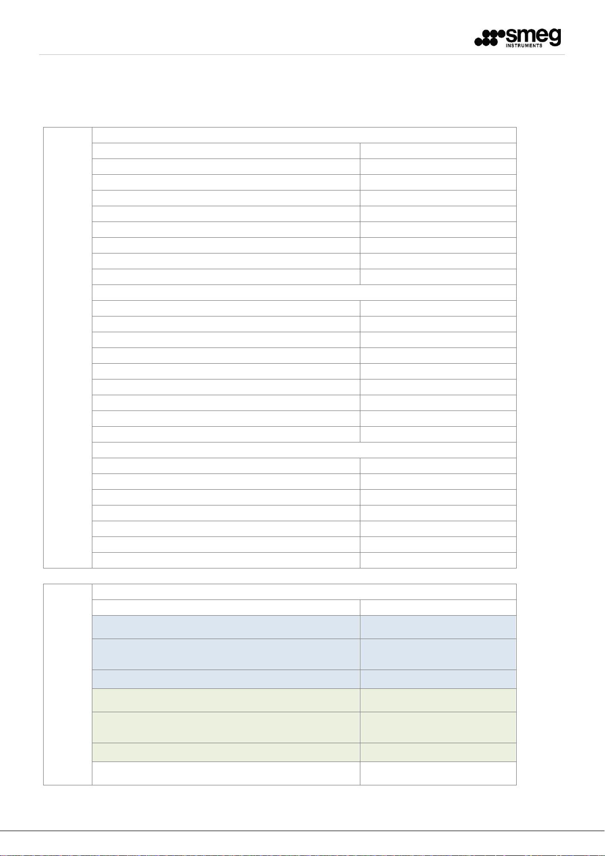
DATI TECNICI - TECHNICAL DATA
Italiano - English
Collegamenti Idraulici
Water connections
"CW" ACQUA FREDDA - COLD WATER
Connessione - Connection:
3/4" maschio-male - DN20
Portata min/max - Min/Max flow rate:
4 - 12 lt/min
Pressione dinamica min. - Min. flow pressure:
100 kPa (1,0 bar)
Pressione max. - Max. pressure:
600 kPa (6,0 bar)
Temperatura max. - Max. temperature:
35 °C
Durezza max. - Max. hardness:
10 °f
Ferro Max - Fe2+ / Fe3+ [max]
0,5 ppm
pH:
7÷8
"HW" ACQUA CALDA - WARM WATER
Connessione - Connection:
3/4" maschio-male - DN20
Portata min/max - Min/Max flow rate:
4 - 12 lt/min
Pressione dinamica min. - Min. flow pressure:
100 kPa (1,0 bar)
Pressione max. - Max. pressure:
600 kPa (6,0 bar)
Temperatura max. - Max. temperature:
60°C
Durezza max. - Max. hardness:
10 °f
Ferro Max - Fe2+ / Fe3+ [max]
0,5 ppm
pH:
7÷8
"DW" ACQUA DEMI - DEMI WATER
Connessione - Connection:
3/4" maschio-male - DN20
Portata min/max - Min/Max flow rate:
4 - 12 lt/min
Pressione dinamica min. - Min. flow pressure:
100 kPa (1,0 bar)
Pressione max. - Max. pressure:
600 kPa (6,0 bar)
Temperatura max. - Max. temperature:
60°C
Durezza max. - Max. hardness:
0 °f (0ppm CaCO3)
Conducibilità max. /pH - Max. conductivity / pH:
30 µS/cm / 5÷8 pH
Collegamenti Elettrici
Electrical connections
"EC" Connessioni elettriche - Electrical connections
Tipo - Type:
Standard
Tensione standard - Standard Voltage:
400V 3N~ / PE / 50Hz / 24A
Protezione elettrica richiesta nell'impianto -
Electrical protection required:
3P+N, 32 A
Cavo e sez.min - Cable and min. section:
5 x 6 mm2
Tensione configurabile - Configurable Voltage:
230V 3~ / PE / 50Hz / 36A
Protezione elettrica richiesta nell'impianto -
Electrical protection required:
3P, 40 A
Cavo e sez.min - Cable and min. section:
4 x 6 mm2
Potenza - Power:
13 kW
3
Page 4
WD6010-GW6010 INSTALLATION REQUIREMENTS
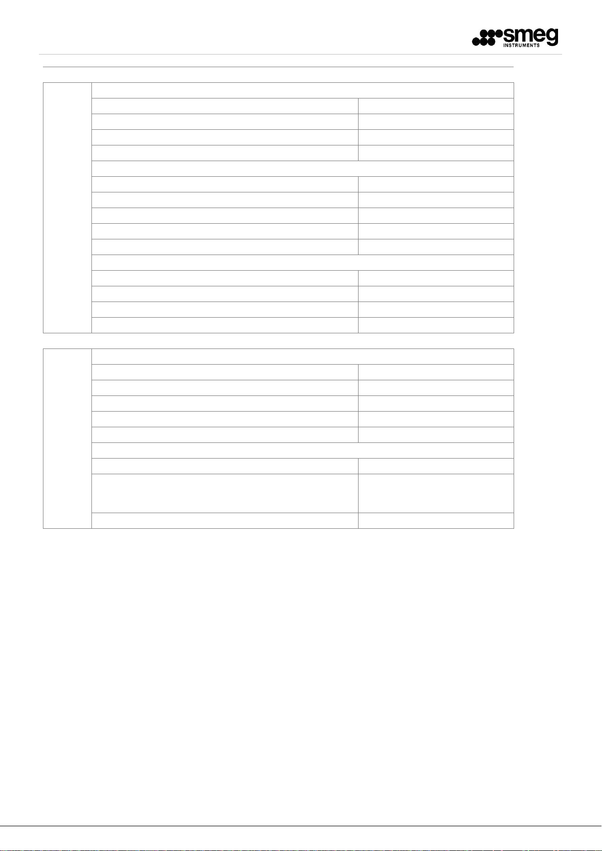
Scarico acqua e Sfiato vapori
Drain and exhaust
"EX" SCARICO VAPORI - EXHAUST DUCT
Connessione - Connection:
ø 50 mm
Portata max - Peak flow rate:
approx.220-250 m3/h
Temperatura max. - Max. temperature:
95 °C
"FD" SCARICO ACQUA A PAVIMENTO (standard) - DRAIN FLOOR (standard)
Connessione - Connection:
ø 50 mm
Portata max - Peak flow rate:
50 lt/min
Altezza max. - Max. height:
50 mm
Temperatura max. - Max. temperature:
95 °C
"D" SCARICO ACQUA A PARETE (opzionale) - DRAIN WALL (optional)
Connessione - Connection:
ø 40 mm
Portata max - Peak flow rate:
30 lt/min
Altezza max. - Max. height:
0,8 m
Temperatura max. - Max. temperature:
95 °C
Altri
Others
PESI – WEIGHTS
Netto totale massimo- total net max:
280 kg
Lordo totale massimo - total gross max:
310 kg
Max all'uso - Max. on working:
380 kg
Carico a pavimento - Floor load:
600 daN/m2 (kg/m2)
AMBIENTE - ENVIRONMENT
Temperatura - Temperature:
T = 10 - 40 °C
Umidità max - umidity max:
80% per temperature sino a 31°C
con diminuzione lineare sino a 50%
alla temperatura di 40°C.
Rumorosità - Noise level:
< 66 dB (A)
4
Page 5

WD6010-GW6010 INSTALLATION REQUIREMENTS
NOTES
1. It is the customer’s responsibility to insure that the specified pressure ranges are respected (water mains
and, if applicable, steam and air pressure). The pressure has to be measured at the point of connection to
the device.
2. It is customer responsibility to provide, if necessary, shock arrestors and / or pressure regulators to
eliminate water hammer conditions.
3. It is customer responsibility to provide shutoff valves for incoming cold, hot, demineralized water, and
steam and air (optional services). The valves must always be easily accessible to the operator.
4. It is the customer responsibility to provide a proper drainage system, according with national and local
regulations, considering the device requirements. It is necessary to prevent backflow to the device.
5. If the machine is connected to free discharge pipes for steam/fume exhaust, condensation deposit in
pipes must be prevented; moreover, the section must be equal or higher than the given dimensions and
there must not be areas with condensation deposit. In case of fume extraction, the clearances as shown
in the schemes must be observed. At any rate the indicated flow rates must be observed and the
materials must be resistant to the expected temperatures.
6. Even in case of two or more machines installed side by side, the service area required must be respected.
7. In case of double-door machines, it is customer responsibility to provide barrier wall, for the separation
between loading side (unclean side) and unloading side (clean side).
Smeg S.p.A.
Instruments Division
Via Leonardo da Vinci, 4 – 42016 GUASTALLA - R.E.
Tel +39 0522 8211 – Fax +39 0522 821 592
E-mail: instruments@smeg.it – service.instruments@smeg.it
www.smeg-instruments.com
5
Page 6

IT - DOPPIA PORTA
EN - DOUBLE DOOR
(860460)
VALVOLE NON FORNITE
SHUT-OFF VALVES NOT SUPPLIED
Via Leonardo da Vinci,4
Via Leonardo da Vinci,4
42016 Guastalla (RE) ITALIA
42016 Guastalla (RE) ITALIA
S.p.A
S.p.A
LA RIPRODUZIONE O LA CESSIONE DEL PRESENTE
DISEGNO DEVONO ESSERE AUTORIZZATE DALLA
ANY REPRODUCTION OR TRANSFER OF THE
PRESENT DRAWING MUST BE AUTHORIZED BY
FORM. A4
“SMEG” SPA
“SMEG” SPA
DOC. - DOC.ID
PREDISPOSIZIONE IMPIANTI
INSTALLATION
REQUIREMENTS
COD. DOC.
195610121.00 - A
DATA - DATE
21.07.2015
Page 7

750
PASSAGGIO MURO
WALL OPENING
650
LARGHEZZA MACCHINA
UNIT WIDTH
IT - DOPPIA PORTA
EN - DOUBLE DOOR
(860460)
PROFONDITA’ MACCHINA
712
UNIT DEPTH
30
MANIGLIA
753
70
HANDLE
VISTA FRONTALE LATO CARICO
FRONT VIEW LOADING SIDE
WALL OPENENING
1990
APERTURA MURO -
SEZIONATORE ELETTRICO
MAINS SWITCH
LATO SCARICO (PULITO)
UNLOADING SIDE (CLEAN)
- UNIT HEIGHT
1942
LATO SCARICO (PULITO)
UNLOADING SIDE (CLEAN)
ALTEZZA MACCHINA
OUT
450
VISTA LATERALE
SIDE VIEW
IN
LATO CARICO (SPORCO)
LOADING SIDE (UNCLEAN)
860
Via Leonardo da Vinci,4
Via Leonardo da Vinci,4
42016 Guastalla (RE) ITALIA
42016 Guastalla (RE) ITALIA
S.p.A
S.p.A
852
LATO CARICO (SPORCO)
LOADING SIDE (UNCLEAN)
LA RIPRODUZIONE O LA CESSIONE DEL PRESENTE
DISEGNO DEVONO ESSERE AUTORIZZATE DALLA
ANY REPRODUCTION OR TRANSFER OF THE
PRESENT DRAWING MUST BE AUTHORIZED BY
FORM. A4
“SMEG” SPA
“SMEG” SPA
VISTA IN PIANTA
PLANT VIEW
DOC. - DOC.ID
PREDISPOSIZIONE IMPIANTI
INSTALLATION
REQUIREMENTS
MAX 120
AREA LIBERA PER ACCESSO
SERVICE CLEARANCE (BOTH SIDES)
SEZIONATORE ELETTRICO
MAINS SWITCH
AREA LIBERA PER ACCESSO FUNZIONALE
CLEARANCE AREA - FUNCTIONAL ACCESS (BOTH SIDES)
COD. DOC. DATA - DATE
195610121.00 - B
(AMBO I LATI)
(AMBO I LATI)
21.07.2015
Page 8

IT - DOPPIA PORTA
NOTA: LE CONNESSIONI POSSONO ESSERE PREDISPOSTE
ANCHE SUL LATO SINISTRO
NOTE: THE CONNECTION CAN BE ARRANGED
ALSO ON THE LEFT SIDE
SCARICO VAPORI
STEAM AND AIR EXAUST
EX
90
EN - DOUBLE DOOR
(860460)
30
30
EC
2000
HW CW DW
165
AREA POSSIBILE SCARICO
DRAIN LOCATION AREA
4 PIEDI Ø50
FEET Ø50X4
FD
VISTA FRONTALE
FRONT VIEW LOADING SIDE
430
Ø 50
FD
325
84
VISTA IN PIANTA - BASAMENTO
PLANT - BASAMENT VIEW
480
110
Max 1200
Max 600
LATO SCARICO (PULITO)
UNLOADING SIDE (CLEAN)
140
50
85 543
LATO CARICO (SPORCO)
LOADING SIDE (UNCLEAN)
Max 1600
EX
Ø50
50
VISTA IN PIANTA- TOP
PLANT-TOP VIEW
260
Via Leonardo da Vinci,4
Via Leonardo da Vinci,4
42016 Guastalla (RE) ITALIA
42016 Guastalla (RE) ITALIA
S.p.A
S.p.A
LA RIPRODUZIONE O LA CESSIONE DEL PRESENTE
DISEGNO DEVONO ESSERE AUTORIZZATE DALLA
ANY REPRODUCTION OR TRANSFER OF THE
PRESENT DRAWING MUST BE AUTHORIZED BY
FORM. A4
“SMEG” SPA
“SMEG” SPA
DOC. - DOC.ID
PREDISPOSIZIONE IMPIANTI
INSTALLATION
REQUIREMENTS
COD. DOC. DATA - DATE
195610121.00 - C
21.07.2015
Page 9

IT - PORTA SINGOLA
EN - SINGLE DOOR
(860457)
VALVOLE NON FORNITE
SHUT-OFF VALVES NOT SUPPLIED
Via Leonardo da Vinci,4
Via Leonardo da Vinci,4
42016 Guastalla (RE) ITALIA
42016 Guastalla (RE) ITALIA
S.p.A
S.p.A
LA RIPRODUZIONE O LA CESSIONE DEL PRESENTE
DISEGNO DEVONO ESSERE AUTORIZZATE DALLA
ANY REPRODUCTION OR TRANSFER OF THE
PRESENT DRAWING MUST BE AUTHORIZED BY
FORM. A4
“SMEG” SPA
“SMEG” SPA
DOC. - DOC.ID
PREDISPOSIZIONE IMPIANTI
INSTALLATION
REQUIREMENTS
COD. DOC. DATA - DATE
195610121.00 - D
21.07.2015
Page 10

IT - PORTA SINGOLA
EN - SINGLE DOOR
(860457)
650
LARGHEZZA MACCHINA
UNIT WIDTH
- UNIT HEIGHT
1942
ALTEZZA MACCHINA
LARGHEZZA MACCHINA
712
UNIT DEPTH
30
753
70
MANIGLIA
HANDLE
IN
860
50
712
VISTA FRONTALE
FRONT VIEW
VISTA IN PIANTA
PLANT VIEW
SEZIONATORE ELETTRICO
MAINS SWITCH
AREA LIBERA PER ACCESSO
SERVICE CLEARANCE (BOTH SIDES)
450
SEZIONATORE ELETTRICO
MAINS SWITCH
AREA LIBERA PER ACCESSO FUNZIONALE
CLEARANCE AREA - FUNCTIONAL ACCESS
VISTA LATERALE
SIDE VIEW
(AMBO I LATI)
Via Leonardo da Vinci,4
Via Leonardo da Vinci,4
42016 Guastalla (RE) ITALIA
42016 Guastalla (RE) ITALIA
S.p.A
S.p.A
LA RIPRODUZIONE O LA CESSIONE DEL PRESENTE
DISEGNO DEVONO ESSERE AUTORIZZATE DALLA
ANY REPRODUCTION OR TRANSFER OF THE
PRESENT DRAWING MUST BE AUTHORIZED BY
FORM. A4
“SMEG” SPA
“SMEG” SPA
DOC. - DOC.ID
PREDISPOSIZIONE IMPIANTI
INSTALLATION
REQUIREMENTS
COD. DOC. DATA - DATE
195610121.00 - E
21.07.2015
Page 11

SISTEMA
ASPIRAZIONE
AIR VENTING
SYSTEM
SCARICO VAPORI
STEAM AND AIR EXHAUST
EX
30
30
NOTA: LE CONNESSIONI POSSONO ESSERE PREDISPOSTE
ANCHE SUL LATO SINISTRO, O SUL RETRO
NOTE: THE CONNECTION CAN BE ARRANGED
ALSO ON THE LEFT SIDE OR ON THE REAR.
EC
2000
IT - PORTA SINGOLA
EN - SINGLE DOOR
(860457)
FD
VISTA FRONTALE
FRONT VIEW
AREA POSSIBILE SCARICO (ACQUA)
DRAIN LOCATION AREA
430
Ø 50
165
110
CW
DW
HW
Max 1200
Max 600
LATO SCARICO (PULITO)
UNLOADING SIDE (CLEAN)
140
Max 1600
C W, HW ,
DW, EC (D)
VISTA LATERALE
SIDE VIEW
75
15
AMBO I LATI
15015085
BOTH SIDES
4 PIEDI Ø50
FEET Ø50X4
84
VISTA IN PIANTA - BASAMENTO
PLANT - BASAMENT VIEW
Via Leonardo da Vinci,4
Via Leonardo da Vinci,4
42016 Guastalla (RE) ITALIA
42016 Guastalla (RE) ITALIA
S.p.A
S.p.A
480
FD
325
FORM. A4
50
85 543
LATO CARICO (SPORCO)
LOADING SIDE (UNCLEAN)
LA RIPRODUZIONE O LA CESSIONE DEL PRESENTE
DISEGNO DEVONO ESSERE AUTORIZZATE DALLA
ANY REPRODUCTION OR TRANSFER OF THE
PRESENT DRAWING MUST BE AUTHORIZED BY
“SMEG” SPA
“SMEG” SPA
DOC. - DOC.ID
PREDISPOSIZIONE IMPIANTI
INSTALLATION
REQUIREMENTS
EX
Ø50
260
50
VISTA IN PIANTA- TOP
PLANT-TOP VIEW
COD. DOC. DATA - DATE
195610121.00 - F
21.07.2015
 Loading...