


SGR10S
Betriebsanleitung
Operating Instructions
Istruzioni per l’uso

ENGLISH
SGR10S Table of Contents
& ENGLISH
Table of Contents
1 Introduction _______________________________________________________2
2 Before starting _____________________________________________________3
2.1 Finding your way around these operating instructions__________________________3
2.2 Correct use___________________________________________________________3
2.3 Assembly and function __________________________________________________4
2.4 Sealing process sequence_______________________________________________4
2.5 General safety information _______________________________________________5
2.6 Installation ____________________________________________________________5
3 Basic functions_____________________________________________________6
3.1 Commissioning ________________________________________________________6
3.2 Operation_____________________________________________________________7
3.3 Setting the temperature regulator__________________________________________8
4 Fault clearance and maintenance ______________________________________9
4.1 Fault clearance checklist _________________________________________________9
4.2 Customer Service_____________________________________________________10
4.3 Maintenance plan _____________________________________________________10
4.4 Spare parts service____________________________________________________11
4.5 Spare parts order – product number allocation ______________________________13
4.6 Sealing die___________________________________________________________13
4.7 Guide die____________________________________________________________14
4.8 Spare parts order – Overview____________________________________________15
5 Technical data ____________________________________________________16
5.1 Circuit and wiring diagram 230V__________________________________________16
5.2 Circuit and wiring diagram 100 / 115V_____________________________________17
5.3 Specifications ________________________________________________________18
6 Declaration of conformity____________________________________________19
Page GB 1 9.696.035 Version 1.02
Note
SGR10S Introduction Chapter 1
ENGLISH
1 Introduction
Preface
First of all we would like to sincerely thank you for buying the SGR10S cycle sealing device.
In these instructions you will find information about the device, its function and operation.
Please read these operating instructions thoroughly before putting the device into
operation so that you become familiar with its capabilities and can use its functions
optimally.
F Always keep these instructions close to the device.
Important notice:
This device is a film rotary sealing device for closing sterile barrier systems.
Please observe chapter "Correct use " in these operating instructions in this respect.
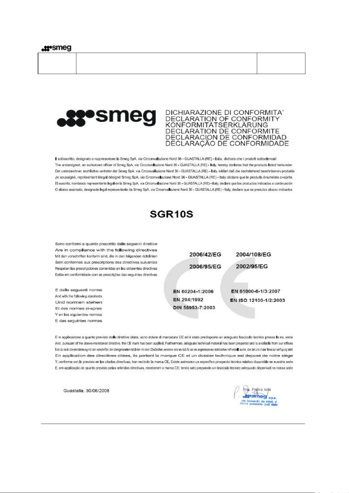
In accordance with the purpose, CE certification based on the EU Directives indicated below
has been affixed: 2006/42/EC and 2006/95/EC.
Directive 93/042 EEC is not applicable to welding and sealing devices.
The limit values of IEC 60601-1 cannot be used with electrical re-tests.
The manufacturer shall accept no liability whatsoever for damage caused by tests which are not
listed in the Declaration of Conformity.
Because we are constantly improving our products
we reserve the right to update these operating
instructions and the functions described in them
accordingly.
Should you nevertheless notice errors or points that
are unclear, please let us know about them.
These operating instructions are valid for products
as from the date of manufacture of 07/2008
Page GB 2 9.696.035 Version 1.02

SGR10S Before starting Chapter 2
ENGLISH
2 Before starting
2.1 Finding your way around these operating instructions
In this ch apter you will find information about using the
device correctly, its function and advice about
Chapter 2
Before starting
Chapter 3
Basic functions
operation and installation.
PLEASE READ THIS ESSENTIAL
INFORMATION!
Adjusting and operating the device are explained here.
Chapter 4
Fault clearance and
maintenance
Chapter 5
Technical data
Chapter 6
Declaration of Conformity
Instruction on finding disturbance sources and
rectifying malfunctions.
Here you will find out about necessary servicing,
wearing parts and spare parts as well as about the
allocation of product numbers for spare parts orders.
Here you see the circuit and wiring diagram as well as
the device specification.
In this chapter you will find the Declaration of
Conformity for the SGR10S rotary sealing device.
2.2 Correct use
The SGR10S device is only designed for trade and industrial use and must only be used for the
prescribed purpose.
The SGR10S device is used for the continuous closure of sterile barrier systems made of paper
or paper laminate films.
The SGR10S cycle sealing device is not suitable for sealing polyethylene films, PVC
foils, foils and polypropylene films.
Device performance is dependant on the condition of the sealing material used.
Page GB 3 9.696.035 Version 1.02

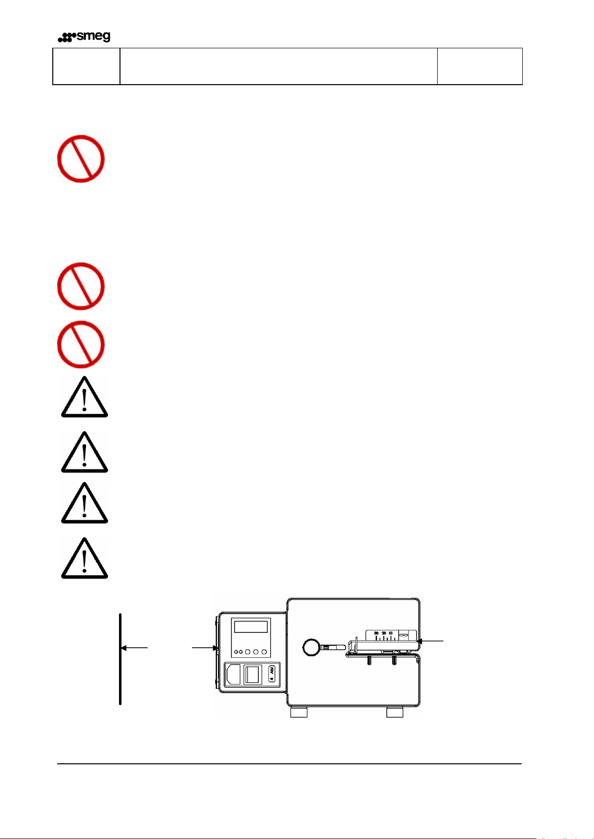
Power connection
Power switch
Mains fuses
Adjustable
Temperatur
e
ENGLISH
SGR10S Before starting Chapter 2
2.3 Assembly and function
regulator
sealing edge setting
2.4 Sealing process sequence
Step 1: After the sterilisation packaging has been inserted the transport
switches on automatically.
Step 2: The sterilisation packaging is now transported and the sealing seam area is
heated up by the heating dies positioned above and below to the sealing
temperature set.
Step 3: The sealing seam, which is now heated up, is pressed through the sealing rolls
and thus sealed.
Step 4: The completed sterilisation packaging is transported to the withdrawal side.
Step 5: If no further material to be sealed is fed in the transport switches off after
approximately 30 seconds.
Page GB 4 9.696.035 Version 1.02
Œ
•
SGR10S Basic functions Chapter 3
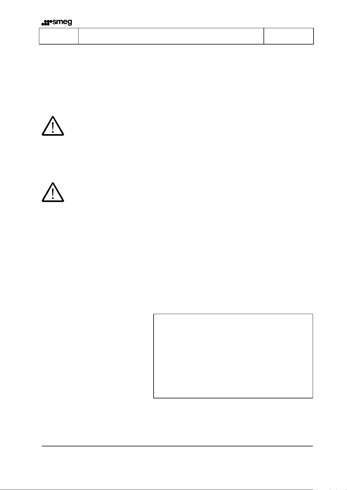
2.5 General saf ety information
ENGLISH
The device must not be installed and operated by persons under 14
years of age.
I
The device must not be operated unattended.
Switch the device off or pull out the mains power plug when the
device is not in use.
2.6 Installation
I
I
The device must not be installed and operated in potentially
explosive areas.
Only use power outlets with a grounding conductor and a stable
voltage supply.
The device must only be set up in dry surroundings. Heavy dust,
steam, water drips or water spray compromise the function of the
device.
Please ensure that the operating voltage corresponds with the data
on the device type plate.
Please do not lift and transport the device at the sealing edge setting!
Œ
Leave a gap of 8 inches between the device and the wall. •
200 mm
Page GB 5 9.696.035 Version 1.02
Po
wer connection
Power switch
Temperatur
e regulator
ENGLISH
SGR10S Basic functions Chapter 3
3 Basic functions
3.1 Commissioning
Step 1: Plug power cable into power connection.
Step 2: Switch device with power switch to setting "1".
Control light in the switch illuminates.
Step 3: Set the desired sealing temperature on the temperature regulator as described in
chapter 3.3.
Step 4: As soon as the set sealing temperature is displayed the device is heated up and
ready for operation.
Page GB 6 9.696.035 Version 1.02
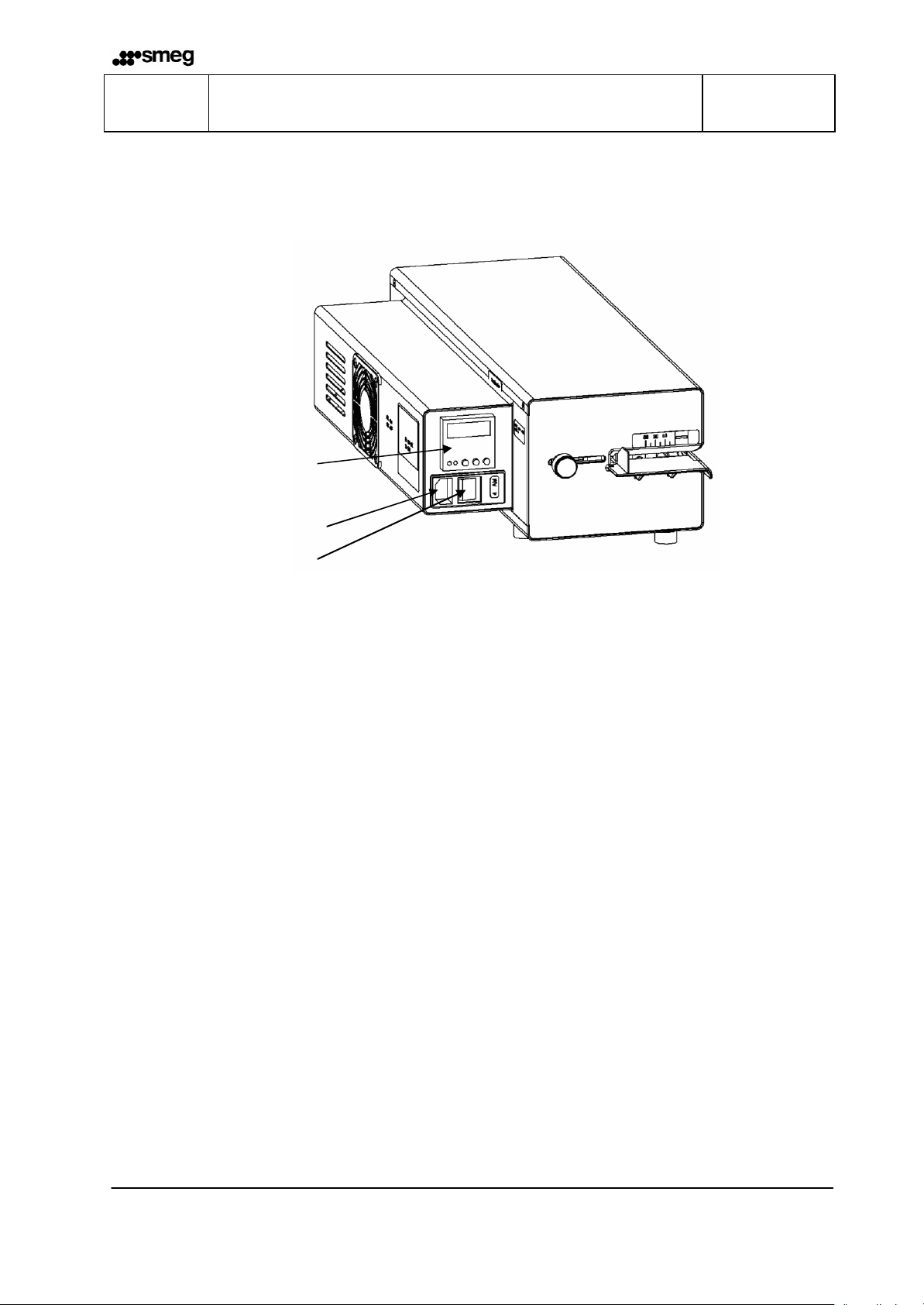
Adjustable
Knurled screw
SGR10S Basic functions Chapter 3
ENGLISH
3.2 Operation
Step 1: Set the desired sealing edge width. After the knurled screw has been loosened the
lower insertion plate can be set infinitely variably for sealing widths of 0 - 35mm.
Step 2: Insert packaging into the device over the insertion plate from the left.
Step 3: Take out sealed packaging at the exit side and briefly leave to cool down.
Inspecting the sealing seam
F
If points that are not tightly sealed are apparent the sealing temperature must
be increased. If the foil melts the set temperature is too high.
The appropriate sealing temperature must be identified by performing test
sealings.
sealing edge setting
Page GB 7 9.696.035 Version 1.02
ENGLISH
• Ž • • ‘ Œ • Ž • • ‘
-1 +1
SGR10S Basic functions Chapter 3
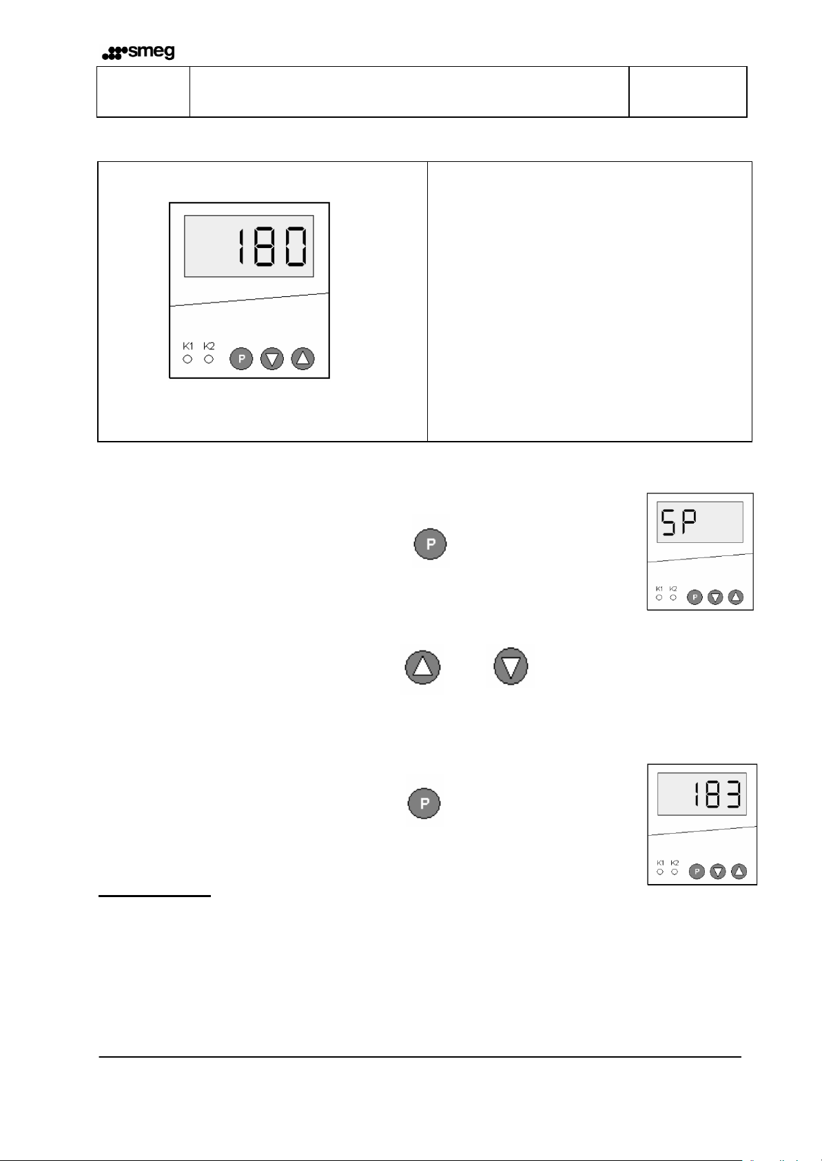
3.3 Setting the temperature regulator
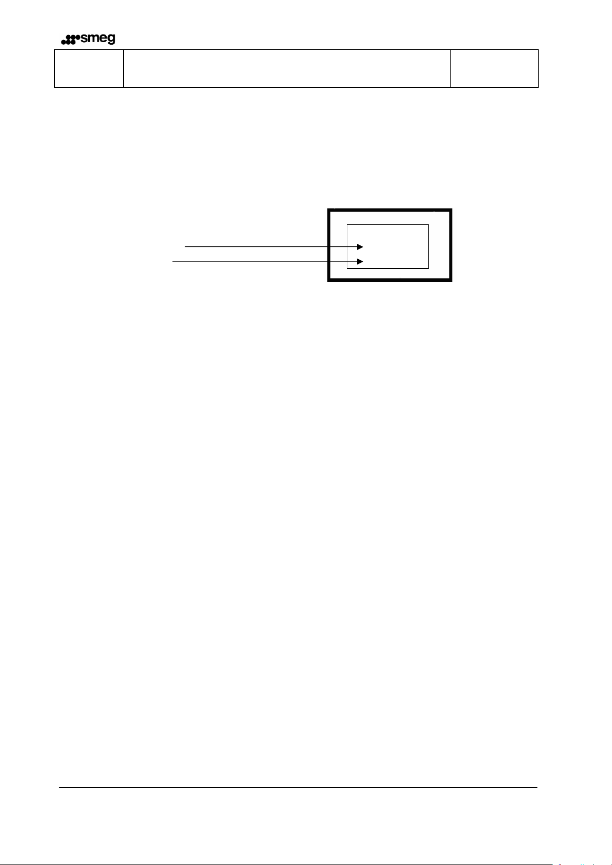
Œ
Temperature display
Motor - start relay indicator
Temperature regulator indicator
Target temperature entry
Temperature value
Temperature value
Entering the target temperature
Button is pressed once 1 x
Setting the temperature with keys +1 -1
Entry is activated 2 x
Factory setting:
Target temperature 180°C
Unit of temperature °C
Page GB 8 9.696.035 Version 1.02
ENGLISH
SGR10S Fault clearance and maintenance Chapter 4
4 Fault clearance and maintenance
4.1 Fault clearance checklist
Malfunction Possible cause Remedy
Network connection
Check network connection; connect
another plug if necessary
Replace mains fuse.
In the event of fuses blowing
repeatedly you must compulsorily
have the device checked!
Increase target temperature
Device does not switch on
Power cable not plugged in
Power cable defective Replace power cable
Mains fuse
Target temperature too low
Overtemperature cutout has
Device is not heating
triggered
Temperature regulator
Heating element
Solid state relay
Target temperature not reached
Motor defective
No material transport
Microswitch defective
Non-symmetrical material
transport
Toothed damaged
Tooth belt not transporting
Loud running noise Motor defective
Sealing temperature too low
Sealing seam does not
hold up
Clearance between sealing dies is
too large
Sealing seam distorted or
melted
Sealing temperature too high
Press in overtemperature cutout.
In the event of repeated triggering
you must compulsorily have the
device checked!
Replace temperature regulator
Check heating elements and replace
if necessary
Replace solid state relay
Replace motor
Replace microswitch
Replace toothed belt
Check toothed belt tension
Replace motor
Increase sealing temperature
Set the sealing die to 0.5mm
Reduce sealing temperature
Page GB 9 9.696.035 Version 1.02

SGR10S Fault clearance and maintenance Chapter 4
ENGLISH
4.2 Customer Service
You can contact your Customer Service Monday to Friday from 8.30 am
(
to 6.00 pm on +3 9 (0)522 821 521.
4.3 Maintenance plan
As is the case with all technical device your device is also subject to
technical wear.
In order to guarantee that your device is permanently ready to use it should
Maintenance cycle
At least every
3. Month
According to
load,
at least once
per year
Key:
be serviced by a qualified person at least once per year.
PTFE strip
Guide die
PTFE strip
Sealing
die
Pressure
roller
Toothed
belt
Check
Page GB 10 9.696.035 Version 1.02
Replace
SGR10S Fault clearance and maintenance Chapter 4
4.4 Spare parts service
F
• Enter address, fax number and
order number
• Enter serial number
• Enter device type
• Mark required items
• Enter required quantity
• Sign the order
• Fax the order
Easy spare parts ordering by fax!
All you have to do is to copy the order form.
You will find the form on the n ext page.
444444
SGR10S
ENGLISH
Page GB 11 9.696.035 Version 1.02

Signature
_____________________
To:
________________________
________________________
Your order no. _________________ Date _______________
Device type _________________ Serial number _______________
Sender:
____________________________
____________________________
þ
¨
¨
¨
¨
¨
¨
¨
¨
¨
¨
¨
Description Item no. Pieces
Pressure roller 2.230.026
Gear motor 230 V 1.212.005
Heating element 115V 200W 6.536.032
Fan 230V 6.212.019
PTFE strip heating die 6.105.125
PTFE strip guide die 6.105.138
IEC cable feed with switch 6.562.009
Fuse element for 6.562.009 6.562.049
Power cable 230V 6.593.013
Power cable 115V 6.593.014
Opto sensor motor start 1.651.003
¨
¨
¨
¨
¨
¨
¨
SST relay 6.460.001
Temperature sensor 6.564.040
Digital temperature regulator 100 -240V
Transformer 100V -115V/230V
Only for 100V and 115V version
Overtemperature cutout 6.564.018
Transport toothed belt 6.271.001
Time control board 1.540.056
6.564.038
6.531.015

Upper sealing die
Lower sealing die
He
ating element
Temperatur
e
PTFE
strip
He
ating element
PTFE
strip
Overtemperature cutout
ENGLISH
SGR10S
Fault clearance and maintenance
4.5 Spare parts order – product number allocation
4.6 Sealing die
1.616.024
sensor
6.564.040
6.536.032
6.105.125
1.616.025
6.105.125
Chapter 4
6.536.032
6.564.018
Version 1.02 9.696.035 Page GB 13

Upper
guide die
Lower guide die
PTFE
strip
PTFE
strip
ENGLISH
SGR10S
4.7 Guide die
1.619.014
1.619.015
Fault clearance and maintenance
6.105.138
6.105.138
Chapter 4
Version 1.02 9.696.035 Page GB 14

Transport toothed belt
Temperatur
e regulator
SST relay
Time
control board
Ge
ar
motor
Fan
IEC
Cable feed with
Pressure roller
ENGLISH
SGR10S
Fault clearance and maintenance
4.8 Spare parts order – Overview
Chapter 4
2.230.026
6.271.001
switch
6.562.009
1.540.056
6.460.001
6.564.038
Version 1.02 9.696.035 Page GB 15
6.212.019
1.212.005

Opto
sensor
ENGLISH
SGR10S Technical data Chapter 5
5 Technical data
5.1 Circuit and wiring diagram 230V
Power switch
Fuse
2x 4AT
Mains 230V 50/60Hz
Time control board 30s
Motor
Overtemperatur
cutout
blue red
SST
Relais
2 x 115V 200W
Temperatur
regulator
Temperatur
sensor
Heating
elements
Version 1.02 9.696.035 Page GB 16

5 6 3 2
14 24
ENGLISH
SGR10S Technical data Chapter 5
5.2 Circuit and wiring diagram 100 / 115V
Mains 100V / 115V 50/60Hz
Sicherung
2x 6,3AT
Netzschalter
Power switch
6,3 AT
Fuse
Motor
Trafo 100V
Trafo 115V
Transformer
Opto Sensor
Motorschalter
11 A1 21 A2
3 4
1
2
9 8 L N
blau rot
Blue
SST
SST
Relais
Relais
Temperatur-
Regler
Temperatur-
Red
fühler
Temperatur
regulator
Temperatur
sensor
Zeitrelais 30s
overtemperature
cutout
Übertemperatur
M
Schutz
Heizpatronen
Motor
Heating elements
Time control board 30s
2 x 115V 200W
Version 1.02 9.696.035 Page GB 17

SGR10S Technical data Chapter 5
ENGLISH
5.3 Specifications
Power connection [ V ] 100 / 115 / 230 50/60Hz
Mains fuse 100-115V/230 V [ A ] 6.3 / 4 AT
Power consumption max. [ VA ] 500
Ambient temperature [ °C ] 5-25
Temperature control
Dimensions:
Length
Width
Height
Weight approximately [ kg ] 11,7
Cycle speed [ m / min ] 10
Sealing temperature max. [ °C ] 220
Temperature tolerance [ % ] ± 2
Sealing seam width [ mm ] 12
Sealing edge [ mm ] 0-35 infinitely variable
Sealing seam length [ mm ] unlimited
[ mm ]
electronic
505
250
145
Version 1.02 9.696.035 Page GB 18
SGR10S Technical data Chapter 5
ENGLISH
6 Declaration of conformity
Version 1.02 9.696.035 Page GB 19

ITALIANO
SGR10S Indice
& ITALIANO
Indice
1 Introduzione_______________________________________________________2
2 Prima di avviare l'apparecchiatura______________________________________3
2.1 Informazioni contenute nelle istruzioni per l'uso_______________________________3
2.2 Idoneità d'uti lizzo_______________________________________________________3
2.3 Struttura e funzioni _____________________________________________________4
2.4 Processo di sigillatura___________________________________________________4
2.5 Avvertenze generali di sicurezza __________________________________________5
2.6 Installazione __________________________________________________________5
3 Funzioni basilari____________________________________________________6
3.1 Messa in funzione ______________________________________________________6
3.2 Utilizzo_______________________________________________________________7
3.3 Impostazione del regolatore di temperatura__________________________________8
4 Eliminazione anomalie e manutenzione__________________________________9
4.1 Checklist per l'eliminazione dei difetti_______________________________________9
4.2 Assistenza clienti______________________________________________________10
4.3 Piano manutenzione ___________________________________________________10
4.4 Servizio pezzi di ricambio_______________________________________________11
4.5 Numeri dei singoli articoli per ordinare i pezzi di ricambio______________________13
4.6 Ganasce di sigillatura __________________________________________________13
4.7 Ganasce di guida _____________________________________________________14
4.8 Complessivo per ordinare i pezzi di ricambio________________________________15
5 Dati tecnici_______________________________________________________16
5.1 Schema di allacciamento e cablaggio 230 V________________________________16
5.2 Schema di allacciamento e cablaggio 100 / 115 V____________________________17
5.3 Specifiche tecniche____________________________________________________18
6 Dichiarazione di conformità __________________________________________19
Pagina I 1 9.696.035 Versione 1.02

Nota
SGR10S Introduzione Capitolo 1
ITALIANO
1 Introduzione
Premessa
Innanzi tutto desideriamo ringraziarvi nuovamente per l'acquisto della sigillatrice con
avanzamento continuo SGR10S.
Nelle presenti istruzioni troverete informazioni sull'apparecchiatura nonché sul suo
funzionamento e utilizzo.
Si prega di leggere attentamente le presenti istruzioni per l'uso prima della messa in
funzione al fine di apprendere adeguatamente le caratteristiche dell'apparecchiatura
e potere sfruttare al meglio le sue funzioni.
F Si prega di conservare sempre le presenti istruzioni per l'uso in prossimità
dell'apparecchiatura.
Avvertenza importante:
Questa apparecchiatura è una sigillatrice con avanzamento continuo per la chiusura ermetica di
sistemi di sterilizzazione.
Si prega di osservare le disposizioni contenute nel capitolo "Idoneità d'utilizzo" della presenti
istruzioni per l'uso.
Conformemente all'uso è stata applicata l'etichettatura CE ai sensi delle direttive CE sotto
elencate: 2006/42/EC e 2006/95/EC.
La direttiva 93/042 CEE non è applicabile alle sigillatrici e saldatrici.
Nelle prove elettriche di riqualifica non possono essere applicati i valori limite previsti dalla
norma IEC 60601-1.
Il produttore non è responsabile di danni derivanti da prove eseguite secondo norme non
indicate nella dichiarazione di conformità.
Poiché i nostri prodotti sono in costante evoluzione, ci riserviamo
di aggiornare le presenti istruzioni per l'uso e le funzioni ivi
descritte.
Nel caso doveste comunque riscontrare errori o punti non chiari,
vi preghiamo di informarci.
Le presenti istruzioni per l'uso sono valide per prodotti a partire
dalla data di produzione 07/200 8
Pagina I 2 9.696.035 Versione 1.02

SGR10S Prima di avviare l'apparecchiatura Capitolo 2
ITALIANO
2 Prima di avviare l'apparecchiatura
2.1 Informazioni contenute nelle istruzioni per l'uso
Capitolo 2
Prima di avviare
l'apparecchiatura
Capitolo 3
Funzioni basilari
Capitolo 4
Eliminazione anomalie e
manutenzione
Capitolo 5
Dati tecnici
In questo capitolo troverete informazioni sull'utilizzo
idoneo dell'apparecchiatura e sul suo funzionamento,
nonché istruzioni per la gestione e l'installazione.
SI PREGA DI LEGGERE ATTENTAMENTE!
Qui viene spiegato come impostare e utilizzare
l'apparecchiatura.
Istruzioni per rilevare le fonti di errori ed
eliminare le anomalie funzionali.
Qui si trovano informazioni sulla manutenzione, sui pezzi
d'usura e di ricambio e sui riferimenti ai numeri d'ordine
per richiedere i singoli ricambi.
Qui sono contenuti gli schemi di connessione e cablaggio
nonché le specifiche tecniche dell'apparecchiatura.
Capitolo 6
Dichiarazione di conformità
In questo capitolo è contenuta la dichiarazione di
conformità per la sigillatrice con avanzamento continuo
SGR10S.
2.1.1 Idoneità d'utilizzo
La sigillatrice SGR10S è adatta solo per applicazioni industriali e professionali e può essere
utilizzata esclusivamente per gli scopi prescritti.
La sigillatrice con avanzamento continuo SGR10S serve per la chiusura in continuo di sistemi di
sterilizzazione con pellicola di carta semplice o stratificata.
La sigillatrice con avanzamento continuo SGR10S non è adatta per la chiusura
ermetica di pellicole in polietilene, PVC e polipropilene.
Le prestazioni dell’apparecchiatura dipendono dalla tipologia del materiale da
sigillare utilizzato.
Pagina I 3 9.696.035 Versione 1.02

Allacciamento di rete
Interruttore di rete
Fusibili di
rete
Regolazione del
Regolatore di
ITALIANO
SGR10S Prima di avviare l'apparecchiatura Capitolo 2
2.2 Struttura e funzioni
temperatura
bordo di sigillatura
regolabile
2.3 Processo di sigillatura
Fase 1: Dopo l’introduzione del pacchetto di sterilizzazione, il sistema di trasporto si
inserisce automaticamente.
Fase 2: Il pacchetto di sterilizzazione viene trasportato e la zona del cordone di sigillatura
situata tra le ganasce di sigillatura superiori e inferiori viene riscaldata fino alla
temperatura di sigillatura.
Fase 3: Il cordone di sigillatura riscaldato viene poi pressato tra i rulli
e di quindi sigillato ermeticamente.
Fase 4: Il pacchetto di sterilizzazione pronto viene infine trasportato verso il lato di
prelevamento.
Fase 5: Se non vengono più alimentati pacchetti da sigillare, il sistema di trasporto si
disinserisce dopo circa 30 secondi.
Pagina I 4 9.696.035 Versione 1.02

• Œ
SGR10S Funzioni basilari Capitolo 3
ITALIANO
2.4 Avvertenze generali di sicurezza
L'apparecchiatura non può essere installata e utilizzata da persone di
età inferiore a 14 anni.
I
L'apparecchiatura non può essere lasciata in funzione senza
sorveglianza.
L'apparecchiatura o la relativa connessione di rete devono essere
scollegate in caso di non utilizzo.
2.5 Installazione
I
I
L'apparecchiatura non può essere installata e messa in funzione in
ambienti
a rischio di esplosione.
Utilizzare esclusivamente prese di corrente dotate di conduttore di
protezione e in cui la tensione di rete sia stabile.
L'apparecchiatura può essere installata solo in ambienti asciutti. La
presenza di polvere, vapore, gocce o spruzzi d'acqua compromette il
funzionamento dell'apparecchiatura.
Si prega di controllare che la tensione d'esercizio corrisponda ai
requisiti indicati sulla targhetta di tipo dell'apparecchiatura.
Si prega di non sollevare e trasportare l'apparecchiatura in prossimità
della regolazione del bordo di sigillatura. Œ
La distanza dell’ apparecchiatura dalla parete deve essere di
almeno 200 mm. •
Pagina I 5 9.696.035 Versione 1.02
200 mm

Allacciamento di rete
Interruttore di rete
Regolatore di
ITALIANO
SGR10S Funzioni basilari Capitolo 3
3 Funzioni basilari
3.1 Messa in funzione
temperatura
Fase 1: Inserire il cavo di rete nella presa di rete.
Fase 2: Collegare l'apparecchiatura con l'interruttore di rete in posizione "1"
La lampada di controllo nell’interruttore è accesa.
Fase 3: Come descritto nel capitolo 3.3, impostare la temperatura di sigillatura desiderata
tramite il regolatore di temperatura.
Fase 4: Non appena viene visualizzata la temperatura di sigillatura impostata,
l’apparecchiatura viene riscaldata ed è pronta per l’uso.
Pagina I 6 9.696.035 Versione 1.02

Regolazione del
Vite a testa zigrinata
SGR10S Funzioni basilari Capitolo 3
ITALIANO
3.2 Utilizzo
Fase 1: Impostare la larghezza desiderata del bordo di sigillatura. Dopo avere allentato la vite
a testa zigrinata, è possibile regolare a piacere la guida inferiore di introduzione per
bordi di sigillatura di larghezza 0-35 mm.
Fase 2: Inserire nell'apparecchiatura il pacchetto di sterilizzazione da sinistra tramite la guida
di introduzione.
Fase 3: Prelevare il pacchetto di sterilizzazione sigillato dal lato di uscita e lasciarlo
brevemente raffreddare.
Controllo del cordone di sigillatura
F
Se sono presenti punti non chiusi ermeticamente, è necessario aumentare la
temperatura di sigillatura. Se la pellicola è fusa, la temperatura impostata è
troppo elevata.
La temperatura adeguata di sigillatura deve essere determinata tramite
apposite prove.
bordo di sigillatura
Pagina I 7 9.696.035 Versione 1.02

ITALIANO
• Ž • • ‘ Œ • Ž • • ‘
SGR10S
Funzioni basilari
3.3 Impostazione del regolatore di temperatura
Œ
Inserimento della temperatura nominale
Premere il tasto una volta 1 x
Impostare la temperatura con i tasti +1 -1
Il valore inserito è attivato 2 x
Visualizzatore temperatura
Indicatore motore - Relè di avvio
Indicatore regolatore temperatura
Inserimento temperatura nominale
Valore temperatura -1
Valore temperatura +1
Capitolo 3
Impostazioni di fabbrica:
Temperatura nominale 180°C
Unità di misura temperatura °C
Pagina I 8 9.696.035 Versione 1.02

ITALIANO
SGR10S Eliminazione manutenzione Capitolo 4
4 Eliminazione anomalie e manutenzione
4.1 Checklist per l'eliminazione dei difetti
Anomalia funzionale Possibile causa Rimedio
Allacciamento alla rete
Controllare la connessione di rete;
eventualmente allacciare la spina a
un'altra presa di corrente
Sostituire il fusibile di rete.
In caso di ripetuti scatti del fusibile
fare controllare l'apparecchiatura!
Aumentare la temperatura nominale
Ripristinate il fusibile della
sovratemperatura.
In caso di ripetuti scatti del fusibile
fare controllare l'apparecchiatura!
Sostituire il regolatore di temperatura
Controllare le cartucce di
riscaldamento ed eventualmente
sostituirle
L'apparecchiatura non si
accende
L'apparecchiatura non
scalda
Cavo di rete non inserito
Cavo di rete difettoso Sostituire il cavo di rete
Fusibile di rete
Temperatura nominale troppo
bassa
Il fusibile della sovratemperatura è
scattato
Regolatore di temperatura
Cartuccia di riscaldamento
Relè Solid State
Nessun materiale
trasportato
Trasporto disomogeneo di
materiale
Elevata rumorosità di
funzionamento
Temperatura nominale non
raggiunta
Motore difettoso
Microinterruttore difettoso
Cinghia dentata dann eggiata
La cinghia dentata non trasporta
Motore difettoso
Temperatura di sigillatura troppo
Il cordone di sigillatura
non è ermetico
bassa
La distanza tra le ganasce di
sigillatura è troppo grande
Il cordone di sigillatura è
deformato o fuso
Temperatura di sigillatura troppo
elevata
Sostituire il relè Solid State
Sostituire il motore
Sostituire il microinterruttore
Sostituire la cinghia dentata
Controllare il tensionamento della
cinghia dentata
Sostituire il motore
Aumentare la temperatura di
sigillatura
Impostare a 0,5 mm la distanza tra le
ganasce di sigillatura
Ridurre la temperatura di sigillatura
Pagina I 9 9.696.035 Versione 1.02

ITALIANO
SGR10S Eliminazione manutenzione Capitolo 4
Assistenza clienti
Il servizio di assistenza clienti è disponibile da lunedì a venerdì, ore
(
8.30-18.00, al numero telefonico +39 (0)522 821 521.
4.2 Piano manutenzione
Come tutte le apparecchiature tecniche, anche la vostra sigillatrice è
soggetta a usura.
Ciclo di manutenzione
Almeno ogni
3. mesi
In base
alle sollecitazioni,
almeno una volta
all’anno
Legenda:
Al fine di garantire un utilizzo affidabile, la vostra apparecchiatura deve
essere sottoposta regolarmente a manutenzione, almeno una volta all'anno,
da parte di un tecnico specializzato.
Nastro di
PTFE
Ganasce di
guida
Nastro di
PTFE
Ganasce di
sigillatura
Rullo
pressore
Cinghia
dentata
Controllare
Sostituire
Pagina I 10 9.696.035 Versione 1.02

SGR10S Eliminazione manutenzione Capitolo 4
4.3 Servizio pezzi di ricambio
F
• Indicare nome, indirizzo, numero
fax e numero d'ordine
• Indicare il numero di serie
• Indicare il tipo di apparecchiatura
• Evidenziare gli articoli richiesti
• Indicare la quantità richiesta
• Firmare l'ordine
• Spedire l'ordine via fax
Ordinate comodamente i pezzi di ricambio via fax!
E' sufficiente copiare il modulo per l'ordine
che si trova alla pagina seguente.
444444
SGR10S
ITALIANO
Pagina I 11 9.696.035 Versione 1.02

ganascia di
Firma
_____________________
A:
_______________________
_______________________
Vs. n. d'ordine _________________ Data _______________
Tipo di apparecchiatura _________________ Numero di serie _______________
Mittente:
____________________________
____________________________
þ
¨
¨
¨
¨
¨
¨
¨
¨
¨
¨
¨
Definizione N. art. Q.tà
Rullo pressore 2.230.026
Motoriduttore 230 V 1.212.005
Cartuccia di riscaldamento 115V 200W
Ventilatore 230 V 6.212.019
Nastro di PTFE
riscaldamento
Nastro di PTFE ganascia di guida 6.105.138
Cavi IEC con interruttore 6.562.009
Elemento di fissaggio per 6.562.009 6.562.049
Cavo di rete 230 V 6.593.013
Cavo di rete 115 V 6.593.014
Interruttore avvio motore 1.651.003
6.536.032
6.105.125
¨
¨
¨
¨
¨
¨
¨
Relè SST 6.460.001
Sonda della temperatura 6.564.040
Regolatore di temperatura digitale 100 240 V
Trasformatore 100V -115V/230V
Solo per versioni 100 V e 115 V
Protezione sovratemperatura 6.564.018
Cinghie dentate di trasporto 6.271.001
Relè a tempo 1.540.056
6.564.038
6.531.015
 Loading...