

Page 1

Instructions Manual
SBQ36X – SBQ48X-1
Page 2

INDEX
RECOMMENDATIONS AND SUGGESTIONS ..................................................................................................................... 6
DIMENSIONS and MAIN PARTS .......................................................................................................................................... 7
INSTALLATION ...................................................................................................................................................................... 8
USE ...................................................................................................................................................................................... 11
CARE ................................................................................................................................................................................... 12
EN
2
2
Page 3
RECOMMENDATIONS AND SUGGESTIONS
The Instructions for Use apply to several versions of this appliance. Accordingly, you
may find descriptions of individual features that do not apply to your specific appliance.
INSTALLATION
• The manufacturer will not be held liable for any damages resulti ng from incorrect or improper
installation.
The minimum safety distance between the cooker top and the extract
•
(some models can be installed at a lower height, please refer to the paragraphs on working
dimensions and installation).
• Check that the mains voltage corresponds to that indicated on the rating plate fixed to the inside of
the hood.
• For Class I appliances, check that the domestic power supply guarantees adequate earthing.
Connect the extractor to the exhaust flue through a pipe of minimum diameter 120 mm. The route
of the flue must be as short as possible.
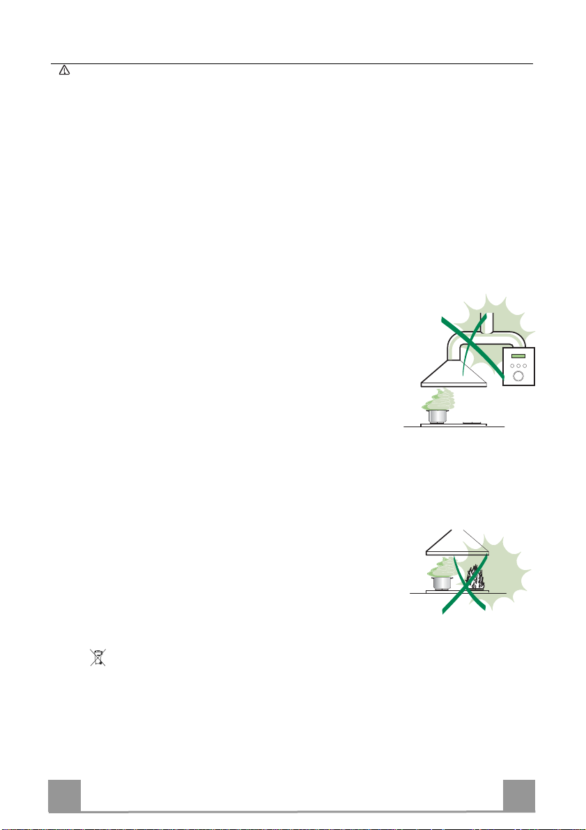
• Do not connect the extractor hood to exhaust ducts carrying combustion fumes (boilers, fireplaces,
etc.).
• If the extractor is used in conjunction with non-electrical appliances (e.g. gas burning appliances), a
sufficient degree of aeration must be guaranteed in the roo m in order to prevent the bac kflow of
exhaust gas. The kitchen must have an opening communicating directly with the open air in order
to guarantee the entry of clean air. When the cooker hood is used in conjunction with appliances
supplied with energy other than electric, the negative pressure in the room must not exceed 0,04
mbar to prevent fumes being drawn back into the room by the cooker hood.
• In the event of damage t o the power cable, it must be replaced by th e manufacturer or by the
technical service department, in order to prevent any risks.
• If the instructions for installation for the gas hob specify a greater distance specified above, this has
to be taken into account. Regulations concerning the discharge of air have to be fulfilled.
“WARNING: Failure to install the screws or fixing device in accordance with these instructions may
result in electrical hazards.”
USE
• The extractor hood has been designed exclusively for domestic use to eliminate kitchen smells.
• Never use the hood for purposes other than for which it has been designed.
• Never leave high naked flames under the hood when it is in operation.
• Adjust the flame intensity to direct it onto the bottom of the pan only, making sure that it does not
engulf the sides.
• Deep fat fryers must be continuously monitored during use: overheated oil can burst into flames.
• Do not flambè under the range hood; risk of fire
• This appliance is not intended for use by persons (including children) with reduced physical, sensory or mental capabilities, or lack of experience and knowledge, unless they have been given supervision or instruction concerning use of the appliance by a person responsible for their safety.
• Children should be supervised to ensure that they do not play with the appliance.
• “ CAUTION: Accessible parts may become hot when used with cooking appliances.”.
MAINTENANCE
• Switch off or unplug the appliance from the mains supply before carrying out any maintenance work.
• Clean and/or replace the Filters after the specified time period (Fire hazard).
• Clean the hood using a damp cloth and a neutral liquid detergent.
or hood is 1200 mm
The symbol on the product or on its packaging indica tes that this product may not be treated as ho usehold waste. Instead it shall
be handed over to the applicable collection point for the recycling of ele ctrical a nd elec tronic equipment. By ensu ring this p roduct is
disposed of correctly, you will help prevent potential negative consequences for the environment and human health, which could
otherwise be caused by inappropriate waste handling of this p roduct. For more detailed information about rec ycling o f this product,
please contact your local city office, your hou sehold waste disposal service or the shop where you purchased the product.
EN
3
3
Page 4

DIMENSIONS and MAIN PARTS
EN
4
4
Page 5

Components
Ref. Q.ty Product Components
1 1 Hood Body, complete with: Controls, Light,
Blower, Filters
2 1 Telescopic Chimney comprising: (Optional)
2.1 1 Upper Section (Optional)
2.2 1 Lower Section (Optional)
10 1 Damper (nr.2 only for 48” model)
13 1 Metal ring (Option only for 48” model)
Ref. Q.ty Installation Components
7.2.1 4 Upper Chimney Section Fixing Brackets (Op-
tional)
11 4 Wall Plugs
11a 2 Wall Plugs SB 12/10
12a 4 Screws 4,2 x 44.45
12c 4 Screws 2,9 x 9,5 (only for 48” model)
Q.ty Documentation
1 Instruction Manual
7.2.1
11
12a
2.1
2
2.2
10
12c
13
11a
1
EN
5
5
Page 6

INSTALLATION
Wall drilling and bracket fixing for Optional Chimney Telescopic
1÷ 2
X
12a
7.2.1
11
7.2.1
11a
1200 mm
313,5
313,5
833 - 1138
406
Wall marking:
• Draw a vertical line on the supporting wall up to the ceiling, or as high as practical, at the
center of the area in which the hood will be installed.
Draw a horizontal line at 1200mm above the hob.
•
• Place bracket 7.2.1 on the wall as shown about 1-2 mm from the ceiling or upper limit (see
the picture).
• Mark the wall at the centers of the holes in the bracket.
• Place bracket 7.2.1 on the wall as shown at X” below the first bracket (X = height of the upper chimney section supplied).
• Mark the wall at the centers of the holes in the bracket.
• Drill ø 8mm holes at all the center points marked.
• Insert the wall plugs 11 in the holes.
• Mark a reference point as indicated at (833 mm for 36” model or 1138 mm for 48” model)
from the vertical reference line and 406 mm above the horizontal reference line.
• Repeat this operation on the other side.
• Drill ø 12 mm holes at all the center points marked.
• Insert the wall plugs 11a in the holes and screw into place.
• Fix the brackets using the 12a screws supplied.
EN
6
6
Page 7

Mounting the hood body
10
• Adjust the two screws Vr of brackets 11a, by just placing them
in position.
• Hook the hood body to the two brackets 11a.
• Remove the filters one at a time, supporting them with one
hand and turning the safety knobs (pull and turn).
• From inside the hood body, tighten the screws Vr to level the
body.
Connections
DUCTED VERSION AIR EXHAUST SYSTEM
When installing the ducted version, connect the hood to the
chimney using a rigid 150 mm duct.
• Install the damper 10 ø 150 mm.
• Fix the duct in position using sufficient pipe clamps (not supplied).
• For rear install ducted version air :
a) From inside the hood, unplug wire attached to blower motor.
b) Turn the hood over and remove the screws holding the ex-
haust blower assembly to the hood.
c) Rotate the blower assembly so that the exhaust collar is fac-
ing out the back of the hood.
d) Replace the screws holding the blower assembly to the hood.
e) Plug the blower motor wire back into the blower motor.
Vr
EN
7
7
Page 8

Vent and Electrical openings
147,6
103,2
33,3
30,2
320,7
30,2
379,4
147,6
103,2
103,2
N.B. Install the Hood kit transition 150mm to 250mm 13 with 4 screws only for upper
ducted version air (Optional not provided ) o nl y for 48” model.
33,3
33,3
200
EN
8
8
Page 9

ELECTRICAL CONNECTION
• Connect the hood to the mains through a two-pole switch having a contact gap of at least 3 mm.
• Remove the grease filters (see paragraph Maintenance) being
sure that the connector of the feeding cable is correctly inserted
in the socket placed on the side of the fan.
Chimney assembly
Upper exhaust Chimney
• Slightly widen the two sides of the upper chimney and hook
them behind the brackets 7.2.1 using the 2 screws 12c
Lower exhaust Chimney
• Slightly widen the two sides of the flue and hook them between the upper flue and the wall, making sure that they are
well seated.
• Remove the filters one at a time, supporting them with one
hand and turning the safety knobs (pull and turn) and fix the
lower part to the hood body from under using the 4 screws 12c
supplied.
EN
2.2
2
2.1
12c
12c
9
9
Page 10

USE
L
M
V
Control board
The cooker hood can be operated as follows:
LIGHT SWITCH L = controls the worktop illumination;
MOTOR SWITCH M = controls the power to the motor and the fan speed:
SPEED SWITCH V = controls the speed
Position 1 = low speed, should be selected when simmering or using only one pan: the noise
level is kept to the minimum.
Position 2 = medium speed, should be selected for normal cooking. This speed offers the best
Position 3 = top speed, should be selected when frying or cooking food with strong odours,
even for a long period.
ratio between air capacity and noise level.
EN
1
10
Page 11

CARE
Grease filters
CLEANING METAL SELF- SUPPORTING GREASE FILTERS
• The filters must be cleaned every 2 months of operation, or
more frequently for particularly heavy usage, and can be
washed in a dishwasher.
• Remove the filters one at a time, supporting them with one
hand and turning the safety knobs (pull and turn).
• Wash the filters, taking care not to bend them. Allow them to
dry before refitting.
• Replace them and fix them using the safety knobs provided
(pull and turn).
Lighting
LIGHT REPLACEMENT
20 W halogen light
• Remove the 2 screws fixing the Lighting support, and pull it
out of from the Hood.
• Extract the lamp from the Support.
• Replace with another of the same type, making sure that the
two pins are properly inserted in the lamp holder socket holes.
• Replace the Support, fixing it in place with the two screws removed as above.
Page 12

4
36006008_05 - 140902
 Loading...