


Contents
1 Instructions 4
1.1 General safety instructions 4
1.2 Manufacturer liability 6
1.3 Appliance purpose 6
1.4 Disposal 6
1.5 Identification plate 7
1.6 This user manual 7
1.7 How to read the user manual 7
2 Description 8
2.1 General description 8
2.2 Control panel 8
2.3 Other parts 9
2.4 Available accessories 10
3 Use 12
3.1 Instructions 12
3.2 First use 13
3.3 Using the accessories 15
3.4 Using the appliance 18
3.5 Turning the appliance off 19
3.6 Cooking Advice 19
4 Cleaning and maintenance 22
4.1 Instructions 22
4.2 Cleaning the appliance 22
4.3 Extraordinary maintenance 26
5 Installation 27
5.1 Safety instructions 27
5.2 Gas connection 29
5.3 Adapting to different types of gas 33
5.4 Electrical connection 36
5.5 Positioning 37
EN
We advise you to read this manual carefully, which contains all the instructions for
maintaining the appliance's aesthetic and functional qualities.
For further information on the product: www.smeg.com
3

Instructions
1 Instructions
1.1 General safety instructions
Risk of personal injury
• Use outdoors only
• During use the appliance and its
accessible parts become very hot.
Keep young children away.
• Keep children under eight years
of age at a safe distance if they
are not constantly supervised.
• Never try to put out a fire or
flames with water: turn off the
appliance and smother the flames
with a fire blanket or other
appropriate cover.
• Have authorised persons carry
out installation and assistance
interventions according to the
standards in force.
• Even if apparently empty, gas
cylinders must always be handled
with care in accordance with the
safety regulations supplied with
the instructions.
• Never use any gas cylinder if
dented or rusty.
• Never store a spare gas cylinder
close to the appliance.
• Never disconnect the gas
cylinder from the appliance while
it is in operation and always
perform any procedure on the gas
cylinder well away from the
appliance.
• Only light the burners with the lid
raised.
• Do not try to repair the appliance
yourself or without the intervention
of authorised persons.
• Do not modify this appliance.
• If the appliance is to be out of use
for some time, close the gas
supply valve.
• In the event of a fault on the
appliance or a malfunction,
contact the aftersales service.
• If the knob becomes stiff to turn,
have the valves checked by an
authorised service centre.
• If the power supply cable is
damaged, contact technical
support immediately and they will
replace it.
• Always keep hold of the lid when
lowering it.
• Observe the thermometer
provided on the lid: when the
reading exceeds 300°c (red
zone) the lid must be raised to
prevent dangerous overheating.
4

Instructions
Risk of damaging the appliance
• In the event of a fault on the
appliance or a malfunction,
contact the aftersales service.
• Do not seat on the appliance.
• Do not use steam jets for cleaning
the appliance.
• Do not obstruct ventilation
openings and heat dispersal slots.
• Never leave the appliance
unattended during cooking
operations where fats or oils could
be released.
• Never leave objects on the
cooking surface.
• Do not use the appliance to heat
rooms for any reason.
For this appliance
• This appliance must be used
outdoors, protected from rain, in
the presence of natural ventilation
which is able to rapidly disperse
any gas leaks or combustion
products.
• Take care not to allow the glass of
the barbecue lid to come into
contact with water while it is still
hot.
• WARNING - this barbecue must
not be used indoors.
• Not for use in marine craft,
caravans or mobile homes.
• Before installation, make sure that
the local gas supply (gas type and
pressure) and the settings of the
domestic appliance are
compatible.
• The settings for this domestic
appliance are shown on the gas
setting label.
• This domestic appliance is not
connected to a device for
extracting combustion products. It
must be installed and connected in
accordance with current
installation regulations. Pay
particular attention to the relevant
requirements regarding ventilation.
EN
• Never use the appliance
outdoors in case of bad weather.
Any contact with water might
seriously damage the appliance
and put its safety at risk.
• Remove any traces of liquid from
the lid (if fitted) before opening.
• Only light the burners with the lid
(if present) raised.
5
Instructions
1.2 Manufacturer liability
The manufacturer declines all
responsibility for damage to persons
or property caused by:
• use of the appliance other than
the one envisaged,
• non-observance of the user
manual provisions,
• tampering with any part of the
appliance,
• use of non-original spare parts.
1.3 Appliance purpose
• This appliance is intended for
cooking food in the home
environment. Every other use is
considered improper.
• This appliance may be used by
children aged at least 8 and by
people of reduced physical and
mental capacity, or lacking in
experience in the use of electrical
appliances, as long they are
supervised or instructed by adults
who are responsible for their
safety.
• The appliance is not designed to
operate with external timers or with
remote-control systems.
1.4 Disposal
This appliance must be
disposed of separately from
other waste (Directives
2002/95/EC, 2002/96/EC,
2003/108/EC). The appliance
does not contain substances in
quantities sufficient to be considered
hazardous to health and the
environment, in accordance with
current European directives.
To dispose of the appliance:
Power voltage
Danger of electrocution
• Disconnect the main power supply.
• Disconnect the power cable from the
electrical system.
• Cut the power supply cable and
remove it along with the plug.
• Consign the appliance to the
appropriate selective collection
centres for electrical and
electronic equipment waste, or
deliver it back to the retailer when
purchasing an equivalent product,
on a one for one basis.
6

Instructions
Our appliances are packed in nonpolluting and recyclable materials.
• Consign the packing materials to
the appropriate selective
collection centres.
Plastic packaging
Danger of suffocation
• Do not leave the packaging or any part
of it unattended.
• Do not let children play with the
packaging plastic bags.
1.5 Identification plate
The identification plate bears the
technical data, serial number and
brand name of the appliance. Do not
remove the identification plate for
any reason.
1.6 This user manual
This user manual is an integral part of
the appliance and must therefore be
kept in its entirety and in an
accessible place for the whole
working life of the appliance.
Read this user manual carefully
before using the appliance.
1.7 How to read the user manual
This user manual uses the following
reading conventions:
Instructions
General information on this user
manual, on safety and final
disposal.
Description
Description of the appliance and its
accessories.
Use
Information on the use of the
appliance and its accessories,
cooking advice.
Cleaning and maintenance
Information for proper cleaning and
maintenance of the appliance.
Installation
Information for the authorised
persons: installation, operation and
inspection.
Safety instructions
Information
EN
Advice
1. Use instruction sequence.
• Single use instruction.
7
2 Description
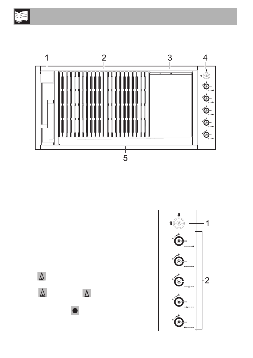
2.1 General description
Description
1 Liquid waste compartment
2 Grills
3 Griddle
2.2 Control panel
1 Battery
The battery supplies the burner ignition
plugs.
2 Burner knobs
Useful for lighting and adjusting the
appliance burners.
Press and turn the knobs anti-clockwise to
the value to light the relative burners.
Turn the knobs to the zone between the
maximum and minimum setting to
adjust the flame.
Return the knobs to the position to turn
off the burners.
4 Control panel
5 Duct
8
Description
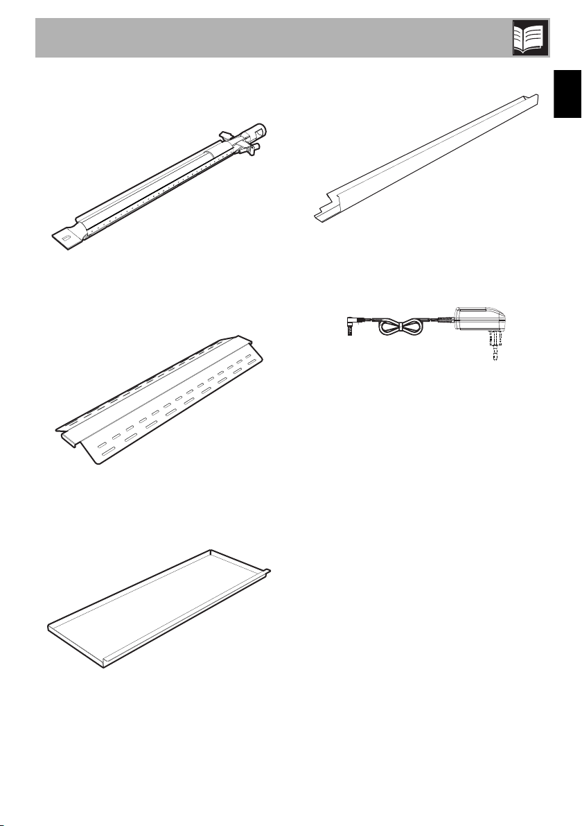
2.3 Other parts
Burners
The fundamental element of the appliance,
these generate the flame for cooking.
Diffusers
Duct
EN
Allows liquids to run off into the liquid waste
compartment.
Mains adapter
Powers the burner igniters. When
connected, the battery is automatically
disconnected.
Useful for making the flame uniform and
improving the type of cooking.
Drip trays
These catch the residue produced by the
food being cooked.
9
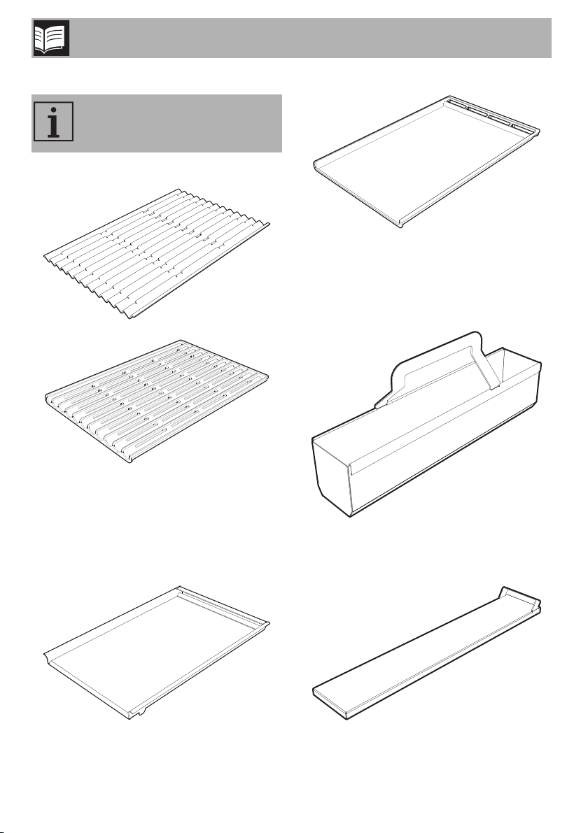
2.4 Available accessories
Some models are not provided
with all accessories.
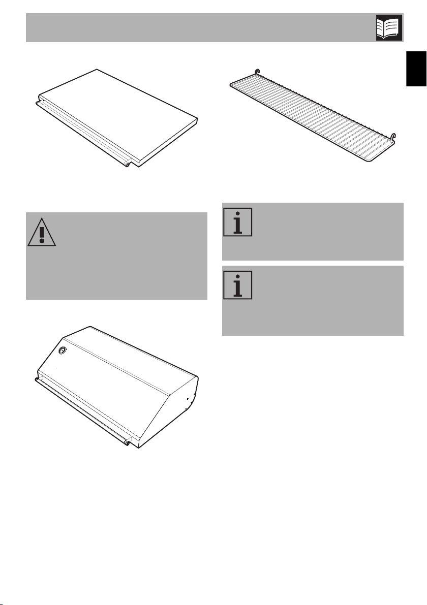
Grills
Description
For direct, uniform cooking of meat, fish and
vegetables, providing light dishes with their
nutritional content intact.
Liquid waste compartment
For rapid cooking of meat, fish and
vegetables directly on the grill, bringing out
their flavour by directly exposing them to the
flame.
Griddle
10
For collecting waste liquids.
Liquid waste compartment cover
For closing the liquid waste compartment
when the appliance is not in use.
Description
Flat lid (on some models only)
For closing the appliance when it is not
being used.
Improper use
Danger of burns or explosions
• THE FLAT LID MUST NOT BE CLOSED
WHEN THE BURNERS ARE
OPERATING.
Lid (on some models only)
Utensil holder (on some models only)
EN
For holding cooking utensils when using the
appliance.
The accessories intended to come
into contact with food are made of
materials that comply with the
provisions of current legislation.
Original supplied and optional
accessories can be requested to
Authorised Assistance Centres.
Use only original accessories
supplied by the manufacturer.
For indirect cooking.
11
Use
3 Use
3.1 Instructions
High temperature during use
Danger of burns
• During use the appliance and its
accessible parts become very hot. Keep
young children away.
• Protect your hands wearing heat
resistant gloves when moving food.
• Do not touch the heating elements inside
the appliance.
• Switch the appliance off immediately
after use.
• Do not pour water directly onto very hot
trays.
• Young children should be supervised to
ensure that they do not play with the
appliance.
• Children must never play with the
appliance.
• The appliance must never be cleaned
by unsupervised children.
• Oils and fat could catch fire if
overheated. Be very careful.
• Always ensure that the burner
components are correctly fitted in place.
Improper use
Risk of damage to surfaces
• Do not rest pans or trays on the lid
(when fitted).
• Do not pour water directly onto very hot
trays.
• Never use the appliance outdoors in
case of bad weather.
• Use wooden or plastic utensils.
• Do not place articles on or against this
appliance.
High temperature during use
Danger of fire or explosion
• DO NOT SPRAY AEROSOLS IN THE
VICINITY OF THIS APPLIANCE WHILE
IT IS IN OPERATION.
• DO NOT USE OR STORE
FLAMMABLE MATERIALS IN OR NEAR
THIS APPLIANCE.
• DO NOT PLACE ARTICLES ON OR
AGAINST THIS APPLIANCE.
• Do not use plastic kitchenware or
containers when cooking food.
• Do not leave the oven unattended
during cooking operations where fats or
oils could be released.
12
Use
3.2 First use
1. Remove any protective film from the
outside or inside of the appliance,
including accessories.
2. Remove any labels (apart from the
technical data plate) from the
accessories and from the cooking
compartments.
3. Remove all the accessories from the
appliance and clean them (see 4
Cleaning and maintenance).
4. Run the burners at full power for 10
minutes before you first use the
appliance to remove any residue from
the manufacturing process.
Diffusers
Before using the appliance, it is necessary
to assemble the diffusers as shown in the
figure below.
Installing the lid (on some models only)
Improper use
Danger of burns
• The lid must always be kept open while
the burners are being lit. It can be
lowered once they have ignited and
must be raised as soon as the
thermometer fitted on it reaches 300°C.
Take care not to obstruct the combustion
gas outlet flue in the back of the lid.
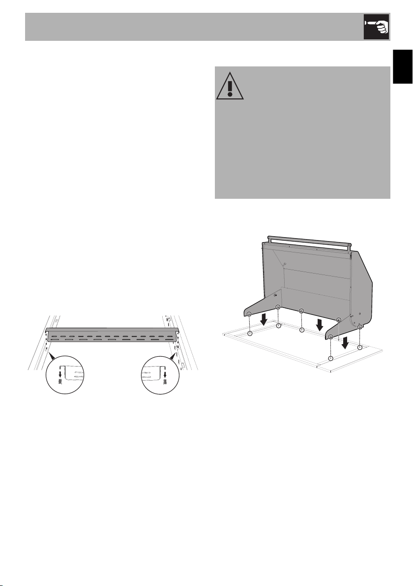
Place the lid in position on the appliance
and attach it with the 6 screws supplied.
EN
13
Use
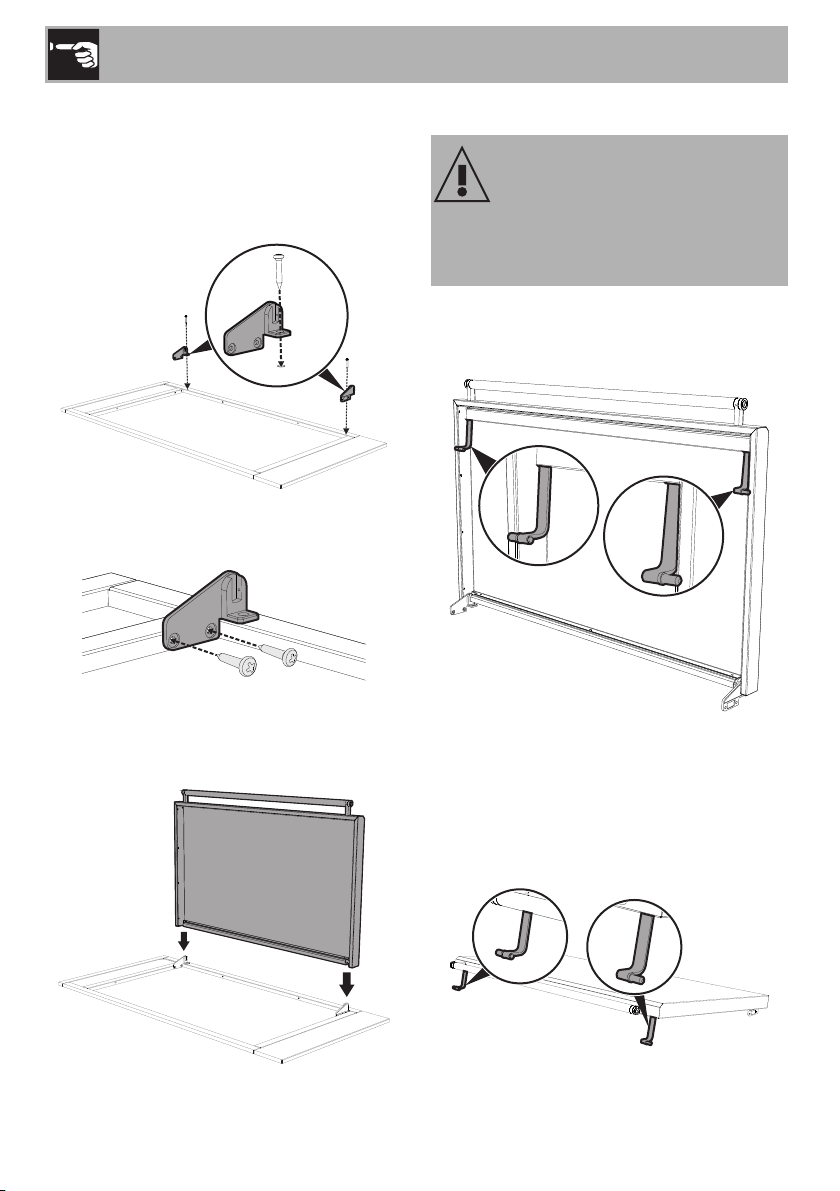
Installing the flat lid (on some models
only)
1. Position the supplied hinges and screw
the 2 supplied screws to the upper part
of the appliance.
2. Fasten the hinges with the 4 supplied
screws.
Flat lid safety legs
Improper use
Danger of burns
• The flat lid must not be closed when the
burners are operating.
To ensure that the user remembers to turn off
the gas before closing the flat lid, two
pivoting safety legs have been fitted.
3. Position the flat lid and fasten the screws
to the upper part of the hinge using an
Allen key to fix it to the appliance.
14
When closing the flat lid the safety legs will
pivot forward and rest against the trim
surface to prevent the flat lid closing. After
ensuring the gas has been turned off, to fully
close the flat lid, the legs need to be rotated
backwards.

Use
3.3 Using the accessories
Clean the grills before using them
for the first time to remove any
residue left by the manufacturing
process.
Positioning the grills and griddle
Incorrect position
Risk of damaging the appliance
• Be very careful when positioning the
grills and the griddle so that they do not
fall into the burner chamber and
damage the burners.
Incorrect position
Risk of fire
• Fats and oils can catch fire if they come
into contact with the hot parts of the
appliance. Always make sure that the
grills and the griddle are inclined
correctly.
The grills and griddle can be arranged in
three configurations but must always be
slightly inclined towards the duct so that the
fats and cooking oils are conveyed into the
liquid waste compartment.
Make sure that the back of the accessories
always rests on the rear support.
EN
Incorrect position
Crushing hazard
• Always follow the instructions when
positioning the accessories.
15

Use
Steel grills and griddle
Configuration A: first position the griddle on
the right hand side, then the central grill and
lastly the left hand side grill so that their
edges fit together.
Configuration B: first position the grills and
make sure that they are as close as possible
to the sides of the cooking area, then
position the griddle so that its edges fit
together with those of the grills at the side.
Configuration C: the grills can be
positioned before or after the griddle.
However, make sure that the edges of the
grills are correctly aligned as shown in
configuration A.
As a rough indication, the steel grills should
be positioned with the slots facing away
from the knobs.
16

Use
Pay particular attention to the mechanical
safety locks that prevent the grills and
griddle from moving accidentally and place
them on the appliance as shown in the
following figures.
Cast iron grills and griddle
The cast iron grills and griddle can be
arranged in any order on the appliance.
The mechanical locks of the grills and the
griddle must always be positioned as
shown in the figure.
As an additional aid to the correct
positioning of the cast iron accessories, also
refer to the “FRONT” marking on their
bottom, which should always be placed
towards the duct.
EN
17

Proceed with cooking only with the
griddle and all grills in position to
avoid danger to the user or
damage to the appliance's
appearance and functionality.
Liquid waste container
It is recommended you empty the liquid
waste container after using the appliance:
1. Remove the liquid waste compartment
cover.
2. Holding the container by its handle, push
it towards the back of the liquid waste
compartment.
Use
3.4 Using the appliance
All the appliance's control and monitoring
devices are located together on the control
panel. The burner controlled by each knob
is shown next to the knob. The appliance is
equipped with an electronic ignition device.
Simply press the knob and turn it anticlockwise to the maximum flame symbol,
until the burner lights. If the burner does not
light in the first 15 seconds, turn the knob to
and wait 60 seconds before trying
again.
After lighting, keep the knob pressed in for
a few seconds to allow the thermocouple to
heat up. The burner may go out when the
knob is released: In this case, the
thermocouple has not heated up sufficiently.
Wait a few moments and repeat the
operation. Keep the knob pressed in
longer.
3. Lift the container upwards.
4. Empty and clean the container.
5. Once you have cleaned the container,
replace it in its compartment and follow
the removal operations above in reverse.
18
Never leave it unattended when in
operation. If you notice that the
flames have gone out, turn the
knobs to IMMEDIATELY and
wait a few minutes before
attempting to ignite the burners
again.

Use
3.5 Turning the appliance off
If the appliance is to be out of use for some
time, close the gas supply valve, unplug the
appliance from the wall socket and remove
the battery.
Before reusing it, check that the gas outlet
holes are not clogged with dust or spider's
webs.
3.6 Cooking Advice
Direct cooking: food cooked
directly on a grill positioned above
a lit burner.
Indirect cooking: food cooked on
a grill positioned adjacent to the lit
burner.
• During indirect cooking the lid (if fitted)
must be left closed and only opened if
the temperature exceeds 300°C. Close
it again after 5 minutes have passed.
• Water should always be poured into the
dripping pans for more succulent
cooking results and to simplify cleaning
of the barbecue after use.
• Always preheat at the minimum setting.
• For processes requiring more powerful
grilling, preheat the burners for 15
minutes.
• Preheat for indirect cooking by igniting
the burner where the food is to be
placed for 5 minutes at the minimum
setting and the other burners at the
maximum setting for 10 minutes.
• During direct cooking (meat or fish), if the
heat is too high and burns the food, turn
the burners down using the knob, or else
move the food.
• During cooking, it is recommended to
remove the liquid waste compartment
cover to allow cooking fumes to escape.
Meat (direct cooking)
The burners must be set to maximum. The
cooking time varies depending on the
thickness of the food and personal taste.
For best results when grilling, brown the
outside at maximum heat then use the knobs
to turn the burners down to a medium /
minimum setting to allow the meat to cook
right through without burning on the outside.
The appearance of flames, when cooking
pork (i.e. fatty foods) in particular, is normal
and is caused by dripping fat. Do not
worry, but move the food being cooked to
another part of the grill.
To allow this, it is best not to fill the whole
grill with food for cooking.
It is recommended to preheat the
burners at maximum power for 510 minutes with the lid (where
fitted) closed, depending on the
thickness of the meat.
EN
19

Use
Meat (indirect cooking)
After preheating with the burners at the
minimum setting and the lid (where fitted)
closed, place the meat on a grill next to the
lit burner. For example, the meat can be
placed on the central grill after the side
burners have been ignited.
The advantage of indirect cooking is that
the heat is less fierce. Start cooking with the
burners on the minimum setting then
gradually turn them up over time.
Naturally, it takes considerably longer than
direct cooking, but excellent results will be
assured.
Cooking information table
Heat
High
Medium-High
Medium
Medium-Low
Low
Temperature
(°C)
230 - 250 Maximum
200 Medium-Maximum
160 - 180 Intermediate
150 Medium-Minimum
110 - 120 Minimum
Burner setting Suitable for
Large pieces of meat or fish such as roasts,
whole chickens, lamb and other particularly
thick/fat cuts are suitable for indirect
cooking.
Vegetables and fish (direct cooking)
Arrange the vegetables and/or fish on the
grill after preheating. Given the nature of
these foods, the knobs should be kept
turned to the minimum setting.
It is recommended to preheat the
burners at minimum power for 15
minutes with the lid (where fitted)
closed.
Preheating before starting cooking.
Direct cooking of thin cuts of meat, fish and vegetables.
Direct cooking of cuts of meat of medium thickness (e.g.
half chicken) and indirect cooking.
Indirect cooking and smoking, or keeping food which
has already been grilled warm.
Smoking and indirect cooking of large pieces of fatty
or delicate foods, or keeping food which has already
been grilled warm.
20

Barbecue cooking
Use
Food
Beef steaks
T-bone steaks
Beef fillet
Chicken joints
Whole chicken
Chops
Pork belly
Whole pork neck
Stuffed roast pork
Pork shank
Spare ribs
Sausages
Leg of lamb
Sliced onion
Sliced aubergine
Whole potatoes
Diced potatoes
Courgettes
Peppers
type
Weight
(Kg)
Preheat. Cooking time Suggestions
Cooking
Direct 0.5 10’ 3’ - 5’
Direct 2 = 4 pcs. 15’ 4’ per side
Direct 1.5 10’ 40’ - 50’
Direct 2 10’ 45’
Indirect 3 10’ 150’
Direct 1 10’ 15’ - 18’
Direct 0.5 10’ 5’ - 7’
Indirect 2.5 10’ 240’
Indirect 2.5 10’ 150’
Indirect 1 10’ 70’
Direct 2 8’ - 10’ 30’ - 40’
Direct 1 10’ 13’ - 15’
Indirect 2.5 10’ 150’ - 180’
Direct 0.6 15’ 10’ - 15’
Direct 0.5 10’ 8’ - 13’
Indirect 1 10’ 90’ - 110’
Indirect 1 10’ 80’ - 90’
Direct 0.5 10’ 15’ - 18’
Direct 3 pcs 10’ 13’ - 15’
EN
Flame at maximum setting
Medium-high flame
Medium-high flame
Minimum flame
Medium-minimum flame
Medium flame
Medium flame
Minimum flame, then increase
Minimum flame, then increase
Minimum flame, then increase
Medium-minimum flame, turn food often
Medium-minimum flame
On stainless-steel griddle
On stainless-steel griddle
Medium flame
Maximum flame
Medium flame
Medium-minimum flame
Medium flame
Prawns
Trout
Small fish (e.g. herring)
Bream
Salmon fillets/steaks
Sea-bass
Pineapple
Polenta slices
Sliced bruschetta
Bread
Direct 0.75 10’ 10’ - 12’
Direct 1 10’ 18’
Direct 0.3 15’ 4’ per side
Indirect 3 10’ 40’
Direct 0.5 10’ 15’
Direct 1 10’ 40’
Direct 0.8 10’ 8’
Direct 1 10’ 4’-5’ per side
Direct 1 5’ 6’-8’ per side
Direct 0.2 5’ 20’ - 25’
Medium-minimum flame
Minimum flame
Maximum flame on stainless steel griddle
Medium-minimum flame
Minimum flame
Minimum flame
Minimum flame
Maximum flame
Medium-minimum flame
Minimum flame
21

Cleaning and maintenance
4 Cleaning and maintenance
4.1 Instructions
Improper use
Risk of damage
• Do not use a steam cleaner to clean the
appliance.
• Do not use cleaning products containing
chlorine, ammonia or bleach on steel
parts or parts with metallic finishes on the
surface (e.g. anodizing, nickel- or
chromium-plating).
• Do not use abrasive or corrosive
detergents on glass parts (e.g. powder
products, stain removers and metallic
sponges).
• Do not use rough or abrasive materials
or sharp metal scrapers.
• Do not wash removable components
such as the grills and griddle in the
dishwasher.
• All previous food residue must always
be removed before cooking.
4.2 Cleaning the appliance
To keep the appliance surfaces in good
condition, they should be cleaned regularly
after use. Let them cool first.
Ordinary daily cleaning
Always use only specific products that do
not contain abrasives or chlorine-based
acids.
Pour the product onto a damp cloth and
wipe the surface, rinse thoroughly and dry
with a soft cloth or a microfibre cloth.
Food stains or residues
Do not use metallic sponges or sharp
scrapers as they will damage the surfaces.
Use ordinary non-abrasive products with
the aid of wooden or plastic utensils if
necessary. Rinse thoroughly and dry with a
soft cloth or a microfibre cloth.
Do not allow residues of sugary foods (such
as jam) to set inside the appliance. If left to
set for too long, they might damage the
enamel lining of the appliance.
Griddle and grills
For best results, clean the griddle and grills
when still lukewarm. Wearing heat-resistant
gloves, dip them in water and then scrub
them with a brass-bristle brush to remove
any food residue. Complete cleaning by
washing the grills with a degreasing nonabrasive detergent and rinse thoroughly.
The continuous contact between
the grills/griddle and the flame
can cause modifications to the
enamel over time in those parts
exposed to heat. This is a
completely natural phenomenon
which has no effect on the
operation of this component.
22

Cleaning and maintenance
Duct
Remove the grills and griddle and then the
diffusers.
Rear support
1. Remove the grills and griddle and then
the diffusers.
2. Lift the rear support upwards to remove it.
3. Clean the support and refit it following
the instructions given above.
Drip trays
EN
1. Turn the duct to the inside of the device
and lift it upwards.
2. Pull the duct to the right to extract it.
3. Clean the duct and refit it following the
instructions given above.
After cooking, carefully remove the drip
trays and pour the fat into a suitable
container; this must then be disposed of in
accordance with local regulations. The oil
or fat produced by cooking meat and fish
must never be poured down drains or sinks,
for example. It must be disposed of
correctly in special containers or delivered
to the collection points provided for by law.
Clean the drip trays with suitable nonabrasive products and put them back in
place.
23

Cleaning and maintenance
Removing the drip trays
Remove the grills and griddle and then the
diffusers.
1. Lift the drip trays up a few centimetres
(one at a time) and move them to the left.
Burners
Check regularly that the burners are igniting
completely and no gas outlet holes are
clogged.
If you notice that a burner is not igniting
completely, blowing it with compressed air
may be sufficient to clear dust or spiders'
webs from the clogged holes. If this is not
sufficient, the burners can be dismantled for
more thorough cleaning, for example by
poking a pin through the clogged holes
and blowing compressed air straight into
the burner.
Removing the burners
Remove the grills and griddle and then the
diffusers.
2. Twist the tray upwards in order to extract
it through the space between the two
burners.
3. Clean the drip trays and refit them
following the instructions given above.
24
Remove the rear support (see “Rear
support”).

Cleaning and maintenance
1. Unscrew retaining screw A.
2. Remove the spring clips from the igniters
and thermocouples.
3. Raise and hold the burner with one hand
and first remove the igniter (1) and then
the thermocouple (2).
4. The burners can then be removed from
their bases in the front of the appliance B
for more thorough cleaning.
5. Refit the burners after cleaning. Fit the
front part in its base B, then screw the
retaining screw A back in.
EN
25

Cleaning and maintenance
4.3 Extraordinary maintenance
Live parts
Danger of electrocution
• Ensure the appliance is switched off to
avoid the possibility of electric shock.
Replacing the battery
1. Turn the battery top 90° clockwise.
2. Run the head of a screwdriver B into slot
D press upwards and take container C
out of housing A.
3. After replacing the battery E, reinsert the
container into its housing, making sure
that slot D is facing inwards.
If the appliance will not be used for
long periods of time, we
recommend removing the battery
from its housing.
26

Installation
5 Installation
5.1 Safety instructions
Heat production during appliance
operation
Risk of fire
• This appliance must not be installed on
any combustible material.
• Check that the support structure has the
required slots.
• Veneers, adhesives or plastic coatings
on adjacent furniture should be
temperature-resistant.
• Keep a minimum side clearance of 100
mm and rear clearance of 250 mm from
any combustible material.
• A vertical clearance of at least 1000 mm
should be maintained between the top of
the cooking surface and any combustible
material.
• If used in a closed environment,
ventilation must be provided for as
explained in chapter 5.5 Positioning.
Gas is highly explosive and can
cause serious injury and damage
to property if allowed to
accumulate and then be ignited.
• Avoid exposure to wind as this will affect
cooking performance and burner
efficiency. If this cannot be avoided
some shielding may be necessary.
• The appliance requires a noncombustible panel under the barbecue
to prevent excessive heat. The panel is to
be placed at 30 mm from the base of the
appliance. There are spacers added to
the bottom of the appliance to prevent
the panel being too close to the base.
Failure to install the noncombustible panel exposes the
user to possible accidental contact
with sharp or hot parts.
Section cut from the work surface
The following operation requires
building and/or carpentry work
and must therefore be carried out
by a competent tradesman.
This appliance must not be installed
on any combustible material.
This appliance can be installed in a support
structure such as an island unit, or in a
worktop with a rear wall:
• If installed in a support structure such as
an island, the appliance must be installed
in the centre.
• If installed in a worktop with rear wall,
ensure that the worktop is made of a
non-combustible material.
EN
27

Installation
Cut an opening in the worktop of the
support structure with the dimensions
indicated in the figure (all measurements
are given in mm).
This appliance requires a front
opening in the support structure.
During cooking, take care not to
obstruct the fat drainage hole in
the front of the appliance. If
necessary, clean it thoroughly with
the aid of a wooden or plastic
utensil.
Hole for running connections
Make a circular hole of minimum 100 mm
to allow electricity and gas connections to
be run. The hole may be made on the righthand side or in the rear of the supporting
structure, always on the right, in
correspondence with the appliance's gas
intake.
(all measurements are expressed in mm).
Side view
28
Rear view

Installation
Alternatively, it is also possible to make a
circular hole of minimum 100 mm diameter
in the non-combustible panel underneath
the appliance.
In this case, we recommend installing the
supplied gas intake extension before
positioning the appliance in the support
structure.
5.2 Gas connection
Gas leak
Danger of explosion
• After carrying out any operation, check
that the tightening torque of gas
connections is between 10 Nm and
15 Nm.
• At the end of the installation, check for
any leaks with a soapy solution, never
with a flame.
• The hoses should not come into contact
with moving parts and should not be
crushed in any way.
• Never use a naked light to check that
gas is flowing from the burners properly,
or to look for gas leaks in the appliance.
• When hooking up the appliance to the
cylinder, use only the fittings and
regulators supplied with the appliance.
These products are also available from
our authorised service centres. Using
any other products can seriously
compromise the safety of the appliance.
• Do not obstruct ventilation openings of
the cylinder compartment.
• If operation is not optimal, DO NOT
ATTEMPT TO REPAIR THE APPLIANCE,
but contact the nearest Authorised
Service Centre.
• The settings for this domestic appliance
are shown on the gas setting label.
• Check cylinders are stamped and
certified to current test date. Check for
damage to seals and hoses, if no
damage is visible, ensure fittings are
adequately tight. Do not use this
appliance if it has damaged or worn
seals.
EN
29

Installation
General information
The operation of the appliance
must be tested by the installer to
confirm all burner flames are blue
in colour, stable and completely
ignite at both high and low flame
settings with no appreciable
yellow tipping, carbon deposition,
lifting, floating, lighting back or
objectionable odour. Test burners
individually and in combination.
This appliance is suitable for installation with
Natural Gas or ULPG (propane/butane).
Refer to “If the gas leak persists, contact the
nearest supplier.” for the relevant burner
pressure and appropriate injector sizes.
When the appliance is to be connected to
Natural Gas then the pressure regulator
supplied must be fitted to the gas inlet. A test
point (for checking the gas pressure) is
supplied either with the regulator or as a
separate fitting in the case of ULPG
(propane) appliances.
This appliance must be installed by an
authorised person in accordance with this
instruction manual, AS/NZS 5601.1 –
Gas installations (installation and pipe
sizing), local gas fitting regulations, local
electrical regulations, local water
regulations, Building Code of Australia and
any other government authority.
LPG: the supplied hose and regulator must
be fitted to the appliance inlet connection.
Gas pressure is 2.75 kPa, the appliance
test point is located on the regulator.
Natural Gas: the supplied regulator must
be fitted to the appliance inlet connection.
Gas pressure must be adjusted to 1.0 kPa
when approximately 50% of the burners are
on high flame; the appliance test point is
located on the regulator. This appliance is
suitable for connection with rigid pipe or
flexible hose. The isolating manual shut-off
valve connection point must be accessible
when the appliance is installed.
Connecting the gas cylinder to the
appliance
Minimum LPG cylinder is 4.5 kg
and the maximum LPG cylinder il
9.0 kg.
Connection of the appliance to the gas
supply must be performed in accordance
with the requirements of AS5601/ AG601.
This product is designed for use only with
LPG gas in suitable cylinders obtainable
from specialised shops. The appliance
comes complete with a rubber hose with
pressure regulator and unions. The pressure
regulator is preset in the factory to ensure
the appliance functions to the highest
standards. The diagram below shows how
to connect the hose supplied to the product
and the gas cylinder.
30

Installation
Australia fitting
New Zealand fitting
The hose must be fitted or replaced
(check its expiration date
periodically) in compliance with
the relevant regulations.
WARNING - In freezing
conditions the pressure of propane
or butane gas can be reduced in
the gas cylinder, causing a lack of
gas pressure. This may affect the
way the barbecue operates.
U.L.P.G. When connecting the appliance
to a portable LPG cylinder, the minimum
capacity of the cylinder should be 4 kg and
the maximum capacity should be 9 kg. Fit
the hose and regulator supplied with the
barbecue and ensure that the nut on the
hose is tightened using a spanner. Do not
use thread tape, as the connection will seal
properly without it. When connecting the
regulator end of the hose to the gas
cylinder, turn the fitting anti-clockwise and
hand tighten only.
DO NOT USE A SPANNER.
When connecting the barbecue to a fixed
LPG supply, it must be installed by a
licensed gas fitter in accordance with
requirements of AS5601 and local gas
authority requirements.
ULPG Hose Dimensions
According to AS1869 Class ‘A’, 10 mm diameter
Length 1000 mm
EN
31

Installation
N.G. When connecting the barbecue to
Natural gas, the barbecue can be
converted from LPG to Natural gas by
fitting the supplied Natural gas injectors
and also a Natural gas conversion kit,
available from your retailer. Natural gas
barbecues must be installed by a licensed
gas fitter by connecting the main gas lines
via copper pipe according to the
requirements of AS5601 and the local gas
authority requirements. Alternatively, you
can have the gas fitter install the gas line
using a “bayonet point” fitting according to
the requirements of AS5601 and local gas
authority requirements. This will allow the
barbecue to be connected and
disconnected by using the special hose
provided in the conversion kit.
Once the barbecue is installed, the gas fitter
can test the connection for leaks by using a
soapy water solutions and test the functions
for safety, ignition and burner operation of
the barbecue before leaving.
Positioning the gas canisters
Example of side canister positioning
Example of rear canister positioning
NG Hose Dimensions
According to AS1869 Class ‘B’, 10 mm diameter
Length 1500 mm
32
Example of canister positioned under the
non-combustible panel

Installation
Connection with a rubber hose
Verify that all following conditions are met:
• Flexible hose must comply with AS/NZS
1869 Class B or D, be of appropriate
internal diameter for the total gas
consumption, be kept as short as
possible (not exceeding 1200mm), must
not be in contact with the floor or any hot
or sharp surfaces.
• The hose assembly must not be subject to
strain, abrasion, kinking or deformations.
• Only use a licensed gasfitter to install this
barbecue and other trades as
applicable; electrician, carpenter,
bricklayer.
• The hose is fixed to the hose connection
with safety clamps;
• Installation with rubber hose must be
carried out so that the length of the
piping does not exceed 1.5 metres.
• No part of the hose is in contact with hot
walls (max. 50 °C);
• The hose is not under traction or tension
and has no kinks or twists;
• The hose is not in contact with sharp
objects or sharp corners;
• If the hose is not perfectly airtight and
leaks gas, do not try to repair it; replace
it with a new hose.
5.3 Adapting to different types of gas
In case of operation with other types of gas,
the burner nozzles must be changed and
the minimum flame adjusted on the gas
taps.
Replacing nozzles
1. Remove the grills and griddle, diffusers
and then the components (see
“Diffusers”).
2. Remove the burners (see “Removing the
burners”).
3. Replace the nozzles using a 7 mm socket
wrench according to the gas to use (see
“If the gas leak persists, contact the
nearest supplier.”).
EN
4. Reposition the burners in their correct
seats.
33

Installation
Adjusting the minimum setting for natural
gas
Light the burner and turn it to the minimum
position. Extract the gas tap knob and turn
the adjustment screw next to the tap rod
(depending on the model) until the correct
minimum flame is achieved (see “Adjusting
the bypass valve” on page 34).
Refit the knob and verify that the burner
flame is stable.
Turn the knob rapidly from the maximum to
the minimum setting: the flame should not go
out. Repeat the operation on all gas taps.
Adjusting the minimum setting for LPG
Tighten the screw located at the side of the
tap rod clockwise all the way.
Following adjustment to a gas
other than the one originally set in
the factory, replace the gas setting
label fixed to the appliance with
the one corresponding to the new
gas. The label is inserted inside the
nozzle pack (where present).
Lubricating the gas taps
Over time the gas taps may become difficult
to turn and get blocked. Clean them
internally and replace the lubrication
grease.
Gas taps should be greased by an
authorised person.
Check for any gas leaks
These operations must be carried
out when the barbecue is
connected for the first time and
every time that it is disconnected
and reconnected to the gas
supply.
Once the barbecue hose has been
connected to the gas supply (LPG),
proceed as follows:
1. Open the gas valve on the LPG canister
(or rotate the tap for the Natural Gas
supply), BUT DO NOT ATTEMPT TO
LIGHT THE BURNERS.
2. With gas pressure in the hose, check for
any leaks on all the connections using a
soap and water solution. Never use a
naked flame to check for leaks.
3. In the event that there is a leak, bubbles
will appear on the faulty connection
where the gas is escaping.
4. Close the gas tap of the gas canister,
tighten the leaking connection and then
repeat the test.
5. If the gas leak persists, contact the
nearest supplier.
34
Never use a flame to detect leaks

Installation
Burner and nozzle characteristics table
1 ULPG 2.75 kPa
Nominal gas consumption (MJ/h)
Injector (1/100 mm) x 5
2 NG 1.0 kPA
Nominal gas consumption (MJ/h)
Injector (1/100 mm) x 5
Adjusting the primary air flow
The operations below must be carried out
for every burner in the appliance:
• Move the screw A of the air regulator
sleeve into the position for the type of
gas to be used, consulting the table
below.
Tighten the regulator screw, making sure
that the distance X is correct.
1 ULPG 2.75 kPa 2 NG 1.0 kPA
X =
10 mm 5 mm
EN
13.5
100
14.4
175
Adjusting the bypass valve
1 ULPG 2.75 kPa 2 NG 1.0 kPA
Turn clockwise until the bypass valve is completely
closed.
Important for Universal LPG
Installers, users and service
personnel when this appliance is to
operated using ULPG, the aeration
shutter must only be fixed to 10mm
opening as shown above.
(When the bypass valve is completely closed) turn
anticlockwise by 1 turn.
35

Installation
5.4 Electrical connection
Power voltage
Danger of electrocution
• Have the electrical connection
performed by authorised persons.
• Use personal protective equipment.
• The appliance must be connected to
earth in compliance with electrical
system safety standards.
• Disconnect the main power supply.
• Do not pull the cable to remove the
plug.
• Use cables withstanding a temperature
of at least 90°C.
• The tightening torque of the screws of
the terminal supply wires must be 1.5 - 2
Nm.
General information
Check the grid characteristics against the
data indicated on the plate.
The identification plate bearing the
technical data, serial number and brand
name is visibly positioned on the appliance.
Do not remove this plate for any reason.
Fixed connection
Fit the power line with an omnipolar circuit
breaker in compliance with installation
regulations.
The circuit breaker should be located near
the appliance and in an easily reachable
position.
Connection with plug and socket
Make sure that the plug and socket are of
the same type. Avoid using adapters and
shunts as these could cause overheating
and a risk of burns.
Testing
At the end of installation, carry out a brief
inspection test. If the appliance fails to
operate, after checking that you have
followed the instructions correctly, unplug
the appliance and contact Technical
Support.
36

Installation
For the installer
• The plug must remain accessible after the
installation is complete. Do not kink or
trap the mains connection cable.
• The appliance must be fitted according
to the installation diagrams.
• Do not attempt to turn or stress the
threaded elbow on the manifold. You risk
damage to this part of the appliance
which may void the manufacturer’s
warranty.
• Before leaving check all connections for
gas leaks with soap and water. DO
NOT use a naked flame for detecting
leaks.
• Ignite all burners individually and
concurrently to ensure correct operation
of the gas valves, burner and ignition.
• Turn the gas knobs to the low position
and observe stability of the flame for
each burner individually and all together.
• In case the appliance fails to operate
correctly after all checks have been
carried out, refer to the Authorised
Assistance Centre in your area.
• When satisfied with the appliance,
please instruct the user on the correct
method of operation.
5.5 Positioning
Heavy appliance
Danger of crush injuries
• Place the appliance into the piece of
furniture with the aid of a second person.
•
Position the barbecue as follows:
• An enclosure with walls on all sides, but
at least one permanent opening at
ground level and no overhead cover.
• Within a partial enclosure that includes
an overhead cover and no more than
two walls.
EN
37

Installation
• Within a partial enclosure that includes
an overhead cover and more than two
walls, the following shall apply: At least
25% of the total wall area is completely
open; At least 30% of the remaining wall
area is open and unrestricted.
• In the case of balconies, at least 20% of
the total of the side, back and front wall
areas shall be and remain open and
unrestricted.
This appliance shall only be used
in an above ground open air
situation with natural ventilation,
without stagnant areas, where gas
leakage and products of
combustion are rapidly dispersed
by wind and natural convection.
Any enclosure in which the
appliance is used shall comply
with one of the above.
• Appliance overall dimensions (mm)
38
Do not use the appliance in
conditions where it is directly
exposed to the elements.
Once the appliance has cooled
down, it must be protected against
the elements in order to avoid
damage to the electrical
components.

Installation
EN
39


 Loading...