

Page 1

Libretto di Istruzioni
Manuel d’Instructio n s
Instructions Manual
Gebruiksaanwijzing
Bedienungsanleitung
Bruksanvisning
Manual de instrucciones
Manual de Instruções
ɋɮɥɩɝɩɟɬɭɝɩ ɪɩ ɸɥɬɪɦɮɛɭɛɱɣɣ
KSE951X - KSE912X – KSE912NX
Page 2

INDICE
CONSIGLI E SUGGERIMENTI ..............................................................................................................................................4
CARATTERISTICHE..............................................................................................................................................................5
INSTALLAZIONE....................................................................................................................................................................6
USO........................................................................................................................................................................................9
MANUTENZIONE.................................................................................................................................................................10
IT
SOMMAIRE
CONSEILS ET SUGGESTIONS ..........................................................................................................................................12
CARACTERISTIQUES.........................................................................................................................................................13
INSTALLATION ....................................................................................................................................................................14
UTILISATION........................................................................................................................................................................17
ENTRETIEN..........................................................................................................................................................................18
INDEX
RECOMMENDATIONS AND SUGGESTIONS....................................................................................................................20
CHARACTERISTICS............................................................................................................................................................21
INSTALLATION ....................................................................................................................................................................22
USE.......................................................................................................................................................................................25
MAINTENANCE....................................................................................................................................................................26
INHOUDSOPGAVE
ADVIEZEN EN SUGGESTIES.............................................................................................................................................28
EIGENSCHAPPEN...............................................................................................................................................................29
INSTALLATIE .......................................................................................................................................................................30
GEBRUIK..............................................................................................................................................................................33
ONDERHOUD ......................................................................................................................................................................34
FR
EN
NL
INHALTSVERZEICHNIS
EMPFEHLUNGEN UND HINWEISE....................................................................................................................................36
CHARAKTERISTIKEN..........................................................................................................................................................37
MONTAGE............................................................................................................................................................................38
BEDIENUNG.........................................................................................................................................................................41
WARTUNG............................................................................................................................................................................42
INNEHÅLL
REKOMMENDATIONER OCH TIPS....................................................................................................................................44
EGENSKAPER.....................................................................................................................................................................45
INSTALLATION ....................................................................................................................................................................46
ANVÄNDING.........................................................................................................................................................................49
UNDERHÅLL........................................................................................................................................................................50
DE
SE
2
2
Page 3

ÍNDICE
CONSEJOS Y SUGERENCIAS...........................................................................................................................................52
CARACTERÍSTICAS............................................................................................................................................................53
INSTALACIÓN......................................................................................................................................................................54
USO......................................................................................................................................................................................57
MANTENIMIENTO................................................................................................................................................................58
ES
ÍNDICE
CONSELHOS E SUGESTÕES............................................................................................................................................60
CARACTERÍSTICAS............................................................................................................................................................61
INSTALAÇÃO.......................................................................................................................................................................62
UTILIZAÇÃO.........................................................................................................................................................................65
MANUTENÇÃO....................................................................................................................................................................66
ɎɅȻɂȻɍɀɆɗ
ɋɈȼȿɌɕ ɂ ɊȿɄɈɆȿɇȾȺɐɂɂ...........................................................................................................................................68
ɏȺɊȺɄɌȿɊɂɋɌɂɄɂ.............................................................................................................................................................69
ɍɋɌȺɇɈȼɄȺ........................................................................................................................................................................70
ɗɄɋɉɅɍȺɌȺɐɂə.................................................................................................................................................................73
ɍɏɈȾ ....................................................................................................................................................................................74
PT
RU
3
3
Page 4
EN
2
RECOMMENDATIONS AND SUGGESTIONS
The Instructio ns for Us e appl y to s everal ver sions of this appli anc e. Acco r
d-
ingly, you may fin d descriptions o f individual features th at do not apply to
your specific appliance.
INSTALLATION
• The manufact urer will not be held liabl e for any damages res ulting from incorrect or impr op er ins ta llat i on.
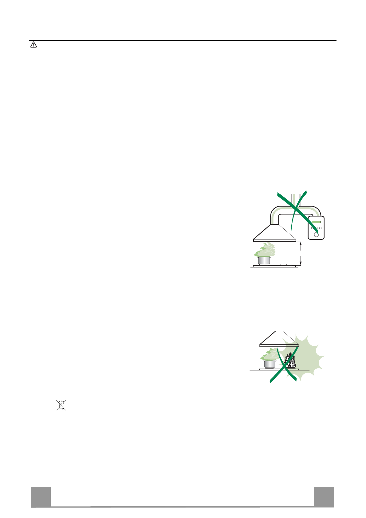
• The minimum safety distance between the cooker top and the extractor
hood is 650 m m (som e m od el s can be insta ll e d at a l ow er height, plea se refer to the paragraphs on working dimensions and installation).
• Check that the mains voltage corresponds to that indicated on the rating
plate fixed to the inside of the hood.
• For Class I a ppliances, check that the domestic power supply guarant ees
adequate earthing.
Connect the extr actor t o the ex haus t flue thr ough a pi pe o f mi nimum diame-
ter 120 mm. The route of the flue must be as short as possible.
• Do not connect the extractor hood to exhaust ducts carrying combustion
fumes (boilers, fireplaces, etc.).
• If the extractor i s used in conjun cti o n with non-elec trical appliances (e.g. gas
burning ap pliances), a s ufficient degree of aeration mu st be guarant eed in
the room in or der to pr event the backflo w of exhaust gas. The kit chen m ust
have an opening communicating directly with the open air in order to
guarantee the entry of clean air.
USE
• The extractor hood has been designed exclusively for domestic use to eliminate kitchen smells.
• Never use the hood for purposes other than for which it has been designed.
• Never lea ve hi gh na ke d fl a me s unde r the ho od when i t is in op er at ion .
• Adjust the flam e in te nsity to dir ect it onto the bo ttom o f t he pan only, maki ng
sure that it does not engulf the sides.
• Deep fat fryers m ust be continu ously monitored during use: ov erheated oil
can burst into flames.
• Do not flambè under the range hood; risk of fire
• Thi s appliance is not intended for use by persons (includi ng children) with
reduced phys ical, sensory or m ental capabilitie s, or lack of experie nce and
knowledge, unl ess th ey have been g iven su pervisi on o r instructi on conce rning use of the appliance by a person responsible for their safety.
• Children should be superv ised to ensure that they do not pl a y with the appliance.
MAINTENANCE
• Switch off or unpl ug the applian ce fr om the m ai ns s up pl y be fo re ca rrying out
any maintenance work.
• Clean and/or replace the Filters after the specified time period (Fire hazard).
• Clean the hood using a damp cloth and a neutral liquid detergent.
650 mm min.
The symbol on the product or on its packaging indicates that this product may not be treated
as household waste. Instead it shall be handed over to the applicable collection point for the
recycli n g of electrical and electro ni c eq uipmen t. By ensuring thi s product i s di s p osed of c or rectly,
you will help prevent potential negative consequences for the environment and human health,
which could otherwise be caused by inappropriate waste handling of this product. For more
detailed information about recycling of this product, please contact your local city office, your
household waste disposal service or the shop where you purchased the product.
20
Page 5

EN
2
CHARACTERISTICS
740
60
300
150
Dimensions
max. 1055
min. 740
Min.
500mm
132
90
433
Min.
650mm
108 259
490
260
Components
Ref. Q.ty Product Components
1 1 Hood Body, complete with: Controls, Light, Blower,
Filters
2 1 Telescopic Chimney comprising:
2.1 1 Upper Section
2.2 1 Lower Section
9 1 Reducer Flange ø 150-120 mm
10 1 Damper
14.1 2 Air Outlet Connection Ex tension
15 1 Air Outlet Connection
Ref. Q.ty Installation Components
7.2.1 2 Upper Chimney Section Fixing Brackets
11 6 Wall Plugs
12a 6 Screws 4,2 x 44,4
12c 6 Screws 2,9 x 9,5
Q.ty Documentation
1 Instruction Manual
15
14.1
12a
7.2.1 11
9
10
2.1
2
2.2
1
12c
11
12a
21
Page 6

EN
2
INSTALLATION
Wall drilling and bracket fixing
1÷2
7.2.1
11
12a
650 min.
116
116
X
320
Wall marking:
• Draw a vertical line on the supporting wall up to the ceiling, or as high as practical, at the
centre of the area in which the hood will be installed.
• Draw a horizontal line at 650 mm above the hob. Place bracket 7.2.1 on the wall as shown
about 1-2 mm from the ceiling or upper limit aligning the centre (notch) with the vertical
reference line.
• Mark the wall at the centres of the holes in t he bracket.
• Place bracket 7.2.1 on the wall as shown at X mm below the first bracket (X = height of the
upper chimney section supplied), aligning the centre (notch) with the vertical line.
• Mark t he wall at the centres of the holes in the bracket.
• Mark a reference poi nt as indicated at 116 mm from the vertical reference line an d 320 mm
above the horizontal reference line.
• Repeat this operation on the other side.
• Drill ø 8 mm holes at all the centre points marked.
• Insert the wall plugs 11 in the holes.
• Fi x the brackets using the 12a (4,2 x 44,4) screws supplied.
• Insert the two scre ws 12a (4,2 x 44,4) supplied in the hood body fixing holes, leaving a gap
of 5-6 mm between the wall and the head of the screw.
22
Page 7

EN
2
Mounting the hood body
• Before attaching the hood body, tighten the two screws Vr located on the hood body mounting points.
• Hook the hood body onto the screws 12a.
• Fully tighten the support screws 12a.
• Adjust the screws Vr to level the hood body.
Connections
DUCTED VERSION AIR EXHAUST SYSTEM
When installing the ducted version, connect the hood to the
chimney using either a flexible or rigid pipe ø 150 or 120mm, the
choice of which is left to the installer.
To install a ø 150 pipe
• To install the dumper 10
• Fix the pipe in position using sufficient pipe clamps (not supplied).
To install a ø 120 pipe
• To install a ø 120 mm air exhaust connectio n, insert the reducer flange 9 on the dumper 10.
• Fix the pipe in position using sufficient pipe clamps (not supplied).
• Remove any activated charcoal filters.
Vr
12a
ø 120ø 150
10
9
10
RECIRCULATION VERSION AIR OUTLET
• Push fit connection 15 onto the hood body outlet.
• Insert the connection extension pieces laterally 14.1 in conn ection 15.
• Make sure that the outlet of the extensio n pieces 14.1 is horizontally and vertically aligned with the chimney outlets. If this
is not the case, adjust the position by either reversing the connection exten sion p ieces 14.1 and th en reasse mble as descri bed
previously.
• Ensure that the activated charcoal filters have been inserted.
14.115
23
Page 8

EN
2
ELECTRICAL CONNECTION
• Connect the hood to the mains through a two-pole switch having a contact gap of at least 3 mm.
• Remove the grease filters (see paragraph Maintenance) being
sure that the connector of the fee ding cable is correctly inserted
in the socket pl aced on the side of the fan.
Chimney assembly
Upper exhaust Chimney
• Slightly widen the two sides of the upper chimney and hook
them behind the brackets 7.2.1, making sure that they are well
seated.
• Secure the sides to th e brackets using the 4 screws 12c (2,9 x
9,5) supplied.
Lower ex haus t Chimney
• Slightly widen the two sides of the chimney and hook them
between the upper chimney and the wall, making sure that they
are well seated.
• Fix the lower part laterally to the hood body using the 2 screws
12c (2,9 x 9,5) supplied.
7.2.1
12c
2.1
2
2.2
12c
24
Page 9

EN
2
USE
Switches the motor on and off at the latest
Control board
Key Function Display
A
select ed speed
B Decreases the suction speed. -
C Increases th e suction speed. -
D By pressing this key it is possible to start the
intensive speed from any previously selected
speed. This speed has been timed at 10 minutes. After that time the system activates automatically the latest selected speed. This function is recommended for cooking condition
where vapours and odours need to be eliminated immediately and quickly.
E By pressing this key it is possible to set up the
motor to a suction speed at 100 m
the intensive speed or the Delay-function this
function ca nnot be activated.
F By pressing this key it is possible to set the
delayed shutdown of the hood to 30 minutes.
This function is suitable for a complete elimination of residu al cooking od ours. Functi oning
only when th e motor is on(n ot during the 24 Hfunction or intensive function)
G By pressing this key for about 2 seconds it is
possible to reset the filter saturation ala rm.
H By pressing this key the intensity of the light-
ing system can be decreased cyclically.
I Switches on/off the lighting system at the
maximum intensity.
L By pressing this key the intensity of the light-
ing system can be increate intensity.
3
/h. During
Indicates the selected speed
HI and the remaining time appear alternately.
The spot d o wn at the right side flashes on ce a
second.
By pressing the key the function is stopped.
24 appears and the spot down at the right side
flashes while the motor is on.
By pressing the key the function is stopped.
The suc tion speed and the rem aining ti me be-
fore the hood shut down appear alternately The
spot down at the right side flashes.
By pressing the key the function is stopped
After 100 working hours a FF appears. Metal
grease filters have to be washed.
After 200 working hours EF appears. Charcoal
filters have to replaced.
Keyboard loc k: it is possible t o jam the keyboard wh en, for example, cleaning the gla ss. The motor and
lights are switched off.
By pressing the D-key (Intensive function) the keyboard block can be activated or deactivated. This function is confirmed by a Beep and by moving motor LEDS on display.
25
Page 10

EN
2
MAINTENANCE
Metal grease filters
Filters can be washed in the dish machine. They need to be
wash e d wh e n FF-sign appears on the d isplay or in any case every
2 months, or even more frequently in case of particularly intensive use of the hood.
Alarm reset
• Press the G-key for at least 2 seconds.
Cleaning
• Remove the filters one at a time holding them up with one
hand and pulling the handle downwards with the other hand at
the same time.
• Wash the filters. Pay attention not to bend them. Make sure
that filters are completely dry before putting them into their
seat. (a possible modification of the filter surface doesn’t influence its efficiency).
• Place the filters again into their seats and make sure that the
handle of the filter remains outside.
26
Page 11

EN
2
Charcoal filter (recycling version
This filter cannot be washed or regenerated. It has to be replaced when the EF appears on the
display or at least once every 4 months.
Activation of the alarm signal
• In the recycling version hoods the filter saturation alarm has to be activated during the installation or later.
• Switch off the hood and the lights.
• Press the E-key for about 5 seconds until the LED on the display start to move.
• Press the B-key w ithin 5 seconds until a confirmation of the activated state of filter satura-
tion alarm on the display appears:
• 2 flashings on EF - charcoal filter saturation alarm ACTIVATED
• 1 flashing on EF - charcoal filter saturation alarm DEACTIVATED.
SUBSTITUTION OF THE CHARCOAL FILTER
Alarm reset
• Switch off the motor and the lighting system.
• Press the G-key for at least 2 seconds.
Substitution of the filter
• Remove the metal grease filters.
• Re move the charcoal filter as indicated in the picture.
• Place the filter again into its seat.
• Place again the metal grease filters into their place.
)
Lighting
LIGHT REPLACEMENT
20 W halogen light.
• Remove the 2 screws fixing the Lighting support, and pull it
out of from the Hood.
• Extract the lamp from the Support.
• Replace with another of the same type, making sure that the
two pins are properly inserted in the lamp holder socket holes.
• Refit the Support, fixing it in place with the two screws removed as above.
27
 Loading...