

Page 1
Libretto di Istruzioni
Instructions Manual
Manuel d’Instructions
Bedienungsanleitung
Manual de instrucciones
Manual de Instruções
Gebruiksaanwijzing
Bruksanvisning
Руководство
по эксплуатации
Page 2

Page 3
WARNING!
b)
The hood is supplied with two supports/hooks (a)
c)
Remove the anti-grease filters, put the hood on
and level by means of the adjusting screw
• Read the instructions carefully before installing and/or using the hood.
• Before connecting, make sure that the mains voltage corresponds to the voltage on
the rating plate inside the hood. (see fig. 7)
• Once you remove the appliance from its packaging make sure it is intact. If the
product is damaged, do not use it and contact the Smeg assistance network.
It is recommended that a qualified technician performs installation and adjustment
•
operations
• The minimum distance between the cooker and the lower part of the hood must be
750mm for gas cookers and 650 mm for electric cookers.
• Before carrying out any kind of maintenance or cleaning, disconnect the hood from
the mains supply.
• Inspect and clean the filters thoroughly and in accordance with the intervals
suggested by the manufacturer.
• Do not cook or fry in a way that could result in flames being sucked into the hood and
causing a fire.
• The hood surface can be cleaned with a damp cloth and a non-bleach liquid
detergent.
• Make sure the room is properly ventilated when using the hood and other gas
appliances at the same time.
• Comply with the regulations on air discharge when operating the hood.
• The extracted air must not be routed into a duct used to discharge fumes of gas-
operated appliances.
• This appliance must not be used by children without an adult supervision or
by disabled people without assistance.
• THE MANUFACTURER CANNOT BE HELD RESPONSIBLE IF THE ABOVE
INSTRUCTIONS ARE NOT FOLLOWED.
.
OPERATION
This appliance has been designed to work as a DUCTING hood (evacuation of the
air) or RECYCLING hood (recycling of the filtered air).
• DUCTED MODE: In order to use the hood in the ducted mode, connect the motor
intake, by means of a suitable ducting hose not less than 120mm diameter, directly to
the external fumes outlet.
Note:Remove any carbon filters.
• RECIRCULATION MODE: If it is not possible to discharge fumes outside, the hood
can be used to filter and recycle the air. This way, air and fumes are filtered by the
anti-odour carbon filters and recirculated through the aerating grids on the sides of
chimney.
EN 01
Page 4
INSTALLATION INSTRUCTIONS:
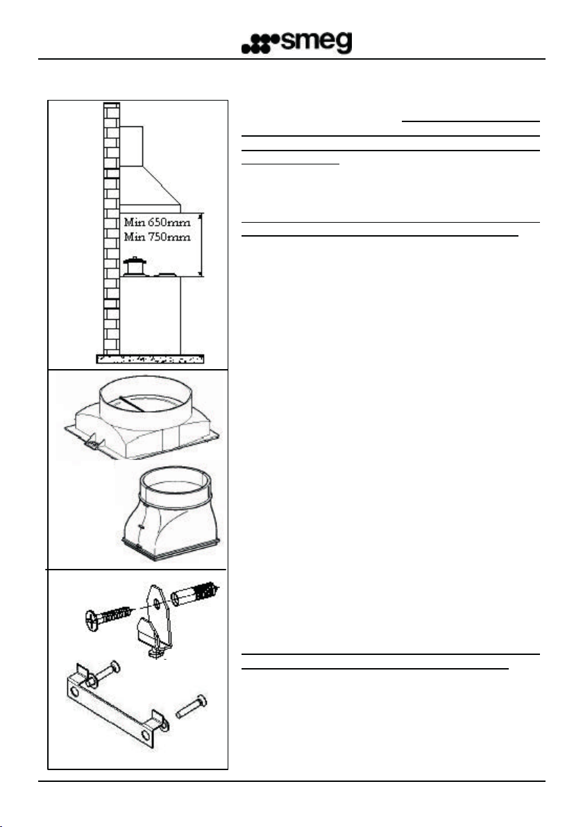
Fig.1
Fig.2
Type 1
Type 2
The hood is supplied with all the necessary
accessories for installation. The minimum distance
between the cooker and the lower part of the hood
must be 750 mm for gas cookers and 650 mm for
electric cookers (Fig. 1). The hood is supplied with a
motor intake (Fig 2). If it has not been assembled by
the manufacturer, you can assemble it using the
supplied screws (for type 1) or pushing (for type 2)
If the motor intake is equipped with a non-return
valve, make sure it opens and closes perfectly.
The following instructions will assist installation:
a) The hood should be centred with respect to the
cooker.
b) The hood is supplied with two supports/hooks (a)
(Fig 3) or bracket (b) that need to be fixed to the
wall by means of wall anchors . The L1 holes for
these supports are on the back of the hood (fig.
4)
c) Remove the anti-grease filters, put the hood on
the wall and mark the position of the holes for the
supports/hooks.
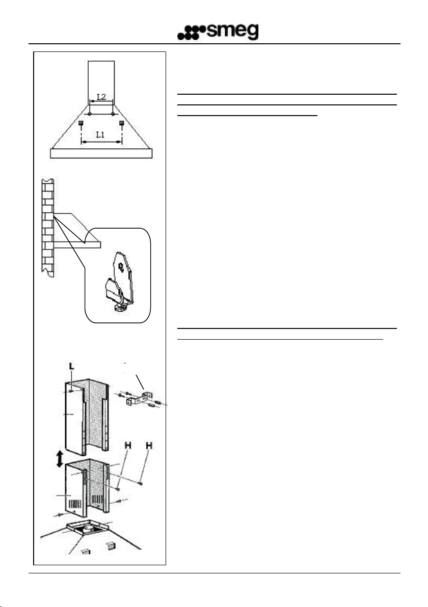
d) Drill the two previously marked holes after
removing the hood from the wall.
e) Fix the two supports/hooks to the wall.
f) Mark the L2 holes on the wall to fix the hood
safely. (fig. 4) Drill and put the anchors in the
holes.
g) Hang the hood on to the supports/hooks (fig. 5)
and level by means of the adjusting screw
(
).
fig.3
l) Fix the hood safe by tightening both wall anchors.
Fig.3
(a)
Hood levelling screw
(b)
Ducted mode or Recirculation mode installation:
Ducted mode:
In the ducted mode, connect the motor outlet to the
fumes outlet duct not less than 120mm diameter.
Warning: if the hood is equipped with an active
carbon filter, it must be removed (see page 7)
EN 02
Page 5
B
minutes before starting cooking and keep it on for at least 15 minutes after finishing
A
B
Fig.4
Fig.5
Fig.6
Recirculation mode:
Leave the motor intake free. Install the active carbon
filters as shown in page 7.
Warning: if the hood is not supplied with an active
carbon filter, it is necessary to buy it separately and
assemble it before using the hood.
m) Chimneyassembly:
Adjust the two telescopic chimneys to the required
length (fig. 6).
Block the chimneys by tightening the two H screws .
Place the chimneys group on the top side of the hood
carefully. Put the chimney bracket K on the
chimney (fig. 6). Mark the holes on the wall for fixing
the chimney bracket to the wall.
Remove the chimney set, drill and fix the support
racket to the wall by means of wall anchors. . Put the
chimney group back in place and fix it to the hood with
the Z screws and to the chimney bracket with the L
screws as shown in figure 6.
ELECTRICAL CONNECTION
It is recommended that all electrical connection
operations are performed by a qualified technician.
The appliance is supplied WITHOUT A PLUG. It is
K
B
therefore necessary to fix a plug to the wire. The plug
and fuse must be in accordance with the rating plate
inside the hood. Then connect it to a nearby, easily
reachable socket in accordance with the rules in
force.
In the case of a direct connection to the mains supply,
it is necessary to put a switched spur between the
appliance and the mains supply. The switch must be
suitable for the load, compliant with the rules in force
and must have a minimum contact opening of not less
than 3mm.
Z
Z
EN 03
Page 6
OPERATING INSTRUCTIONS:
A
B
CONTROL PANEL:
In order to achieve the best performance, it is recommended to start the hood a few
minutes before starting cooking and keep it on for at least 15 minutes after finishing
cooking or after all fumes and odours have disappeared.
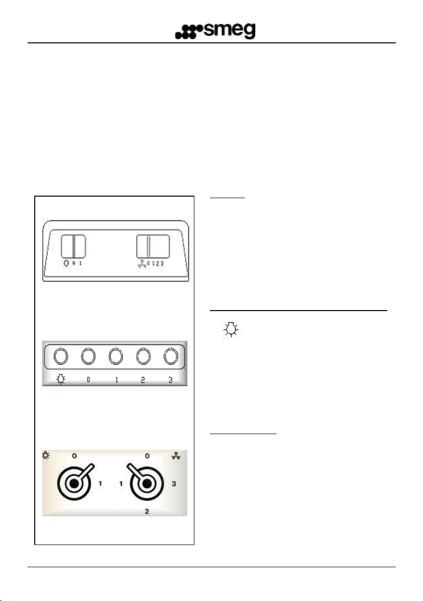
To start the hood, identify your type of control panel and follow the instructions:
SLIDER:
- Key (A) to turn on/off the hood’s light.
- Four-position Cursor (B):
0: Off
1/2/3: On/Speed adjustment
(A) (B)
ELECTROMECHANICAL PUSHBUTTONS:
Light ON/OFF Button
Motor OFF button
On/speed adjustment button
:
(A) to turn on/off
(B):
(A) (B)
WITH KNOBS
- Two-position Knob
the light (0-1)
- Four-position Knob
0 Motor OFF
1-2-3 Speed adjustment
EN 04
Page 7
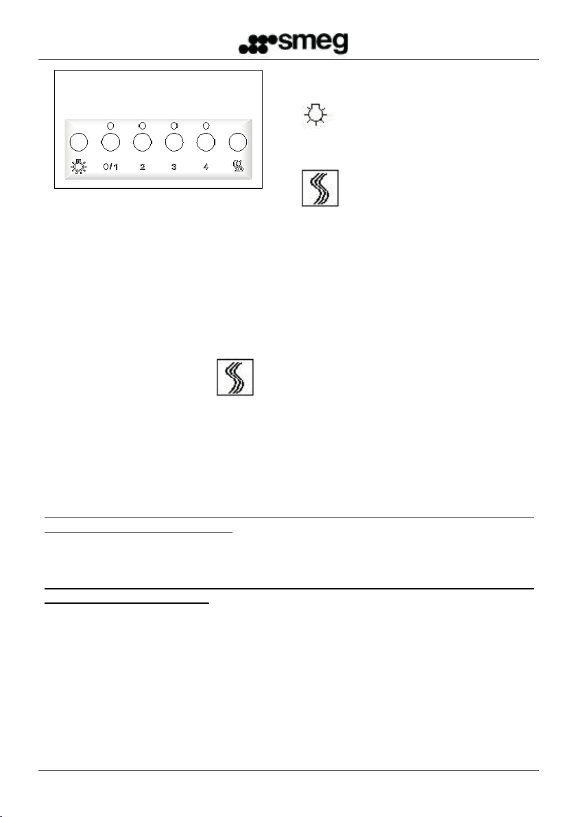
ELECTRONIC PUSHBUTTONS:
It
Lights ON/OFF
Filters reset button
OPTIONAL FUNCTIONS:
- AUTO POWER-OFF TIMER: Pushing one of the speed adjustment buttons (2-3-4)
twice, you will activate the “Auto power-off timer” function that turns the motor and light off
10 mins. The activation of such function is signalled by the blinking LED
after
OFF/1 speed
Speed adjustment
above the pressed button.
- FILTERS CLEANING WARNING: When all the 4 LEDs blink at the same time
programmed to happen every 100h of operation)
clean/replace the filters
.
, the user is required to
(which is
Pressing the Reset button the 100h count will start again
Note: Pressing the reset button accidentally before the end of the 100h
cycle does not reset the filters cleaning memory
It is recommended that grease filters are cleaned every 100h and active
carbon filters are replaced every 200h.
CLEANING AND MAINTENANCE:
Before performing any cleaning and/or maintenance operation always disconnect
the hood from the mains supply.
Regular cleaning will ensure a good performance and extend the working life of the hood.
Special attention should be given to the grease filters and carbon filters (for recycling
hoods only).
Note: An excess of grease in the filter, as well as affecting the performance of the
hood, can also be a fire risk.
EXTERNAL CLEANING:
External and internal cleaning of the hood should be performed with a damp cloth and a
non-bleach liquid detergent, absolutely avoiding solvents or abrasive substances.
is advisable to use specific products, following their instructions. When cleaning the steel
of the hood, we suggest rubbing in the same direction as the grain.
EN 05
Page 8

METAL FILTERS CLEANING:
recommended they are replaced at least once every
shown in fig. A and then remove them from their
Special attention should be reserved to the metal
grease filters. An excess of grease in the filter, as well
as affecting the performance of the hood, can also be
a fire risk. To avert fires, the filters must be cleaned
regularly at least once a month or more frequently, in
the case of a heavy use of the appliance.
According to your hood’s model, remove one filter at a
time as shown in these pictures. Wash the filters
thoroughly with a non-bleach detergent, either by
hand or machine. Re-assemble the filters, making
sure that the handle faces the outside of the hood
CARBON FILTERS REPLACEMENT: (For recirculated version only)
The carbon filters can only retain odours for a limited
period of time. They cannot be washed, therefore, it is
six months or more frequently in the case of a heavy
use of the appliance.
Before starting, make sure the hood is disconnected
Fig.A
from the mains supply.
To reach the active carbon filters, it is necessary to
remove the metal filters as shown above. Use the
pictures to find the carbon filter kit of your hood.
Round filter: simply rotate the filters 90 degrees as
seats.
Spring-held cartridge filter (fig. B): press enough to
overcome the spring’s resistance and remove the
filter.
Cartridge filter with bracket and threaded knob (fig.
C): unscrew the knob, remove the blocking racket and
then remove the active carbon filter.
Fig.B
Re-assemble the carbon and metal filters performing
the above mentioned operations backwards.
Note: only for the electronic controlled hood, reset the
filters cleaning warning by pressing the Filter reset
button.
Fig.C
EN 06
Page 9

LIGHTS REPLACEMENT:
neon tube
To reach the
The hood packaging includes, together with this operating and maintenance booklet, the
(a)
Before performing any cleaning and/or
maintenance operation, disconnect the hood
from the mains supply.
According to the model, the hood can be equipped
with different kind of lighting such as incandescent,
halogen and neon lamps.
a) Incandescent lamps: E14 – 40W 230V lamps.
To replace them, remove the transparent fixture
from the control panel, unscrew the lamp and
screw in the new one.
(c)
(b)
b) Halogen lamps: G4, 20W - 12V lamps . To
replace the lamp, use a screwdriver to remove
the glass-supporting ring. Then remove the old
lamp and insert the new one.
Put the glass back, securing it with the ring.
c) Biax neon lamps: G23 11W lamp. Once the
fixture has been removed, remove the biax lamp
from its seat and support.
Put a new lamp in, performing the same
operations backwards.
d) Neon lamp: 15/18W
neon tube, unscrew the glass framework screws.
Rotate the tube 90 degrees and remove the neon
lamp. Install the new neon tube and put the glass
framework back.
.
(d)
EN 07
Page 10

WARRANTY AND TECHNICAL ASSISTANCE
SERVICE
The hood packaging includes, together with this operating and maintenance booklet, the
Smeg Warranty Booklet. Please read the Smeg Warranty Booklet for complete
information about the warranty (N.B. bulbs and filters are not covered by your warranty).
In the case of failure, please call
Fig.7
and provide the following data:
•
The model indicated inside the hood (fig. 7)
Your full address
•
•
Your telephone number
•
Information on the kind of failure
Customer Service
0870 9909907
EN 08
Page 11

This appliance is marked according to the European directive 2002/96/EC on Waste
Electrical and Electronic Equipment (WEEE).
By ensuring this product is disposed of correctly, you will help prevent potential
negative consequences for the environment and human health, which could otherwise
be caused by inappropriate waste handling of this product.
The symbol
indicates that this appliance may not be
treated as household waste. Instead it shall be handed over to the applicable
collection point for the recycling of electrical and electronic equipment.
Disposal must be carried out in accordance with local environmental regulations for
waste disposal.
For more detailed information about treatment, recovery and recycling of this product,
please contact your local city office, your household waste disposal service or the
shop where you purchased the product.
on the product, or on the documents accompanying the product,
EN 09
Page 12

Cod.1710568
Page 13

KCI19A
KCI19P
Page 14

Installazione
Montaggio dei corrimano
I corrimano in dotazione sono
parte integrante del prodotto ed è
necessario fissarli all’apparecchio
prima di installarlo.
Sulle parti laterali della cappa sono
presenti 4 fori filettati utili per il montaggio
dei corrimano.
Per ogni foro filettato, utilizzare un
cacciavite con punta a taglio per avvitare i
supporti corrimano in dotazione.
Posizionare i corrimano sui supporti. Per
ogni corrimano, cercare di infilare
parallelamente i due supporti sugli scassi
del corrimano.
Con una chiave a brugola di 2 mm,
avvitare le viti senza testa a cava
esagonale negli appositi fori di fissaggio
per fissare i corrimano ai supporti.
Per ragioni estetiche, prestare
attenzione a posizionare i
corrimano con i fori di fissaggio
rivolti verso il basso.
IT
1
Page 15

Handrails assembly
The handrails provided are an
integral part of the product,
therefore necessary to fix
before installing the unit.
On the lateral parts
threaded holes useful for mounting
the handrail.
For each threaded hole, use a
flathead screwdriver to screw the
handrail supports supplied.
of the hood
For aesthetic reasons, be
careful to position the
handrail with the fixing
holes facing downwards.
Installation
Place the handrail on the supports;
for every handrail try to insert the
two supports parallelly into the
notches of the handrail.
With a 2 mm hex key, tighten the
hexagon socket grub screws in the
are 4
appropriate holes to attach the
handrail to the supports.
EN
2
Page 16

Montage de la main courante
Sur les parties latérales de la hotte
se trouvent 4 trous filetés pour le
montage de la main courante.
Pour chaque trou fileté, utiliser in
tournevis plat pour visser les
supports de la main courante
fournie
Les mains courantes en dotation
font partie intégrante du produit
et elles doivent être fixées à
l’appareil avant de l’installer.
Installation
Positionner les mains courantes sur
les supports. Pour chaque main
courante, enfiler parallèlement les
deux supports sur les orifices de la
main courante.
Avec une clé Allen de 2 mm, visser
les vis Allen sans tête dans les trous
de fixation pour fixer les mainscourantes aux supports.
Pour des raisons esthétiques
faire attention de positionner les
mains-courantes avec les trous
de fixation tournés vers le bas.
FR
3
Page 17

Montage des Handlaufs
Die in der Ausstattung
enthaltenen Handläufe sind
Teil des Produkts und müssen
vor der Installation am Gerät
angebracht werden.
An den Seiten der Abzugshaube
befinden sich 4 Bohrungen für die
Montage des Handlaufs.
Um die Halterungen des Handlaufs
mithilfe der Bohrungen
anzubringen, muss ein
Schlitzschraubenzieher verwendet
werden.
Installation
Die Handläufe an den Halterungen
positionieren. Dabei müssen die
beiden Halterungen parallel in die
Einkerbungen der Handläufe
eingeführt werden.
Um die Handläufe zu befestigen,
die Gewindestifte in die
entsprechenden Löcher einsetzen
und mit einem Inbusschlüssel 2
mm festziehen.
Für ein bessere Optik muss darauf
geachtet werden, die Handläufe so
anbringen, dass die Bohrungen zur
Befestigung nach unten zeigen.
DE
4
Page 18

Montaje de los pasamano
The handrails provided are an
integral part of the product,
therefore necessary to fix
before installing the unit.
Las partes laterales de la capa
cuentan con 4 agujeros roscados
útiles para el montaje de los
pasamanos. Para cada agujero
roscado, use un destornillador con
punta de corte para atornillar los
soportes pasamanos en dotación.
Instalación
Coloque los pasamanos sobre los
soportes. Para cada pasamano,
busque introducir paralelamente
los dos soportes sobre los
desfondes del pasamano.
Con una llave Allen de 2 mm,
enrosque los tornillos sin cabeza
de ranura hexagonal en sus
agujeros de fijación para fijar los
pasamanos a los soportes.
Por razones estéticas, preste
atención a colocar los
pasamanos con los agujeros de
fijación dirigidos hacia abajo.
ES
5
Page 19

Montagem dos corrimões
Nas partes laterais da estrutura, há
chave de fenda com ponta de corte
para parafusar os suportes do
corrimão fornecidos
Os corrimões fornecidos são
parte integrante do produto e é
necessário fixá-los no dispositivo
antes de instalá-lo.
4 furos roscados úteis para a
montagem do corrimão.
Para cada furo roscado, usar uma
Instalação
Posicionar o corrimão nos suportes.
Para cada corrimão, tentar encaixar
paralelamente os dois suportes nas
ranhuras do corrimão.
Com uma chave allen de 2 mm,
apertar os parafusos sem cabeça com
sextavado interno nos furos de fixação
adequados, a fim de fixar o corrimão
nos
suportes.
Por razões estéticas, colocar o
corrimão com os furos de
fixação virados para baixo.
PT
6
Page 20

Installatie
De rails installeren
On the lateral parts of the hood are 4
threaded holes useful for mounting
the handrail.
De meegeleverde rails zijn een
onderdeel van het product en
moeten voor de installatie aan
het apparaat worden
bevestigd.
For each threaded hole, use a
flathead screwdriver to screw the
handrail supports supplied.
Place the handrail on the supports;
for every handrail try to insert the
two supports parallelly into the
notches of the handrail.
Draai met een 2 mm inbussleutel
de koploze schroeven aan in de
speciale openingen en bevestig de
rails aan de steunen.
Voor een beter aanzicht, zorg
ervoor dat u de rail zo aanbrengt
dat de schroefdraadopeningen
naar beneden zijn gericht.
NL
7
Page 21

Installation
Montering av handräcket
De medföljande handräckena
är en integrerande del av
produkten och det är
nödvändigt att fästa dem på
anordningen innan den
installeras
På kåpans sidor återfinns 4 gängade
hål, som ska användas för
monteringen av handräcket.
Använd en bladskruvmejsel för varje
gängat hål,för att fästa de
medföljande hållarna för
handräcket.
Placera handräcket med hållarna.
Försök, att för varje handräcke
föra in de två hållarna parallellt i
handräckets skåror.
Skruva fast insexskruvarna i de
därför avsedda hålen, med en
insexnyckel på 2mm, för att fästa
handräcket i hållarna.
Var uppmärksam, av estetiska
skäl, att placera handräcket
med hålen vända nedåt.
SV
8
Page 22

Монтаж перил
Входящие в комплект поставки
перила являются
неотъемлемой частью изделия
и перед установкой их
необходимо зафиксировать на
оборудовании
На боковых частях вытяжки
имеется 4 резьбовых отверстия,
предназначенных для монтажа
перил.
Для каждого резьбового
отверстия использовать отвертку с
острым концом, чтобы привинтить
входящие в комплект поставки
суппорты перил/
Монтаж
Place the handrail on the supports;
for every handrail try to insert the
two supports parallelly into the
notches of the handrail.
С помощью ключашестигранника 2 мм навинтить
винты без полой шестигранной
головки в специальные
крепежные отверстия, чтобы
прикрепить перила к суппортам/.
По соображениям эстетического
характера, следить за тем, чтобы
крепежные отверстия перил были
обращены вниз.
RU
9
Page 23

Cod. 1700569
 Loading...