

Page 1

Instruction manual
COOKER 90 X 60
60 X 60
60 X 50
Page 2

3 – 31
Thank you for choosing our product.
We advise you to read this manual carefully. It contains all necessary instructions for maintaining
unaltered the appearance and functional qualities of the cooker.
Page 3
Contents
E
_
4
e
1 INSTRUCTIONS FOR SAFE AND PROPER US
_______________________________
2 INSTALLATION OF THE APPLIANCE__________________________________________6
3 ADAPTATION TO DIFFERENT TYPES OF GAS _________________________________9
4 FINAL OPERATIONS______________________________________________________14
5 DESCRIPTION OF CONTROL PANEL ________________________________________16
6 USE OF THE COOKING HOB _______________________________________________18
7 USE OF THE OVEN_______________________________________________________21
8 ELECTRONIC PROGRAMMER (ONLY ON EQUIPPED MODELS) __________________25
9 DIGITAL TIMER (CERTAIN MODELS ONLY)___________________________________27
10 ANALOGUE CLOCK (ONLY ON EQUIPPED MODELS) _________________________27
11 CLEANING AND MAINTENANCE___________________________________________28
12 EXTRAORDINARY MAINTENANCE_________________________________________30
THESE INSTRUCTIONS ARE VALID ONLY FOR END USER COUNTRIES WHOSE IDENTIFICATION
SYMBOLS APPEAR ON THE COVER OF THIS MANUAL.
INSTRUCTIONS FOR THE INSTALLER: these are for the qualified technician who must carry out a
suitable check of the gas system, install the appliance, set it functioning and carry out an inspection te st.
INSTRUCTIONS FOR THE USER: these contain user advice, description of the commands and th
correct procedures for cleaning and maintenance of the appliance.
3
Page 4
1 INSTRUCTIONS FOR SAFE AND PROPER USE
THIS MANUAL IS AN INTEGRAL PART OF THE APPLIANCE AND THEREFORE MUST BE KEPT
IN ITS ENTIRETY AND IN AN ACCESSIBLE PLACE FOR THE WHOLE WORKING LIFE OF THE
COOKER. WE ADVISE READING THIS MANUAL AND ALL THE INSTRUCTIONS THEREIN
BEFORE USING THE COOKER. ALSO KEEP THE SERIES OF NOZZLES SUPPLIED.
INSTALLATION MUST BE CARRIED OUT BY QUALIFIED PERSONNEL IN ACCORDANCE WITH
THE REGULATIONS IN FORCE. THIS APPLIANCE IS INTENDED FOR DOMESTIC USES AND
CONFORMS TO CURRENT REGULATIONS IN FORCE. THE APPLIANCE HAS BEEN BUILT TO
CARRY OUT THE FOLLOWING FUNCTIONS: COOKING AND HEATING-UP OF FOOD. ALL
OTHER USES ARE CONSIDERED IMPROPER.
THE MANUFACTURER DECLINES ALL RESPONSIBILITY FOR IMPROPER USE.
DO NOT LEAVE THE PACKING IN THE HOME ENVIRONMENT. SEPARATE THE VARIOUS
WASTE MATERIALS AND TAKE THEM TO THE NEAREST SPECIAL GARBAGE COLLECTION
CENTRE.
IT IS OBLIGATORY FOR THE ELECTRICAL SYSTEM TO BE GROUNDED ACCORDING TO THE
METHODS REQUIRED BY SAFETY RULES.
Introduction
WHEN LINKING UP TO MAINS BY PLUG AND SOCKET, MAKE SURE THAT BOTH ARE
COMPATIBLE AND CONNECT BY MEANS OF A POWER CABLE COMPLYING WITH APPLICABLE
REGULATIONS.
THE SOCKET MUST BE ACCESSIBLE AFTER THE APPLIANCE HAS BEEN BUILT IN.
NEVER UNPLUG BY PULLING ON THE CABLE.
IMMEDIATELY AFTER INSTALLATION CARRY OUT A BRIEF INSPECTION TEST OF THE
APPLIANCE, FOLLOWING THE INSTRUCTIONS BELOW. SHOULD THE APPLIANCE NOT
FUNCTION, DISCONNECT IT FROM THE SUPPLY AND CALL THE NEAREST TECHNICAL
ASSISTANCE CENTRE.
NEVER ATTEMPT TO REPAIR THE APPLIANCE.
WHEN NOT IN USE, MAKE SURE THAT THE CONTROL KNOBS ARE IN THE CORRECT (OFF)
POSITION
NEVER PUT INFLAMMABLE OBJECTS IN THE OVEN: THEY COULD BE ACCIDENTALLY
LIGHTED AND CAUSE FIRES.
THE I.D. PLATE WITH TECHNICAL DATA, REGISTRATION NUMBER AND BRAND NAME IS
POSITIONED VISIBLY IN THE STORAGE COMPARTMENT.
THE PLATE MUST NOT BE REMOVED.
DO NOT PUT PANS WITHOUT PERFECTLY SMOOTH AND FLAT BOTTOMS ON THE COOKING
HOB GRIDS.
.
DO NOT USE CONTAINERS OR BROILERS THAT EXTEND BEYOND THE OUTER PERIMETER
OF THE HOB.
4
Page 5
-
e
LOWER THE GLASS COVER SLOWLY AND BY HAND.
WARNING: THE GLASS COVER MAY SHATTER IF IT OVERHEATS. SWITCH OFF ALL RINGS
AND WAIT FOR THEM TO COOL DOWN BEFORE CLOSING THE COVER.
DURING USE THE APPLIANCE BECOMES VERY HOT. TAKE CARE NOT TO TOUCH THE
HEATING ELEMENTS INSIDE THE OVEN.
Introduction
THE APPLIANCE IS DESIGNED FOR USE BY ADULTS. DO NOT ALLOW CHILDREN TO GO
NEAR OR PLAY WITH IT.
WHEN OPERATING THE GRILL ALL ACCESSIBLE PARTS COULD BECOME VERY HOT: KEEP
OUT OF THE WAY OF CHILDREN.
IF THE APPLIANCE IS TO BE POSITIONED ON A PLATFORM IT MUST BE INSTALLED IN SUCH
A WAY AS TO PREVENT IT FROM SLIPPING OFF THE FORMER.
REPLACED APPLIANCES MUST BE TAKEN TO A SPECIAL GARBAGE COLLECTION CENTRE.
The manufacturer declines all responsibility for damage to persons or things caused by non
observance of the above prescriptions or by interference with any part of the appliance or by the us
of non-original spares.
5
Page 6
k
e
r
2 INSTALLATION OF THE APPLIANCE
It is the law that all gas appliances are installed by competent persons. Corgi gas installers are
approved to work to safe and satisfactory standards. All gas installation, servicing and repair wor
must be in accordance with the gas safety regulations 1984 (installation and use) as amended 1990.
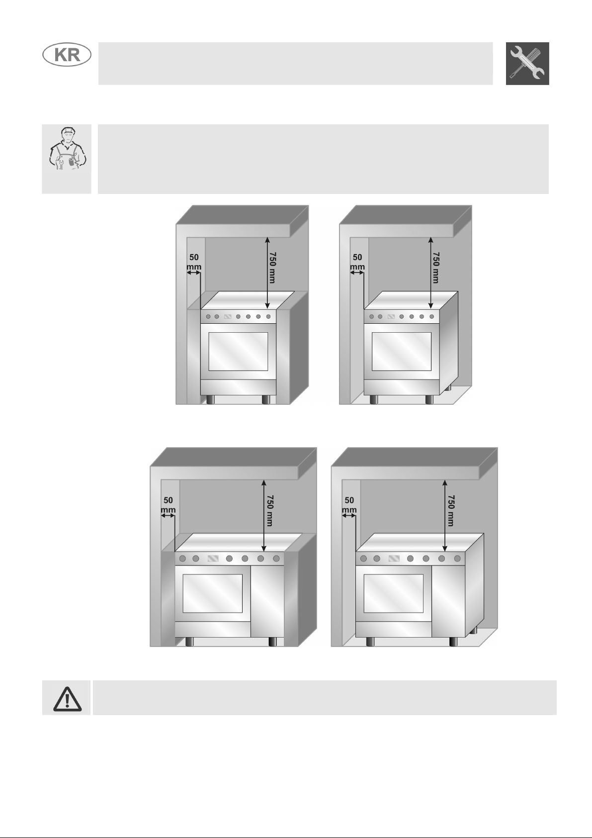
It can be placed against walls higher than the hob, at a distance of at least 50 mm from the side of th
appliance, as shown in the drawings A and B relating to the installation classes. Wall units o
extractor hoods located above the hob must be at least 750 mm away from it.
Instruction for the installer
A
B
Built-in appliance Free-standing installation
Built-in appliance Free-standing installation
A
B
The appliances with a gas bottle compartment and electric oven can only be installed as
class 1 (see fig. B).
6
Page 7
2.1 Electrical connection
Make sure that the power line voltage matches the specifications indicated on the rating plate located
inside the storage compartment.
This rating plate must never be removed.
If the appliance is hooked-up to the supply by means of a fixed connection, install a multipolar cut-out
device on the line, with contact opening distance equal to or greater than 3 mm, located near the
appliance and in an easily reachable position.
Hook-up to the supply may be fixed or with plug and socket. In the latter case the plug and socket
must be suitable for the cable employed and conform with the regulations in force. Regardless of the
type of connection, earthing of the appliance is absolutely obligatory. Before connection make sure
that the supply line is suitably earthed. Avoid the use of reducers, adapters or shunts.1
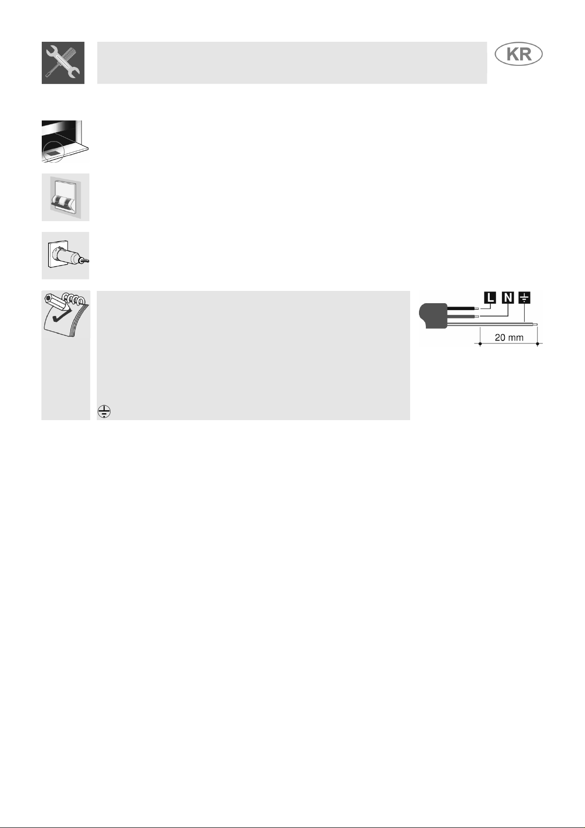
If the power cable is replaced, the wire section on the new cable must
not be less than 1.5 mm2 (3 x 1.5 cable), keeping in mind that the end to
be connected to the hob must have the ground wire (yellow-green)
longer by at least 20 mm. Use on l y H 0 5 V 2 V 2 - F c a b l e o r s im ilar w h i c h h a s
a maximum temperature of 90°C. This must be done by a specialised
technician, who must connect the cooker to the electricity supply
according to the diagram shown here.
L = brown
N = blue
= yellow-green.
Instruction for the installer
7
Page 8
Instruction for the installer
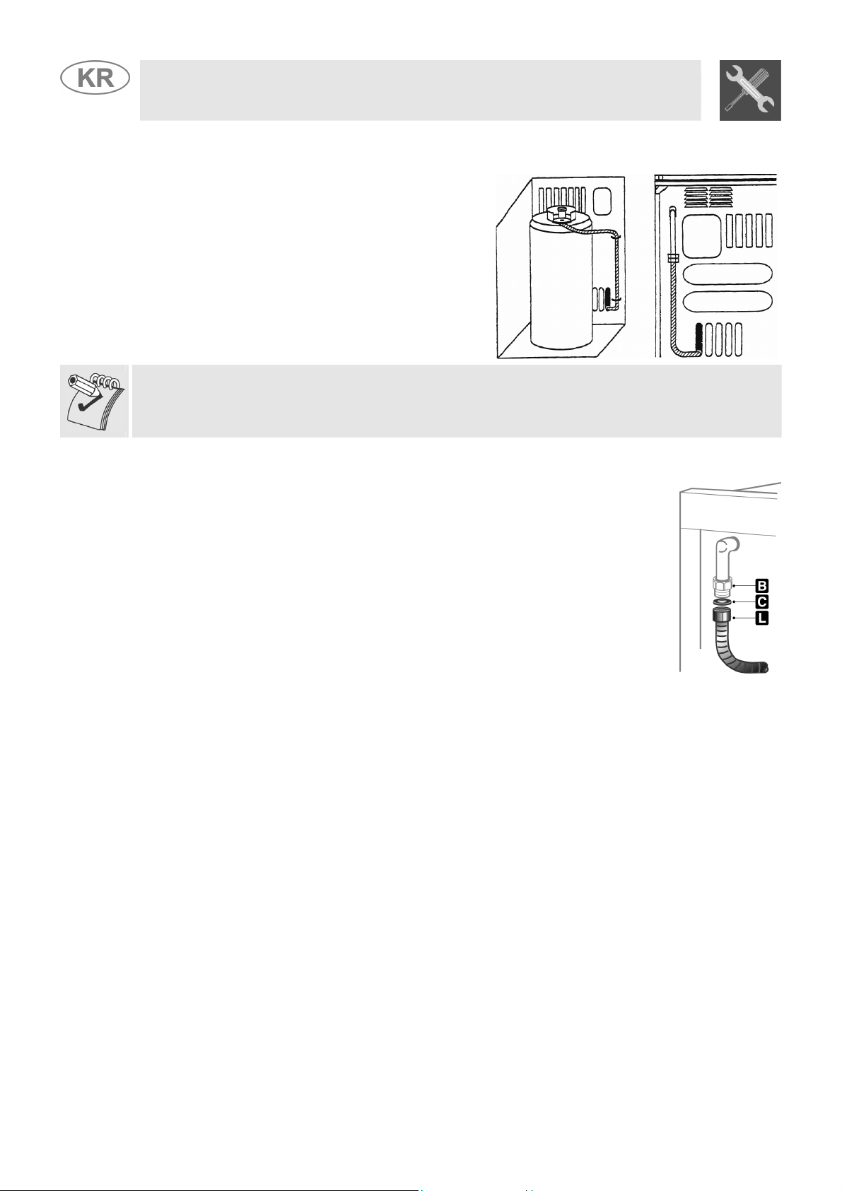
2.1.1 Connection to the gas bottle inside the compartment in the cooker (on some models
only)
Open the side door and put in a gas bottle (max. 15
kg). Fit one end of the pipe to the pipe holder and fix it
to one of the clamps supplied. Insert the pipe into the
bottle compartment through the hole in the back of the
cooker as shown in the diagram here. Fit the free end
of the pipe to the pressure regulator on the gas bottle:
fix it with the second clamp. Check for any leaks
using a soapy solution, never with a live flame.
To connect the cooker to a gas bottle, use a piece of regulation rubber pipe 1.4 m (± 0.05 m) long
2.2 Connecting to natural and LPG gas
(Please see connection diagram)
Make the connection to the appliance using flexible bayonet style hose in
accordance to B.S. 669. The hose connection at the rear of the appliance
has a ½” BSP internal thread. Please use seal C between the flexible
connection L and the appliance supply tube B. When making the
connection, make sure that no stress of any kind is applied to the cooker
and that the hose does not touch any sharp edges.
If connecting to LPG the bayonet hose must have red bands on it.
8
Page 9
/
3 ADAPTATION TO DIFFERENT TYPES OF GAS
Before performing any cleaning or maintenance work, detach the appliance from the electrical socket.
Instruction for the installer
This operation requires no primary air regulation.
The cooker hob is set for natural gas G20 (2H) at a pressure of 20 mbar for cookers with maxi oven,
and for LPG G30/G31 (3+) at a pressure of 28/37 mbar for cookers with gas-bottle compartments. In
the case of functioning with other types of gas the burner nozzles must be changed and the minimum
flame adjusted on the gas taps. To change the nozzles, proceed as described below.
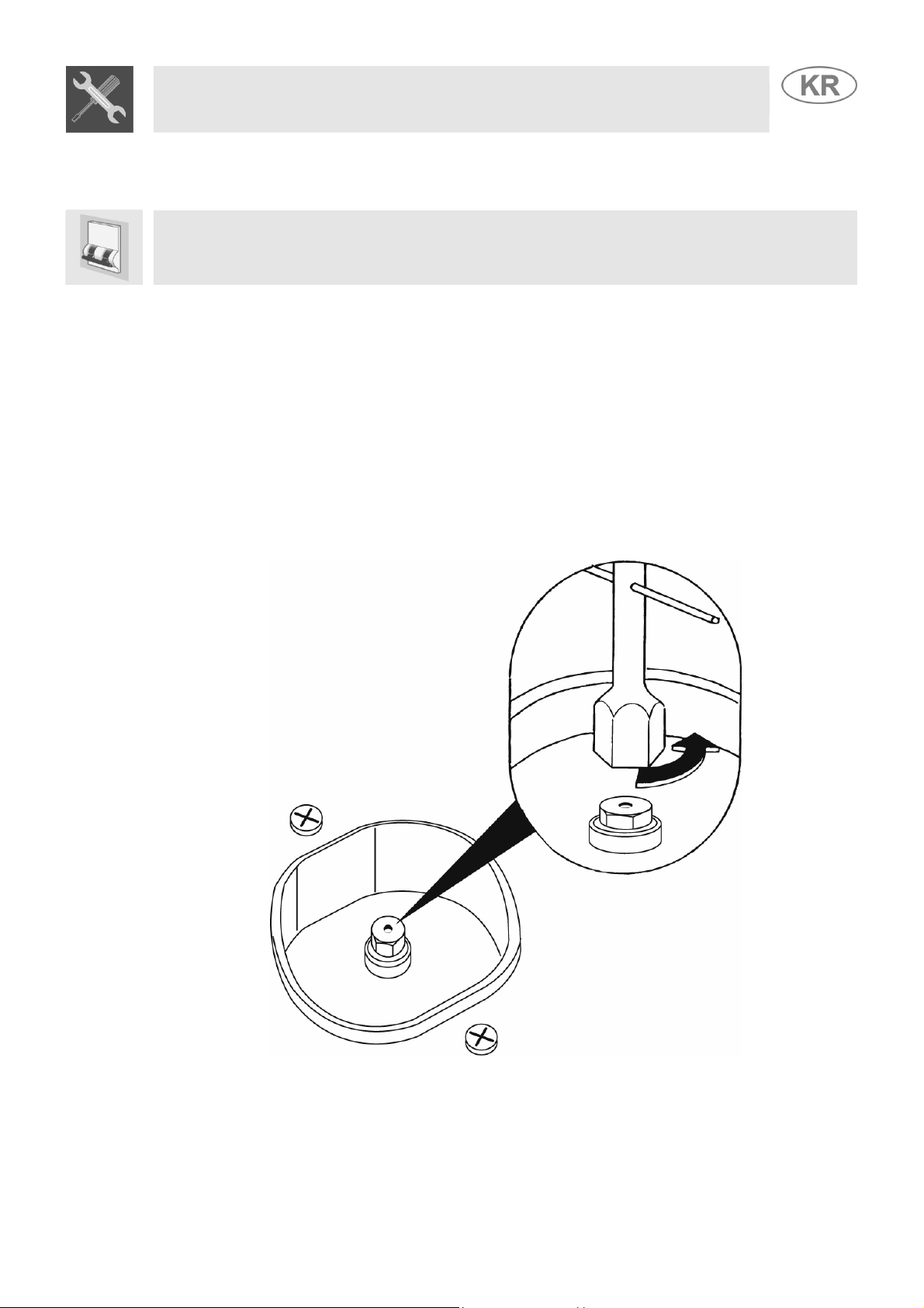
3.1 Replacement of nozzles on the hob
1. Extract the grids and remove all the caps and flame-spreader crowns;
2. unscrew the burner nozzles with a 7 mm socket wrench;
3. replace the nozzles according to the type of gas to be used and the description in paragraph “3.2
3.3 Burner and nozzle characteristics table”.
• Replace the burners in the correct position.
9
Page 10
Instruction for the installer
Burner
Auxiliary
Semi-rapid
Rapid (3)
Rapid (5)
Triple crown
Oven
Grill
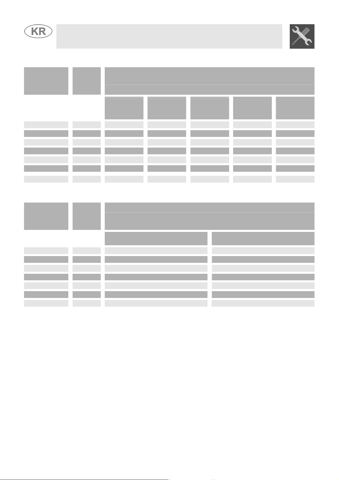
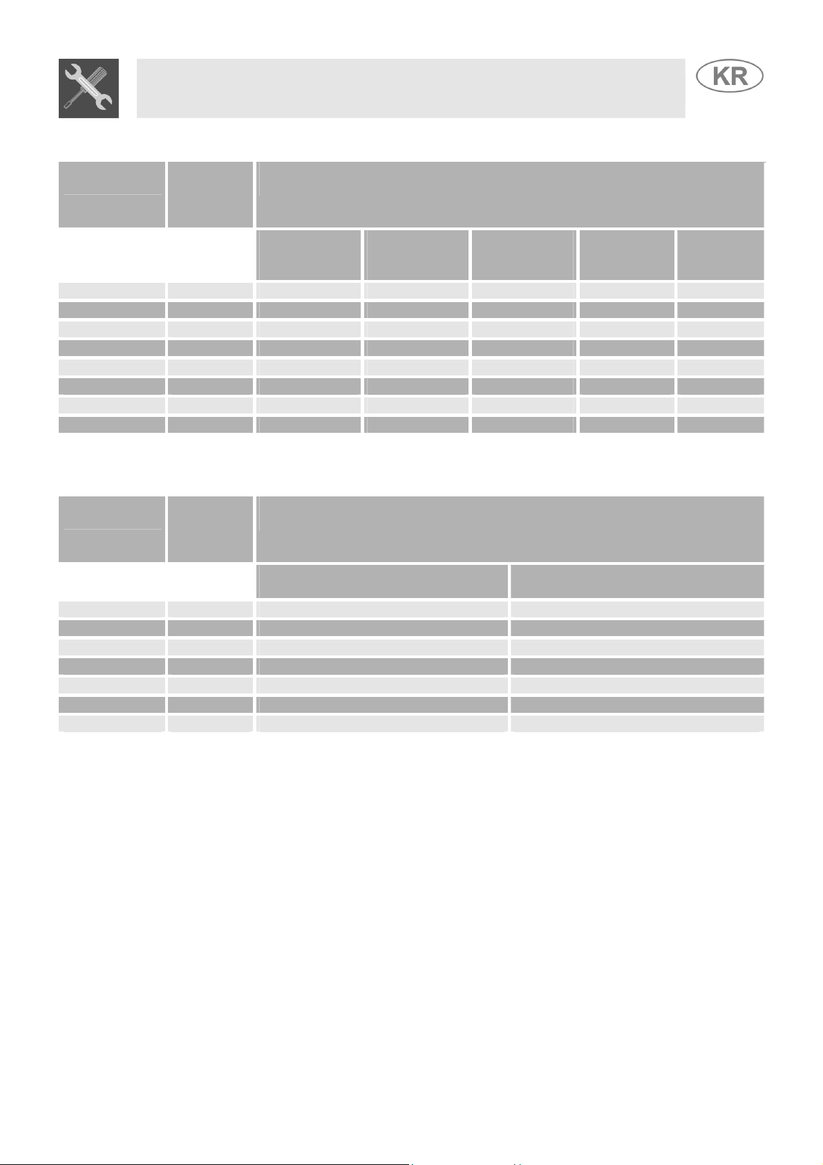
3.2 Burner and nozzle characteristics table (60 cm. models)
Rated
heating
capacity
(kW)
1.0 50 30 350 73 71
1.75 65 33 450 127 125
3.0 85 45 800 218 214
2.3 75 45 800 167 164
3.2 91 65 1500 233 229
3.2 87 48 850 233 229
3.0 87 // // 218 214
diameter
1/100 mm
Nozzle
LPG – G30/G31 28/37 mbar
By-pass
mm
1/100
Rated
Burner
heating
capacity
(kW)
Auxiliary
Semi-rapid
Rapid (3)
Rapid (5)
Triple crown
Oven
Grill
1.0 72 350
1.75 97 450
3.0 115 800
2.3 103 800
3.5 133 1500
3.2 130 850
3.0 130 //
NATURAL GAS – G20 20 mbar
Nozzle diameter
1/100 mm
Reduced
flowrate
(W)
Flowrate
g/h G30
Flowrate
Reduced Flowrate
(W)
g/h G31
10
Page 11
Instruction for the installer
Burner
Auxiliary 1 50 30 350 73 71
Semi-rapid 1.75 65 33 450 127 125
Rapid 3 85 45 800 218 214
Triple crown 3.2 91 65 1500 233 229
Fish pan 1.9 68 45 800 138 136
Oven 3.2 87 48 850 233 229
Maxi oven 5.2 110 59 1200 378 371
Grill 4.0 100 // // 291 286
Burner
Auxiliary 1 72 350
Semi-rapid 1.75 97 450
Rapid 3 115 800
Triple crown 3.5 133 1500
Fish pan 1.9 94 800
Oven 3.2 130 850
Maxi oven 5.2 164 1200
3.3 Burner and nozzle characteristics table (90 cm. models)
Rated
heating
capacity
(kW)
Rated
heating
capacity
(kW)
Nozzle
diameter
1/100 mm
Nozzle diameter
LPG – G30/G31 28/37 mbar
By-pass
mm
1/100
NATURAL GAS – G20 20 mbar
1/100 mm
Reduced
flowrate
(W)
Flowrate
g/h G30
Reduced Flowrate
Flowrate
g/h G31
(W)
11
Page 12

3.4 Arrangement of burners on cooking hob
Instruction for the installer
BURNERS
1. Auxiliary
2. Semi-rapid
3. Rapid (60 X 60)
4. Triple crown
5. Rapid (60 X 50)
3.5 Arrangement of burners on cooking hob
BURNERS
1. Auxiliary
2. Semi-rapid
3. Rapid
4. Triple crown
5. Large electric hob (1500W)
6. Small electric hob (1000W)
7. Fish pan
12
Page 13

Instruction for the installer
To adjust the oven burners follow the procedure described below from
3.6 Adjustment of the oven burner (only for gas oven models)
inside the oven:
• Open the oven door;
• Remove the oven dish and shelf.
• Lift up the oven floor and remove.
3.6.1 Replacement of the oven/grill burner nozzle
• Loosen the fixing screws A on the oven burner.
• Push the burner B towards the right to get to the
nozzle.
• Use a 13 socket wrench to change the nozzle, fitting
the one for the type of gas to be used (see point
“3.2/3.3 Table of burner and nozzle characteristics”).
3.6.2 Regulation of the primary air on the oven/grill burner
• Loosen the register screws “A” on the air regulation coupling.
• Turn the register coupling “B” to the position corresponding to the type of gas
to be used according to the table below.
• Tighten the register screws and mount the seals.
• Once the operation is completed reassemble the burner correctly.
X =
NATURAL (N)
G30/G31 (LPG)
5 mm 15 mm
13
Page 14

e
e
o
After replacing the nozzles, reposition the flame-spreader crowns, the burner caps and the grids.
Light the burner and turn it to the minimum position
4 FINAL OPERATIONS
Following adjustment to a gas other than the preset one, replace the gas adjustment label fixed to th
appliance with the one corresponding to the new gas. This label is in the packet together with th
nozzles.
4.1 Regulation of the hob burner minimum level for natural gas
knob and turn the adjustment screw at the side of the tap rod until the
correct minimum flame is achieved.
Replace the knob and check burner flame stability: (rapidly turning the
knob from maximum to minimum position, the flame should not go out).
Repeat the operation on all the gas taps.
For models with valves, keep the knob at minimum level for about 1 minute to keep the flame lit and t
activate the safety device.
Instruction for the installer
. Extract the gas tap
For regulating the minimum with LPG, the screw at the side of the tap rod must be turned clockwise all
The oven thermostat is equipped with a by-pass to regulate the minimum level, which is visible
4.2 Regulation of the hob burner minimum level for LPG
the way.
The bypass diameters for each individual burner are shown in paragraph “3.2 / 3.3 Burner and nozzle
characteristics table”. Once the regulation has been completed, replace the seal on the by-passes
using paint or similar materials.
4.3 Regulation of the oven burner minimum level
underneath the thermostat knob.
When the gas type is changed, the by-pass should be regulated as follows:
1. Turn on the oven burner to maximum for 10/15 minutes with the door closed and without the floor.
Turn the knob to the minimum temperature, remove the knob and regulate using a flat
screwdriver.
2. For LPG turn the by-pass screw clockwise as far as it will go. The by-pass diameter is shown in
the paragraph “3.2 / 3.3 Burner and nozzle characteristics table”.
3. For natural gas, regulate the by-pass so that turning the thermostat knob from minimum to
maximum the flame remains stable and constant. Once the regulation has been completed,
replace the seal on the by-pass using paint or similar materials. Close the oven door and make
sure that the burner stays on minimum.
14
Page 15

4.4 Mounting the rear top skirtboard (where applicable)
• Loosen screws A located beneath the skirt.
• Loosen nuts B.
• Position the skirt above the top, taking care to
align pins C with holes D.
• Secure the skirt to the top by tightening screws
E.
4.5 Wall fixing (where applicable)
• Stretch out the chain attached to the cooker
horizontally so that the other end touches the
wall.
• Mark the wall in the position where the hole is
to be drilled.
• Drill the hole, insert the finned dowels and
attach the chain.
• Move the cooker up against the wall.
Instruction for the installer
4.6 Positioning and levelling of the appliance
Having carried out the electricity and gas hook-up, level the appliance using the four adjustable legs.
For best cooking the appliance must be perfectly level.
15
Page 16

e
All the oven controls are grouped together on the front panel. The table below provides a description
5 DESCRIPTION OF CONTROL PANEL
of the symbols used.
FRONT RIGHT BURNER
Instruction for the user
CENTRAL BURNER
BACK CENTRAL BURNER
FRONT CENTRAL BURNER
If the cooker is equipped with an electronic programmer, before using the oven make sure that th
BACK RIGHT BURNER
BACK LEFT BURNER
FRONT LEFT BURNER
symbol ; appears on the display. See paragraph “8.1 Clock adjustment”.
The flame is lit by pressing the knob and turning it anticlockwise to minimum
flame
. To adjust the flame turn the knob between maximum ( ) and minimum
GAS OVEN THERMOSTAT KNOB
OVEN LIGHT / ROTISSERIE / GRILL
SWITCH
ELECTRIC OVEN FUNCTION KNOB
OVEN FUNCTION
COOKING HOB BURNER COMMAND KNOB
). The burner goes out when the knob is returned to the position .
(
GAS OVEN THERMOSTAT KNOB
(CERTAIN MODELS ONLY)
This knob is used to ignite the gas burner inside the oven. The cooking
temperature is selected by turning the knob anticlockwise to the desired setting,
between Min. and 275°C.
For information on how to ignite the gas oven, see point “ 7.3 Use of the gas oven ”.
Fo r i n f or m a t i o n o n ho w t o i g n i te t h e g r i l l b ur n e r , s e e p oi n t “7.5 Use of the gas grill ”
OVEN LIGHT / ROTISSERIE / GRILL SELECTOR KNOB
(CERTAIN MODELS ONLY)
This knob allows the user to activate the Grill / Rotisserie function or to switch on
the light inside the oven to check the point reached in cooking the food.
CAUTION: IT IS NOT POSSIBLE TO OPERATE THE GAS OVEN AND THE
GRILL / ROTISSERIE SIMULTANEOUSLY.
16
Page 17

Instruction for the user
Selection of cooking temperature is carried out by turning the knob clockwise to
the required temperature, between 50° and 260°C.
The tell-tale light comes on to indicate that the oven is warming up. When it goes
out it means that the required temperature has been reached. Regular flashing
means that oven temperature is being constantly maintained at the programmed
level.
The various electric oven functions are suitable for different cooking modes.
After selecting the function required, set the cooking temperature using the
thermostat knob.
OVEN LIGHT
ELECTRIC OVEN THERMOSTAT KNOB
(CERTAIN MODELS ONLY)
STATIC ELECTRIC OVEN CONTROL KNOB
(CERTAIN MODELS ONLY)
LARGE GRILL FUNCTION
STATIC OVEN FUNCTION
LOWER RESISTANCE FUNCTION
VENTILATED ELECTRIC OVEN FUNCTION KNOB
SMALL GRILL FUNCTION
SMALL GRILL FUNCTION +
ROTISSERIE (IN THOSE MODELS WITH
ROTISSERIE)
(CERTAIN MODELS ONLY)
The various electric oven functions are suitable for different cooking modes.
After selecting the function required, set the cooking temperature using the
thermostat knob.
OVEN LIGHT
STATIC OVEN FUNCTION
GRILL FUNCTION
GRILL AND VENTILATOR FUNCTION
LOWER RESISTANCE AND
VENTILATOR FUNCTION
VENTILATED OVEN FUNCTION
17
Page 18

r
e
6 USE OF THE COOKING HOB
6.1 Lighting of the cooking hob burners
Before lighting the hob burners check that the flame caps are in the correct position and that thei
burner caps are in place, making sure that the holes A in the flame caps correspond to the spark
plugs and thermocouples.
Before lighting the burners lift the glass cover; before lowering the cover, turn off all the burners and
wait for them to cool down.
The optional grid B is for use with “woks” (Chinese pans).
The supplied reduction rest C is used for small pans.
Instruction for the user
The drawing next to each knob shows the corresponding burner. The appliance
has an electronic lighting device. Simply press and turn the knob anticlockwise to
the minimum flame symbol
, until the ring is lit. Hold the knob down for a few
seconds to allow the thermocouples to heat up. The burner may go out when the
knob is released: this is because the thermocouple has not been sufficiently
heated. Repeat the operation holding down the knob for a little longer. This
operation is not necessary for burners without thermocouples.
For models with thermocouples, if the burner should accidentally go out, a safety device will b
activated which stops the gas flow even if the tap is open.
6.2 Practical advice for using the cooking hob burners
For better use of the burners and lower gas consumption, use covered containers that are proportional
in size to the burner to prevent the flame from licking the sides (see paragraph “6.3/6.4 Diameter of
containers”). When water reaches the boiling point, lower the flame so that it doesn’t overflow. To
avoid burns or damage to the hob, all recipients or griddle plates must be placed within the perimeter
of the cooking hob. All containers have to have a flat and smooth bottom. When using fats or oils, be
extremely careful that they don’t overheat and catch fire.
If the flame accidentally goes out, turn off the control knob and wait at least 1 minute before trying to
re-light the burner.
18
Page 19

6.3 Diameter of containers (60 cm. models)
Instruction for the user
6.4 Diameter of containers (90 cm. models)
BURNERS
(60 X 50)
1. Auxiliary
2. Semi-rapid
5. Rapid
Ø min. and
max. (in cm.)
12 – 14
16 – 22
18 – 24
BURNERS
(60 X 60)
1. Auxiliary
2. Semi-rapid
3. Rapid
4. Triple crown
Ø min. and
max. (in cm.)
12 – 14
16 – 24
18 – 26
18 – 26
BURNERS
1. Auxiliary
2. Semi-rapid
3. Rapid
4. Triple crown
7. Fish burner
Ø min. e max.
(in cm.)
12 – 14
16 – 22
18 – 26
18 – 26
use special
oval-shaped
pan
19
Page 20

6.5 Switching on the electric hob
6.5.1 Switching on the electric hobs
Instruction for the user
The cookers are equipped with hobs of different diameters. These are controlled by a switch and are
turned on by turning the knob to the desired position. On the front panel above each knob a small
drawing shows which hob corresponds to each knob. A yellow warning light lights up when the hob is
switched on.
6.5.2 How to use the electric hobs
The rapid hobs offer the advantage of ultra-rapid cooking. Purely as an example the regulation table
for the hobs is shown below.
RAPID HOBS
0
1
2
3
4
5
6
HEAT INTENSITY
Off
Weak
Soft
Slow
Medium
Strong
Very strong
POSSIBLE COOKING
-
To melt butter, chocolate, etc.
To heat small amounts of liquid.
To heat larger amounts of liquid.
To defrost frozen food and prepare stews, cooking at
or just below boiling point.
To cook food which has to reach boiling point, to roast
delicate meat or fish.
For roasts, steaks and large boiled joints.
To boil large amounts of water, to fry.
WARNING
When switching on the hob for the first time, or if the hob has not been used for a
long time, to remove any humidity from the insulating material it should be dried
out by placing the hob on position 1 for 30 minutes.
To use correctly remember to:
• Switch the hob only after having placed the pan on it.
• Use flat and thick bottomed pans.
• Never use pans which are smaller than the hob.
• Dry the bottom of the pan before placing it on the hob.
• After use, to make sure that the surfaces are clean and long lasting, the
electric hob must be treated with specific cleaning products which are
available on the market. This necessary operation prevents oxidisation (rust
formation).
• When cooking with flammable oils and fats, never leave the appliance.
• The hobs will stay hot for a long time after use: do not touch them or place
any objects on them.
• Before switching on the electric hobs, lift up the glass cover on the cooker;
before closing it, switch off the hobs and wait for them to cool down.
• If any dents appear in the hob surface, switch it off immediately and contact
the nearest authorised servicing centre.
20
Page 21

y
d
s
s
o
e
Instruction for the user
7.2 Cooling system
Open the oven door completely, press the thermostat knob and turn it clockwise
7 USE OF THE OVEN
For those models with electronic programmer, before using the oven make sure that the displa
shows the symbol .
For those models with analogue clock and timer, place on the symbol .
7.1 Warnings and general advice
Using the oven and the grill for the first time, heat them to the maximum temperature (260°C for
electric oven and 275°C for gas oven) for as long as it takes to burn off any production oil residues
which could give a nasty flavour to the food. After a power cut, the oven display will flash intermittently
and show
EQUIPPED MODELS)”.
The oven accessories which may come into contact with food are made from materials which
conform to the standing directives.
WARNING: the gas oven is lit with the door open. The oven is equippe
with a safety system which stops the burners being lit when the door i
closed. If this is done wrongly, open the door and wait for a few moment
before lighting once more.
To prevent any steam in the oven creating problems, open the door in tw
stages: half open (5 cm approx.) for 4-5 seconds and then fully open. To access
food, always leave the door open as short a time as possible to prevent th
temperature in the oven from falling and ruining the food.
The oven is equipped with a cooling system which automatically comes on upon a few minutes after
the oven has been turned on.
Fans cause a steady outflow of air from above the door which may continue for a brief period of time
even after the oven has been turned off.
7.3 Use of the gas oven
7.3.1 Electronic spark lighting
to max. temperature. The electronic spark lighting device will be enabled
automatically. Once the oven is lit, hold the knob down for a few seconds to allow
the thermocouple to heat up.
This device should not be enabled for more than 15 seconds; if after this time the
burner has not come on, stop, fully open the oven door and try again after one
minute.
7.3.2 Manual lighting
Open the oven door completely and turn the thermostat knob. Place a lit
match to the mouth of the flame pipe A in the centre of the oven floor
and press the thermostat knob. Once the oven is lit, hold the knob down
for a few seconds to allow the thermocouple to heat up and check that
the oven is lit through the inspection hole B. Choose the cooking
temperature by turning the knob clockwise to the desired temperature,
between 50° and 275°C.
. To adjust refer to paragraph "8 ELECTRONIC PROGRAMMER (ONLY ON
If the burner is accidentally switched off, turn the knob to the off position ( ) and wait for one minute
before lighting again.
21
Page 22

Instruction for the user
7.4 Use of the electric grill
7.4.1 Using the grill in cookers with electric oven
For short cooking proced ures, such as the final crisping o f meat which is already cooked, s elect the
static grill function
and turn the thermostat knob to the maximum temperature. The fan grill function
(certain models only) allows actual cooking procedures to be carried out, thanks to the fan function
which ensures that the heat penetrates into the food. For this cooking mode, select the fan grill
function
200° C).
7.4.2 Using the grill in gas cookers
To activate this function, the oven burner must first be switched off by turning the
relative knob back to the position
and turn the thermostat knob to the ideal cooking temperature (never set at more than
; the switch must then be turned to .
CAUTION: IT IS NOT POSSIBLE TO OPERATE THE GAS OVEN AND THE
GRILL / ROTISSERIE SIMULTANEOUSLY.
Fit the supporting frame onto the second runner
7.4.3 Operation of the grill + rotisserie
Both the static and the fan grill functions can be used for cooking in combination with the rotisserie. Fit
the spit rod into the rotisserie bushing, select the
or or fan grill function and turn the
thermostat knob to the temperature of choice (never set at more than 200° C).
7.4.4 Using the rotisserie in cookers with maxi oven
up from the bottom so that the seat to take the
rod projects outside the oven. Place the rod as
shown in the diagram (1) and push the frame
into the oven until the end of the rod reaches
the hole in the rotisserie motor. Now push the
rotisserie rod to the left until it reaches the
position shown in the diagram (2). To activate
this function, turn the switch to (
).
These operations must be carried out with
the oven switched off and cold.
When cooking is over, use the to ol provided to
extract the rod from the hole (3) and remove
the frame (4) to bring the rotisserie rod out of
1
2
the oven cavity.
7.4.5 Using the rotisserie in cookers with standard ovens
Place the rotisserie frame “B” on the second
runners up from the bottom and insert the rod
“A” in the hole in the back of the oven.
22
3
4
Page 23

t
t
d
r
Instruction for the user
If your cooker is equipped with knob guard, when
How to use the grill
Once the grill is lit, the red warning light will come on. Leave the oven to heat up for five minutes
before placing the food inside.
Food should be flavoured and basted with oil or melted butter before cooking. An oven dish should be
used to contain the sauces.
The food should be placed on the oven shelf which is positioned on one of the guides supplied with
the different ovens, following the instructions below:
FOOD GRILLE ON THE SHELF
Flat or thin meat
Rolled roast joints
Poultry
WARNINGS
• Cooking procedures in this mode must never last more than 60 minutes.
• In models with gas oven, the door must be half-open on the first catch during grilling and
grill-rotisserie cooking.
• In models with electric oven, the door must be close during grilling and grill-rotisserie
cooking.
• To avoid dangerous overheating when the oven or the grill is used, the glass cover mus
always be up. The electric grill and the gas oven cannot be used at the same time.
• During and after use the accessible parts of the oven may be very hot, and children mus
always be kept at a distance.
• During cooking with the rotisserie, one of the oven trays provided with the cooker shoul
be placed in the bottom of the oven, inserting it on the bottom runners, in order to collect
the grease and fats which may be formed.
cooking using the grill or grill + rotisserie it must be
fitted as shown here, fitting the slots "A" onto the pins
"B" in the top of the oven.
1
2 – 3
2 – 3
7.5 Use of the gas grill
7.5.1 Manual lighting of the gas grill burner
Having opened the oven door, press the knob and turn it clockwise to the grill
match to the burner on the roof of the oven.
Once the burner is lit, hold the knob down for about 10 seconds. If the burner does not stay lit after
this time, release the knob and wait for at least one minute before trying again. If the burne
accidentally goes out, turn the knob to the off position ( ) and wait at least one minute before lighting
again.
position, placing a lit
23
Page 24

y
7.5.2 Electric lighting of the gas grill burner
Having opened the oven door, press the knob and turn it clockwise to the grill
Once the burner is lit, hold the knob down for about 10 seconds. If the burner has not come on by this
time, release the knob and wait for at least one minute before trying again. If the burner accidentally
goes out, turn the knob to the off position (
During a power cut the burner can always be lit with a match.
Instruction for the user
position.
) and wait at least one minute before lighting again.
A storage compartment, accessible by pulling on the top edge
The gas bottle compartment can be reached through the side
7.6 Storage compartment
of the door, is located beneath the oven.
Never store flammable materials such as rags, paper or the
like. The compartment is intended only for holding the metal
accessories of the range.
Never open the storage compartment when the oven is on and still hot. The temperature inside ma
be very high.
7.7 Gas bottle compartment (certain models only)
door and can also be used as an ordinary cupboard.
The 3 grilles shown in the diagram are not supplied with the
appliance but can be purchased separately in any of the
Authorised Servicing Centres.
24
Page 25

g
Instruction for the user
8 ELECTRONIC PROGRAMMER (ONLY ON EQUIPPED MODELS)
8.1 Clock adjustment
When using the oven for the first time, or after a power failure, the display flashes regularly and
indicates
LIST OF FUNCTIONS
MINUTE-COUNTER KEY
COOKING TIME KEY
END-OF-COOKING KEY
DECREASE TIME KEY
INCREASE TIME KEY
. Press the keys and at the same time the keys or : each single press
changes the time by 1 minute either up or down.
Before setting the programmer activate the desired function and temperature.
8.2 Semiautomatic cooking
Use this setting for automatic oven switch-off at the end of cooking time.
By pressing key
press keys
Release key
together with symbols A and
or to set the cooking time.
to start the programmed cooking time count. The display will now show the right time
, the display lights up, showing ; keep the key pressed and at the same time,
.
8.3 Automatic cooking
Use this setting to automatically start and stop the oven.
By pressing key
press keys
By pressing key
the same time, press keys
programmed count and the display will show the right time together with symbols A and
After set-up, to see the cooking time remaining, press the key ; to see the end of cooking time press
the key . Set-up with incoherent values is logically prevented (e.g. the contrast between a cookin
time and a longer period will not be accepted by the programmer).
, the display lights up showing ; keep the key pressed and at the same time,
or to set the cooking time.
the sum of the right time + cooking time will appear; keep the key pressed and at
or to regulate the end of cooking time. Release key to start the
.
25
Page 26

8.4 End of cooking
When cooking is over, the oven will automatically switch off and, at the same time, an intermittent
alarm will sound. After switching off the alarm, the display will once again show the right time together
with the symbol
Instruction for the user
, indicating that the oven has returned to manual operation mode.
8.5 Adjusting alarm volume
The acoustic alarm has three different settings. These can be operated, while the alarm is sounding,
by pressing key
8.6 Switching off the alarm
The alarm switches off automatically after seven minutes. They can be manually de-activated by
pressing the keys
8.7 Minute Counter
The programmer can also be used as a simple minute counter. By pressing key , the display shows
.
and together.
; keep the key pressed and at the same time press keys or . On releasing the key ,
programmed counting will begin and the display will show the current time and the symbol
After set-up, to see the remaining time, press the key .
.
Use as a minute counter does not interrupt functioning of the oven at the end of the programmed time.
8.8 Cancellation of set data
Once the programme has been set, keep the key of the function to be cancelled pressed, while at the
same time
is reached by means of variation keys or . Time cancellation will be considered
as end-of-cooking time by the programmer.
8.9 Changing the set data
The cooking data entered can be changed at any time by keeping the function key pressed and at the
same time adjusting the keys
or .
26
Page 27

Instruction for the user
This component allows an on-off beeper to be set to indicate the end of the cooking time. It is
9 DIGITAL TIMER (CERTAIN MODELS ONLY)
therefore just a timer, with no programming functions.
LIST OF FUNCTIONS
TIME-SETTING BUTTON
VALUE DECREASE BUTTON
VALUE INCREASE BUTTON
9.1.1 Setting the time
When the oven is used for the first time, or after a power blackout, the display flashes on and off at
regular intervals showing
. Press the key and use the or keys to set the current time.
9.1.2 Setting the timer
To set the timer, press the
When the
key is released, after 5 seconds the countdown will start; once this finishes, an acoustic
key and keep it pressed until the required number of minutes is shown.
device will sound.
During the countdown the display will show the
symbol; pressing the key displays the current
time for 5 seconds.
9.1.3 Deactivating the acoustic device
The acoustic device stops sounding automatically after seven minutes. It can be deactivated in
manual mode by pressing the
key.
9.1.4 Adjusting the volume of the acoustic device
The volume can be adjusted (3 settings) while it is in operation by pressing the key.
9.1.5 Modifying the data set
The timer data set can be modified at any moment by pressing the
or keys.
10 ANALOGUE CLOCK (ONLY ON EQUIPPED MODELS)
The mechanical timer is set by turning the knob clockwise.
The timer can be set from 0 to 55 minutes. At the end of the cooking time, an
alarm signal will be heard: to stop the alarm turn the external part of the knob to
position
.
The clock is set by pulling the knob and turning it clockwise.
27
Page 28

s
Instruction for the user
11 CLEANING AND MAINTENANCE
11.1 Cleaning stainless steel and enamelled versions
To maintain stainless steel in good condition it must be cleaned regularly after each use, once it ha
cooled down.
11.1.1 Ordinary Daily Cleaning
To clean and preserve the stainless steel surfaces, always use only specific products that do not
contain abrasives or chlorine-based acids.
How to use: pour the product on a damp cloth and wipe the surface, rinse thoroughly and dry with a
soft cloth or deerskin.
11.1.2 Food stains or residues
Do not use metallic sponges or sharp scrapers: they will damage the surface.
Use normal non-abrasive products for steel, and a wooden or plastic tool if neces sary.
Rinse thoroughly and dry with a soft cloth or deerskin.
Do not allow residues of sugary foods (such as jam) to set inside the oven. If left to set
for too long, they might damage the enamel lining of the oven.
11.2 Cleaning of cooking hob components
11.2.1 The glass cover
The cover can be removed from the hinges by lifting it upwards when it is open.
This makes cleaning easier.
If liquids are spilt on the closed lid, remove them thoroughly with a rag before
opening it.
11.2.2 Grids
Remove the grids and clean them in warm water with a non-abrasive detergent, taking care to remove
any incrustations. Replace them on the cooking hob.
Continuous contact of the grids with the flame can cause the paint near the hot areas to be altered.
This is completely natural and does not compromise the functionality of the com ponent.
11.2.3 Burner caps and flame cap crowns
The caps and flame-spreader crowns are extractable to facilitate cleaning.
Wash them in hot water with non-abrasive detergent, taking care to
remove any incrustations, and wait until they are perfectly dry.
CAUTION: do not wash these components in a dishwasher.
The burners can be left to soak in hot water and detergent.
Replace the flame-spreader crowns, checking that they are positioned in
their housing with their respective caps, taking care that flame-spreader
holes A correspond to the spark plugs and the thermocouples.
28
Page 29

Instruction for the user
To function properly the spark plugs and thermocouples must always be clean (on
11.2.4 The spark plugs and thermocouples
the models which are equipped with them). Check them regularly and clean with a
damp cloth if necessary. Any dry residues can be removed with a toothpick or a
needle.
11.3 Cleaning of oven
For best oven upkeep clean regularly after having allowed to cool. Take out all removable parts.
The door glass should always be kept clean. Use absorbent kitchen paper to clean. In case of tough
• Clean the oven grill with hot water and non-abrasive detergent. Rinse and d ry.
• Clean the internal walls of the oven with a soft ammoniac-soaked cloth. Rinse and dry. If there are
11.4 Door glass
spots, clean with a damp sponge using regular detergent.
still stains or drops, place a damp ammoniac-soaked cloth on the bottom of the oven, close the
door and after a few hours wash the oven with hot water and liquid detergent. Rinse and d ry.
29
Page 30

12 EXTRAORDINARY MAINTENANCE
The oven may require extraordinary maintenance or replacement of parts subject to wear such as
seals, bulbs, and so on. The following instructions describe how to carry out these minor maintenance
operations.
Before any intervention, disconnect the power supply of the device.
12.1 Lubrication of the taps and gas oven thermostat
In time the taps and gas oven thermostat may be difficult to turn or may be blocked. Clean them inside
and replace the lubrication grease. This operation should be carried out by a specialised
technician.
12.2 Replacement of light bulb
Remove cover A by twisting anticlockwise , replace bulb B with another similar bulb (25 W). Refit the
cover A.
Instruction for the user
Only use oven bulbs (T 300°C).
12.3 Removing the door
Raise levers B and hold the door on both sides with both
hands near hinges A and. Lift up the door forming an
angle of about 45° and remove. To refit, slide the hinges
A in the grooves, drop the door and release levers B.
12.4 Oven door seal
To permit thorough cleaning of the oven, the seal may be removed. Before
removing the seal, take off the door as described above. Once the door has
been taken off, lift the tabs at the corners as shown in the figure.
30
Page 31

Page 32

914771991/ C
 Loading...