

Page 1

INSTRUCTION MANUAL
FS61XNG8
FREE STANDING COOKER
Page 2

ENGLISH
Thank you for choosing our product.
We advise you to read this manual carefully. It contains all necessary instructions for maintaining
unaltered the appearance and functional qualities of the appliance.
3 - 34
Page 3

Contents
@
1. INSTRUCTIONS FOR USE ..................................................................................................... 4
2. SAFETY PRECAUTIONS ........................................................................................................ 6
3. ENVIRONMENTAL CARE ....................................................................................................... 8
3.1 Our environmental care .................................................................................................................................. 8
3.2 Your environmental care ................................................................................................................................. 8
4. GET TO KNOW YOUR APPLIANCE ....................................................................................... 9
4.1 Description of the controls on the front panel ................................................................................................. 9
5. AVAILABLE ACCESSORIES ................................................................................................. 10
5.1 Using the rack or tray .................................................................................................................................... 10
5.2 Using the support rack .................................................................................................................................. 11
5.3 Using the reduction pan stands .................................................................................................................... 11
5.4 Using the rotisserie rod (on some models only) ............................................................................................ 11
6. USING THE COOKING HOB ................................................................................................. 12
6.1 General warnings and advice ....................................................................................................................... 12
6.2 Lighting the hob burners ............................................................................................................................... 12
6.3 Practical hints for using the hob burners ....................................................................................................... 12
6.4 Pan diameters ............................................................................................................................................... 13
6.5 Glass lid (on some models only) ................................................................................................................... 13
7. USING THE OVEN ................................................................................................................ 14
7.1 Before using the appliance ........................................................................................................................... 14
7.2 Oven runners ................................................................................................................................................ 14
7.3 Storage compartment (on some models only) .............................................................................................. 14
7.4 Cooling fan system (on some models only) .................................................................................................. 14
7.5 Internal light .................................................................................................................................................. 14
7.6 General warnings and advice for use ........................................................................................................... 15
7.7 Electronic programmer .................................................................................................................................. 16
8. COOKING WITH THE OVEN ................................................................................................18
8.1 Cooking advice and instructions ................................................................................................................... 19
8.2 Cooking process information table ................................................................................................................ 20
9. CLEANING AND MAINTENANCE ......................................................................................... 21
9.1 Cleaning stainless steel ................................................................................................................................ 21
9.2 Ordinary daily cleaning ................................................................................................................................. 21
9.3 Food stains or residues ................................................................................................................................. 21
9.4 Cleaning the cooking hob parts .................................................................................................................... 21
9.5 Cleaning the oven ......................................................................................................................................... 23
9.6 VAPOR CLEAN: assisted oven cleaning (on some models only) ................................................................. 24
10. EXTRAORDINARY MAINTENANCE .................................................................................. 26
10.1 Replacing the light bulb ............................................................................................................................... 26
10.2 Removing the door ...................................................................................................................................... 26
10.3 Removing the door seal (not on pyrolitic models) ....................................................................................... 27
10.4 Removing the internal glass panels ............................................................................................................ 27
11. INSTALLATION ................................................................................................................... 28
11.1 Clearances above and around domestic appliances .................................................................................. 28
11.2 Combustion gas discharge ......................................................................................................................... 28
11.3 Gas connection ........................................................................................................................................... 29
11.4 Room ventilation ......................................................................................................................................... 29
11.5 Extraction of the combustion products ........................................................................................................ 29
11.6 Electrical connection ................................................................................................................................... 30
11.7 Positioning the skirt (on some models only) ................................................................................................ 31
11.8 Positioning and levelling the appliance ....................................................................................................... 31
11.9 Wall mounting brackets (where present) ..................................................................................................... 31
11.10 Wall fixing .................................................................................................................................................. 32
12. ADAPTATION TO DIFFERENT TYPES OF GAS .............................................................. 33
12.1 Replacement of nozzles on the hob ............................................................................................................ 33
12.2 Arrangement of burners .............................................................................................................................. 33
12.3 Burner and nozzle characteristics table ...................................................................................................... 34
12.4 Final operations .......................................................................................................................................... 34
IINSTRUCTIONS FOR THE USER: these instructions contain user recommendations, a
description of the controls and the correct procedures for cleaning and maintenance of the
appliance.
INSTRUCTIONS FOR THE INSTALLER: these are intended for the authorised person who must
install the appliance, set it functioning and carry out an inspection test.
Further information about the products can be found at www.smeg.com
3
Page 4
General instructions
1. INSTRUCTIONS FOR USE
This manual is an integral part of the appliance. It must be kept in its entirety and in an accessible place
for the whole working life of the appliance. We urge you to read this manual and all the information it
contains carefully before using the appliance. Installation must be carried out by qualified personnel in
accordance with the regulations in force. This appliance is intended for domestic use and conforms to
the EC directives currently in force. The appliance has been built to carry out the following functions:
cooking and heating up food; all other uses are considered unsuitable.
These instructions are valid only for the destination countries whose identifying symbols are included on
the cover of this manual.
Never obstruct the openings and slits provided for ventilation and heat dispersal; this may cause
malfunctions.
Do not use this appliance for heating rooms.
The identification plate with technical data, serial number and brand name is located in an exposed
position either in the drawer (where present) or on the back of the appliance. A copy of the identification
plate is included in the booklet. It should be applied to the appropriate space on the back of the cover. Do
not remove this plate for any reason.
Before the appliance is put into operation, all labels and protective films applied on external surfaces
must be removed.
Do not use metallic sponges or sharp scrapers: they will damage the surfaces. Use normal non-abrasive
products and a wooden or plastic tool if necessary. Rinse thoroughly and dry using a soft cloth. Do not
allow residues of sugary foods (such as jam) to set for too long, as this may spoil the enamel on the
inside the oven.
Do not use plastic kitchenware or containers. The high temperatures inside the oven could melt the
plastic, damaging the appliance.
Always check that the control knobs are in the “zero” (off) position when you finish using the appliance.
Do not use sealed tins or containers in the appliance. Overpressure may occur inside the containers
during cooking, creating a danger of explosion.
Do not cover the bottom of the oven with aluminium or tinfoil sheets during cooking and do not place
pans or trays on it to avoid damage to the enamelled surface.
Never place saucepans with bases which are not perfectly flat and smooth on the hob. Unstable
cookware can lead to scalding.
Do not rest any weight or sit on the open door of the appliance. Excessive weight may jeopardise its
stability.
The appliance becomes very hot during use. Suitable heat-proof gloves should be worn for all
operations.
4
Page 5
General instructions
Do not use the hob if pyrolysis is taking place inside the oven (where present).
If you intend to go away for a prolonged period of time, close the mains gas tap or the gas cylinder tap.
Take care that no objects are stuck in the door of the oven.
Do not open the storage compartment (where present) when the oven is on and still hot. The
temperatures inside it may be very high.
If the surfaces are still very hot during cooking, do not pour water directly onto the trays. The steam could
cause severe burns and damage enamelled surfaces.
All cooking operations must take place with the door closed. The dissipation of heat may cause hazards.
The manufacturer declines all responsibility for damage to persons or things caused by nonobservance of the above prescriptions or by interference with any part of the appliance or by the
use of non-original spare parts.
5
Page 6
General instructions
2. SAFETY PRECAUTIONS
Consult the installation instructions for safety standards on electrical or gas appliances and for
ventilation functions. In your interests and for your safety the law requires that the installation and
servicing of all electrical and gas appliances be carried out by qualified personnel in accordance with the
regulations in force. Our approved installers guarantee a satisfactory job.
Gas or electrical appliances must always be uninstalled by suitably skilled people.
Before connecting the appliance to the power grid, check the data on the plate against the data for the
grid itself.
If the appliance is installed on a raised platform, secure it using suitable fastening systems.
Before carrying out installation/maintenance work, make sure that the appliance is disconnected from
the power grid.
If the cooking appliances are installed in motor vehicles (for example, camper vans, caravans etc.), they
must only be used when the vehicle is stationary.
Install the appliance so that when opening the drawers or doors of units positioned at the level of the hob
there is no possibility of making contact with pans positioned on top of it.
Immediately after installation, carry out a quick test on the appliance following the instructions provided
later in this manual. Should the appliance not function, disconnect it from the power supply and call the
nearest technical assistance centre.
The plug to be connected to the power supply cable and its socket must be of the same type and
conform to the regulations in force. The socket must be accessible after the appliance has been
installed.
Never disconnect the plug by pulling on the cable.
If the power supply cable is damaged, contact the technical support service immediately and they will
replace it.
The appliance must be connected to earth in compliance with electrical system safety regulations.
During use the appliance and its accessible parts become very hot. Take care never to touch the heating
elements. Keep children younger than 8 away from the appliance, unless under continuous supervision.
Never put inflammable objects in the oven: they could be accidentally ignited and cause fires.
The appliance is intended for use by adults. Do not allow children to go near it or play with it.
This appliance may be used by children from the age of 8 and by people of reduced physical and mental
ability or lacking in experience and knowledge, provided they are supervised or instructed on the safe
use of the appliance and if they understand the associated risks. Do not allow children to play with the
appliance. Do not allow unsupervised children to perform cleaning or maintenance operations.
Never attempt to repair the appliance. All repairs must be carried out by an authorised technician or at
an authorised service centre. The improper use of tools can cause hazards.
6
Page 7
General instructions
This appliance must not be controlled using an external timer or remote control system.
Be aware of how rapidly the cooking zones heat up. Do not place empty saucepans on the heat. Danger
of overheating.
Fats and oils can catch fire if they overheat. You are therefore recommended not to leave the appliance
while preparing foods containing oils or fats. If fats or oils catch fire, never put water on them. Place the
lid on the saucepan and turn off the cooking zone.
Take care when using additional electrical appliances in the kitchen (e.g. blender, toaster etc.).
Connection cables must not come into contact with hot cooking zones.
Do not use steam jets for cleaning the appliance.
The steam could reach the electronics, damaging them and causing short-circuits.
Do not modify this appliance.
Do not use or store flammable materials in the appliance storage drawer or near this appliance.
7
Page 8
Instructions for disposal
3. ENVIRONMENTAL CARE
3.1 Our environmental care
Adequate differentiated collection for the subsequent forwarding of the decommissioned product to
recycling, processing and ecologically compatible disposal contributes to avoiding possible negative
effects on the environment and on health, and promotes recycling of the appliance's constituent
materials. Illicit disposal of the product by the user will lead to the application of administrative sanctions.
The product does not contain substances in quantities sufficient to be considered hazardous to health
and the environment, in accordance with current European directives.
3.2 Your environmental care
Our appliances are packed in non-polluting materials, which are therefore compatible with the
environment and recyclable. Please help by disposing of the packaging correctly. You can obtain the
addresses of collection, recycling and disposal centres from your retailer or from the competent local
organisations.
Do not discard the packaging or any part of it, or leave it unattended. It can constitute a
suffocation hazard for children, especially the plastic bags.
Your old appliance also needs to be disposed of correctly.
Important: hand over your appliance to the local agency authorised for the collection of household
appliances no longer in use. Correct disposal enables intelligent recovery of valuable materials.
Before disposing of your appliance it is important to remove doors and leave shelves in the same
position as for use, to ensure that children cannot accidentally become trapped inside during play. It is
also necessary to cut the connecting cable to the power supply network, removing it along with the plug.
8
Page 9
Instructions for the user
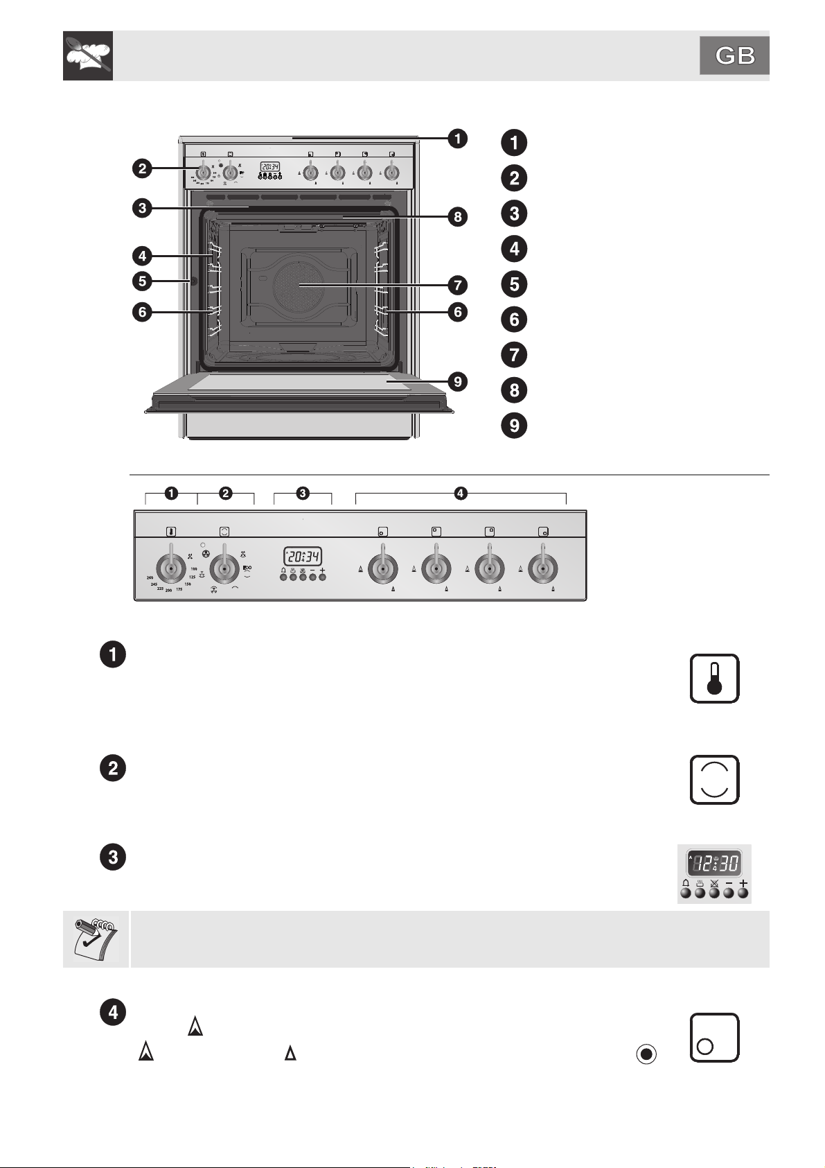
4. GET TO KNOW YOUR APPLIANCE
Cooking hob
Control panel
Oven seal
Oven light (double on some models)
Door sensor (on some models only)
Rack/tray support frame/guide
Fan
Roof liner (on some models only)
Door
4.1 Description of the controls on the front panel
4.1.1 Temperature selection knob
The cooking temperature is selected by turning the knob clockwise to the required
setting, between 50° and 260°C. The indicator light comes on to indicate that the oven
is heating up. When this light goes out, the preset heating temperature has been
reached. When the light flashes regularly, it means that the temperature inside the
oven is kept steady on the set level.
4.1.2 Function selection knob
The oven's various functions are suitable for different cooking modes. After selecting
the required function, set the cooking temperature using the thermostat knob. For
more information on the cooking functions, see: “8. COOKING WITH THE OVEN”.
4.1.3 Programming clock
The programming clock can be used to display the current time or to set a timer or a
programmed cooking operation.
The timer does not stop the cooking operation. It only warns the user that the preset number of minutes
have passed.
4.1.4 Hob burners control knob
To light the flame, press the knob and turn it anti-clockwise to the maximum flame
symbol ( ). To adjust the flame, turn the knob to the zone between the maximum
( ) and the minimum ( ) settings. To turn off the burner, turn the knob to the
position. (The adjacent symbol indicates the front left burner).
9
Page 10
Instructions for the user
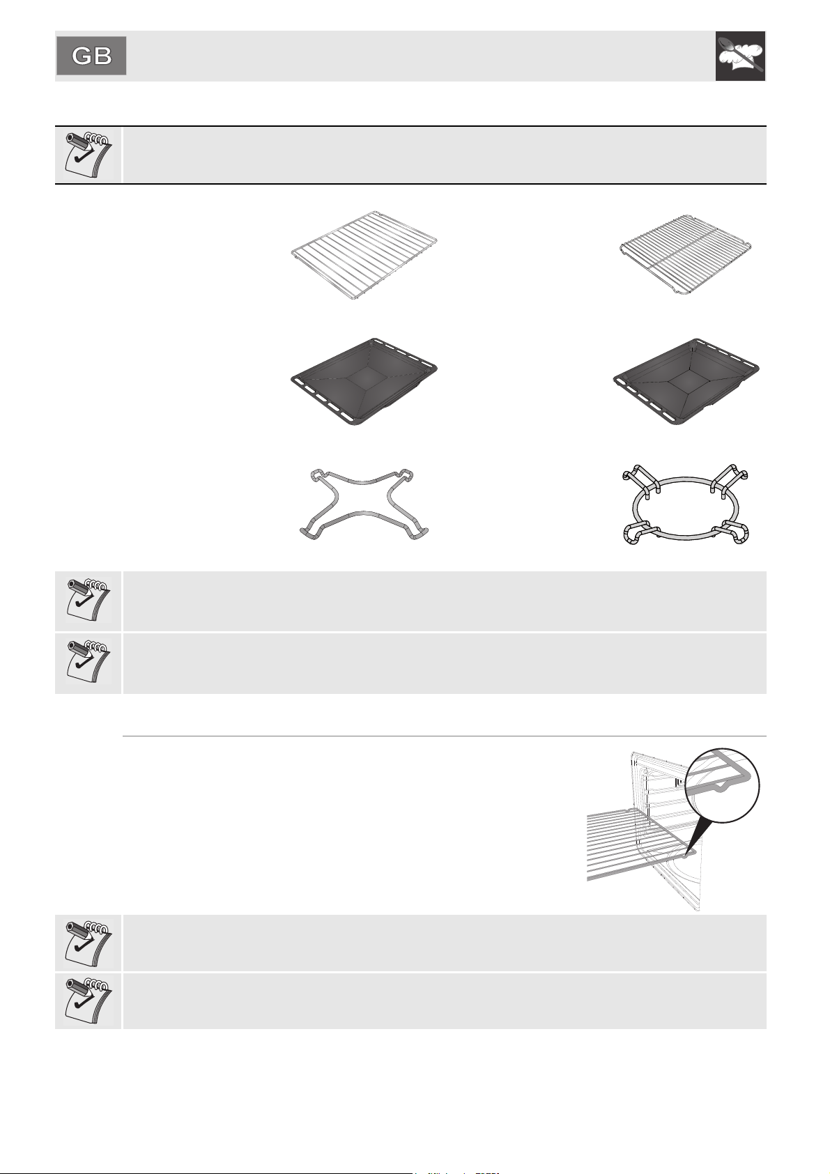
5. AVAILABLE ACCESSORIES
NOTE: Some models are not provided with all accessories.
Rack: useful for holding
cooking containers.
Tray rack: to be placed
over the top of the oven
tray; for cooking foods
which may drip.
Oven tray: useful for
collecting fat from foods
placed on the rack
above.
Reduction pan stand:
useful when using small
pans.
The oven accessories intended to come into contact with food are made of materials that comply with
the provisions of current legislation.
Accessories available on request:
• Original supplied and optional accessories may be ordered from any Authorised Support Centre.
• Use only original accessories supplied by the manufacturer.
Deep oven tray: for
baking cakes, pizza and
oven-baked desserts.
WOK reduction: useful
when using a wok.
5.1 Using the rack or tray
The racks and trays are equipped with a mechanical safety lock which
prevents them from being taken out accidentally. To insert the rack or tray
correctly, check that the lock is facing downwards (as shown in the figure
at the side).
To remove the rack or tray, lift the front slightly.
The mechanical lock (or the extension piece where present) must always
face the back of the oven.
10
Gently insert racks and trays into the oven until they come to a stop.
In models with runners, clean the trays before using them for the first time. Cleaning will remove any
manufacturing residues, which may otherwise scratch the sides of the oven cavity when trays are being
inserted.
Page 11
Instructions for the user
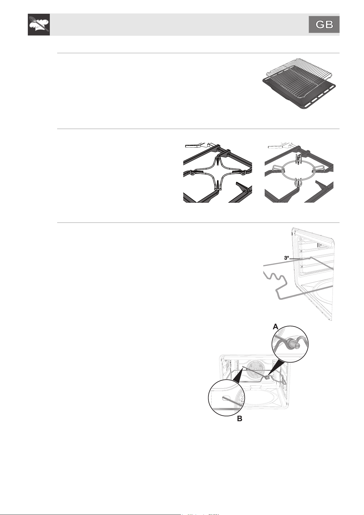
5.2 Using the support rack
The support rack is inserted into the tray (as shown in the figure). Using
this, foods can be cooked and the fat can be collected separately from the
food which is being cooked.
5.3 Using the reduction pan stands
The reduction pan stands should be placed
on top of the hob pan stands as shown in
the adjacent figure. Make sure they are
stable.
The WOK pan stand should only be used
when cooking with a wok.
5.4 Using the rotisserie rod (on some models only)
When cooking with the rotisserie, position the frame on the third runner
(see 7.2 Oven runners). Once the frame is inserted, the shaped part must
sit facing outwards (as shown in the figure).
Then prepare the rotisserie rod with the food, using the clip forks
provided.
So that you can handle the rod with the food on it readily, screw on the
handle provided.
Having prepared the rotisserie rod with the
food, position it on the guide frame as
shown in the figure.
Insert the rod into the hole (detail B) so that
it connects with the rotisserie motor.
Make sure that the pin is placed correctly
on the guide frame (detail A).
11
Page 12

Instructions for the user
6. USING THE COOKING HOB
6.1 General warnings and advice
Before lighting the hob burners, make sure that the flame-spreader crowns are correctly positioned in
their housings with their respective burner caps.
Before lighting the burners lift the glass lid (where present); before closing it again, turn off
all the burners and wait for them to cool.
6.2 Lighting the hob burners
All the appliance's control and monitoring devices are placed together on the
front panel. The burner controlled by each knob is shown next to the knob.
The appliance is equipped with an electronic lighter. Simply press the knob
and turn it anti-clockwise to the maximum flame symbol until the burner
lights. If the burner does not light in the first 15 seconds, turn the knob to “0”
and wait 60 seconds before trying again. After lighting, keep the knob
pressed down for a few seconds to allow the thermocouple to heat up. The
burner may go out when the knob is released: in this case, the thermocouple
has not heated up sufficiently.
Wait a few moments and repeat the operation keeping the knob pressed for
longer.
If the burners should go out accidentally, a safety device will be tripped, cutting off the gas supply, even if
the gas tap is open. In this case, turn the knob to the OFF position and wait at least 60 seconds before
trying to light the burner again.
6.3 Practical hints for using the hob burners
For better burner efficiency and to minimise gas consumption: use pans with
lids and of a suitable size for the burner, so that the flames do not reach up
the sides of the pan (see paragraph “6.4 Pan diameters”). Once the contents
come to the boil, turn down the flame far enough to ensure that the liquid
does not boil over. If any liquid does boil over or spill, remove the excess
from the hob.
To prevent burns or damage to the hob during cooking, all pans or griddles
must be placed inside the perimeter of the hob. All pans must have smooth,
flat bottoms.
If the flame accidentally goes out, turn off the control knob and wait at
least 1 minute before trying to re-light the burner.
Take the greatest care when using fats or oils since they may catch fire if overheated.
12
Page 13

Instructions for the user
6.4 Pan diameters
Burner Ø min. (cm) Ø max. (cm)
Auxiliary 12 14
Semi-rapid 16 24
Ultra-rapid 18 26
To prevent damage to the appliance or adjacent units, all pans or griddles must be placed inside the
perimeter of the hob.
Make sure never to come into contact with the lid glass with pots or pans that are still hot. The glass
could crack and break with the heat.
6.5 Glass lid (on some models only)
The toughened glass lid with aluminium
edging protects the hob when not in use.
Make sure never to come into contact with the lid glass with pots or pans that are still hot. The glass
could crack and break with the heat.
The lid must be raised (open) when the oven or hob is being used. Before lighting the burners lift the
glass lid; before closing it again, turn off all the burners and wait for them to cool.
13
Page 14

Instructions for the user
7. USING THE OVEN
7.1 Before using the appliance
• Remove any labels (apart from the technical data plate) from trays, dripping pans and the cooking
compartment.
• Remove any protective film from the outside or inside of the appliance, including from accessories
such as trays, dripping pans, the pizza plate or the base cover.
• Before using the appliance for the first time, remove all accessories from the oven compartment and
wash them as indicated in “9. CLEANING AND MAINTENANCE”.
Heat the empty appliance to the maximum temperature in order to remove any manufacturing
residues which could affect the food with unpleasant odours.
7.2 Oven runners
The oven features 5 runners for positioning trays and racks at different
heights. The insertion heights are indicated from the bottom upwards (see
figure).
7.3 Storage compartment (on some models only)
The storage compartment is in the bottom of
the cooker. It provides storage space for the
appliance’s metal accessories and must not
be used to store flammable materials, cloths,
paper etc..
Do not open the storage compartment when the oven is on and still hot. The temperatures inside it may
be very high.
7.4 Cooling fan system (on some models only)
The appliance is equipped with a cooling system which comes into operation as soon as a cooking
function starts. The fan causes a steady outflow of air that exits from the rear of the appliance and which
may continue for a brief period of time even after the appliance has been turned off.
7.5 Internal light
The oven light comes on when the door is opened (on some models only) or any function is selected.
14
Page 15

Instructions for the user
7.6 General warnings and advice for use
All cooking operations must be carried out with the door closed. The dissipation of heat may
cause hazards.
During cooking, do not cover the bottom of the oven with aluminium or tin foil and do not place pans or
oven trays on it as this may damage the enamel coating. If you wish to use greaseproof paper, place it so
that it will not interfere with the hot air circulation inside the oven.
For the best cooking results, we recommend placing cookware in the
centre of the rack.
To prevent any steam in the oven from causing problems, open the door in
two stages: keep it half open (5 cm approx.) for 4-5 seconds and then fully
open. To access food, always leave the door open as short a time as
possible to prevent the temperature in the oven from falling and ruining the
food.
To prevent excessive amounts of condensation from forming on the internal glass, hot food should not be
left inside the oven for too long after cooking.
While cooking desserts or vegetables, excessive condensation may form on the glass. In order
to avoid this, open the door very carefully a couple of times while cooking.
To prevent hazardous overheating, the appliance's lid (where present) must always be raised when using
the oven.
Heat the empty appliance to the maximum temperature in order to remove any manufacturing
residues which could affect the food with unpleasant odours.
15
Page 16

Instructions for the user
7.7 Electronic programmer
LIST OF FUNCTIONS
Timer key
End of cooking key
Cooking duration key
Value decrease key
Value increase key
7.7.1 Setting the time
On the first use, or after a power failure, will be flashing on the oven's display. Press the
and keys together, and at the same time press the or keys: this will increase or decrease
the setting by one minute for each pressure.
Press either of the value modification keys to display the current time.
7.7.2 Using the timer
Warning: the timer does not stop the cooking operation. It only warns the user that the preset number of
minutes have passed.
The programmer can also be used as an ordinary timer. Press ; the display will show the numbers
; press and hold and use or to set the required number of minutes. When is
released, the countdown will start and and will appear on the display.
After the timer has been programmed, the display will go back to showing the current time; to display the
remaining time, press .
7.7.3 Stopping the buzzer
The buzzer stops automatically after about seven minutes. It can be deactivated manually by pressing
keys and together.
To switch off the oven, return the knobs to the O setting.
7.7.4 Semi-automatic cooking
Semi-automatic cooking is the function which allows a cooking operation to be started and then ended
after a specific length of time set by the user.
16
Having selected a function, press and hold ; the display will show the numbers ; press and
hold and simultaneously use or to set the cooking time. When is released, the
programmed cooking time will start and the display will show the current time together with and A (to
indicate that a programmed cooking operation has been set).
Page 17

Instructions for the user
7.7.5 Automatic cooking
Automatic cooking is the function which allows a cooking operation to be started at a set time and then
ended after a specific length of time set by the user.
Having selected a function, press and hold ; the display will show the numbers ; press and
hold and simultaneously use or to set the required number of minutes.
Press and the sum of the current time plus the preset cooking time will appear on the display. Press
and hold and simultaneously press or to set the cooking end time.
When is released, the automatic cooking operation will start and the display will show the current
time together with and A (to indicate that a programmed cooking operation has been set).
After making the setting, press the key to view the remaining cooking time; press the key to view
the cooking end time.
7.7.6 End of semi-automatic / automatic cooking
At the end of the cooking time the oven will switch off automatically and simultaneously a buzzer will
start to sound intermittently. After the buzzer has been deactivated, the display will return to show the
current time together with the symbol to indicate that the oven has returned to manual use mode.
7.7.7 Deleting the set data
After having programmed semi-automatic or automatic cooking, the settings can be deleted by pressing
keys and simultaneously. To switch off the oven, return the knobs to O setting. The programmer
will interpret the cancellation of the program as terminating the cooking operation.
7.7.8 Modifying the set data
The set cooking data can be modified at any time by holding down the function key and at the same time
pressing the keys or to change the value.
7.7.9 Adjusting the buzzer volume
The buzzer volume can be set to 3 different levels. When the buzzer is in operation, press to change
the setting.
17
Page 18

Instructions for the user
8. COOKING WITH THE OVEN
The ECO symbol indicates which function gives the least energy consumption.
BOTTOM:
The heat coming just from the bottom allows to complete the cooking of foods that
require a longer basic cooking time, without affecting their browning. Perfect for
cakes, pies, tarts and pizzas. This symbol also includes the cleaning function, see
“9.6 VAPOR CLEAN: assisted oven cleaning (on some models only)”.
STATIC:
As the heat comes from above and below at the same time, this system is particularly
suitable for certain types of food. Traditional cooking, also known as static or thermal
radiation cooking, is suitable for cooking just one dish at a time. Perfect for all types
of roasts, bread and cakes and in any case particularly suitable for fatty meats such
as goose and duck.
GRILL:
The heat coming from the grill element gives perfect grilling results above all for thin
and medium thickness meat and in combination with the rotisserie (where present)
gives the food an even browning at the end of the cooking. Perfect for sausages, ribs
and bacon. This function enables large quantities of food, particularly meat, to be
grilled evenly.
FAN-ASSISTED GRILL:
The air produced by the fan softens the strong heatwave generated by the grill, giving
perfect grilling even to very thick foods. Perfect for large cuts of meat (e.g. shin of
pork). We recommend using the 4
FAN-ASSISTED BOTTOM:
The combination of the fan with just the lower heating element allows cooking to be
completed more rapidly. This system is recommended for sterilising or for finishing off
the cooking of foods which are already well-cooked on the surface, but not inside,
which therefore need a little more heat. Perfect for any type of food.
CIRCULAR:
The combination of the fan and the circular element (incorporated in the rear of the
oven) allows to cook different foods on several levels, as long as they need the same
temperatures and cooking time. Hot air circulation ensures instant and uniform
distribution of heat. It will be possible, for instance, to cook fish, vegetables and
biscuits simultaneously (on different levels) without mixing smells and flavours.
th
runner.
18
Page 19

Instructions for the user
8.1 Cooking advice and instructions
8.1.1 General advice
• We recommend preheating the oven before putting the food in. Place the food in the oven only
once the cooking light is off.
• For cooking on several levels, we recommend using a fan-assisted function to achieve uniform
cooking at all heights.
• In general, it is not possible to shorten the cooking times by increasing the temperature (the food
could be well-cooked on the outside and undercooked on the inside).
• While cooking desserts or vegetables, excessive condensation may form on the glass. In order to
avoid this, open the door very carefully a couple of times while cooking.
• For rapid preheating use a fan-assisted function, then select the required function.
8.1.2 Advice for cooking meat
• Cooking times, especially for meat, vary according to the thickness and quality of the food and to
consumer taste.
• We recommend using a meat thermometer for meat when roasting it. Alternatively, simply press on
the roast with a spoon: if it is hard it is ready, if not, it needs another few minutes cooking.
• •
• •
• •
• •
• •
8.1.3 Advice for cooking desserts and biscuits
• Use dark metal moulds for desserts: they help to absorb the heat better.
• •
• The temperature and the cooking time depend on the quality and consistency of the dough.
• •
• Check whether the dessert is cooked right through: at the end of the cooking time, put a toothpick into
the highest point of the dessert. If the dough does not stick to the toothpick, the dessert is cooked.
• •
• If the dessert collapses when it comes out of the oven, on the next occasion reduce the set
temperature by about 10°C, selecting a longer cooking time if necessary.
8.1.4 Advice for defrosting and proving
• We recommend positioning frozen foods in a lidless container on the first runner of the oven.
• •
• The food must be defrosted without its wrapping.
• •
• Lay out the foodstuffs to be defrosted evenly, not overlapping.
• •
• When defrosting meat, we recommend using a rack positioned on the second runner with the
food on it and a tray positioned on the first runner. In this way, the liquid from the defrosting food
drains away from the food.
• •
• The most delicate parts can be covered with aluminium foil.
• •
• For successful proving, a container of water should be placed in the bottom of the oven.
8.1.5 Advice for cooking with the Grill and the Fan-assisted grill
• Using the Grill function (where present), meat can be grilled even when it is put into the oven
cold; preheating is recommended if you wish to change the effect of the cooking.
•
• With the Fan-assisted grill function , however, we recommend that you preheat the oven before
grilling.
19
Page 20

Instructions for the user
8.2 Cooking process information table
Types of food Weight Function
FIRST COURSES
Runner
position from
the bottom
Temperature
°C
Time
(minutes)
Lasagne 3 kg Static 1 or 2 220 - 230 40 - 50
Oven-baked pasta Static 1 or 2 220 - 230 40
MEAT
Roast veal 1 Kg Fan-assisted static 2 180 - 190 70 - 80
Pork loin 1 Kg Static 2 190 - 200 70 - 80
Shoulder of pork 1 Kg Fan-assisted static 2 180 - 190 90 - 100
Roast rabbit 1 Kg Static 2 190 - 200 70 - 80
Turkey breast 1 Kg Fan-assisted static 2 180 - 190 110 - 120
Roast neck of pork 1 Kg Static 2 190 - 200 190 - 210
Roast chicken 1 Kg Fan-assisted static 2 180 - 190 60 - 70
GRILLED MEATS
1st side 2nd side
Pork chops Fan-assisted grill 4 250 7 - 9 5 - 7
Fillet of pork
Fillet of beef
Liver
Fan-assisted grill
Fan-assisted grill
Fan-assisted grill
3 250 9 - 11 5 - 9
3 250 9 - 11 9 - 11
42502 - 32 - 3
Sausages Fan-assisted grill 3 250 7 -9 5 - 6
Meatballs
ROTISSERIE MEAT (where present)
Chicken Rotisserie grill
Fan-assisted grill
32507 - 95 - 6
On a
250 60 - 70
FISH
Salmon trout 0.7 Kg Circular 2 160 - 170 35 -40
BREAD and FOCACCIA
Pizza Fan-assisted static 1 250 6 - 10
Bread Fan-assisted static 1 190 - 200 25 - 30
Focaccia Fan-assisted static 1 180 - 190 15 - 20
DESSERTS
Ring cake Static 2 170 55 - 60
Fruit tart Fan-assisted static 2 160 30 - 35
Fruit tart Static 2 170 35 - 40
Short pastry Fan-assisted static 1 or 2 160 - 170 20 - 25
Jam tarts Static 2 170 20
Paradise cake Static 1 or 2 170 50 - 60
Paradise cake Fan-assisted static 2 160 50 - 60
Light sponge cake Static 2 150 - 160 50 - 60
Rice pudding Fan-assisted static 2 160 50 - 60
Rice pudding Static 2 170 50 - 60
Croissants Fan-assisted static 2 160 25 - 30
20
The times indicated in the following tables do not include the preheating times and are provided
as a guide only.
Page 21

Instructions for the user
9. CLEANING AND MAINTENANCE
Do not use steam jets for cleaning the appliance. The steam could reach the electronics,
damaging them and causing short-circuits.
WARNING: For your safety, you are advised to wear protective gloves while performing any
cleaning or extraordinary maintenance.
Do not use cleaning products containing chlorine, ammonia or bleach on steel parts or parts with
metallic finishes on the surface (e.g. anodizing, nickel- or chromium-plating).
We recommend the use of cleaning products distributed by the manufacturer.
9.1 Cleaning stainless steel
To keep stainless steel in good condition it should be cleaned regularly after use. Let it cool first.
9.2 Ordinary daily cleaning
To clean and preserve the stainless steel surfaces, always use only specific products that do not contain
abrasives or chlorine-based acids.
How to use: pour the product onto a damp cloth and wipe the surface, rinse thoroughly and dry with a
soft cloth or a microfibre cloth.
9.3 Food stains or residues
Do not use metallic sponges or sharp scrapers as they will damage the surfaces.
Use ordinary non-abrasive products with the aid of wooden or plastic utensils if necessary. Rinse
thoroughly and dry with a soft cloth or a microfibre cloth.
Do not allow residues of sugary foods (such as jam) to set inside the oven. If allowed to set for too long,
they could ruin the enamel covering the inside of the oven.
9.4 Cleaning the cooking hob parts
9.4.1 Glass lid (where present)
If liquids fall on the lid when it is closed, carefully remove them with a cloth before opening it.
For easier cleaning, the lid can be taken off its hinges.
1 Lower the lid to closed position.
2 Unscrew the screws positioned on the back of the two hinges (indicated
for the various models by the arrow in the figure) and lift it upwards.
3 Clean.
4 Insert the lid into the guides. Tighten the fastening screws on the
hinges in closed position.
21
Page 22

Instructions for the user
9.4.2 Pan stands
Remove the pan stands and clean them with lukewarm water and non-abrasive detergent, making sure
to remove any encrustations. Dry them thoroughly and return them to the hob.
Continuous contact between the pan stands and the flame can cause modifications to the enamel over
time in those parts exposed to heat. This is a completely natural phenomenon which has no effect on the
operation of this component.
9.4.3 Burner caps and flame-spreader crowns
The burner caps and flame-spreader crowns can be removed for easier
cleaning. Wash them in warm water and a non-abrasive detergent making
sure to remove any encrustation, then wait until they are perfectly dry.
Refit the flame-spreader crowns, making sure that they are correctly in
place with their respective burner caps, and ensuring that the holes A in
the flame-spreaders are aligned with the igniters and thermocouples.
Do no wash these parts in a dishwasher.
9.4.4 Igniters and thermocouples
For correct operation, the igniters and thermocouples must always be
perfectly clean. Check them frequently and clean them with a damp cloth if
necessary. Remove any dry residues with a wooden toothpick or a needle.
Do not use cleaning products containing chlorine, ammonia or bleach on steel parts or parts with
metallic finishes on the surface (e.g. anodizing, nickel- or chromium-plating).
22
Page 23

Instructions for the user
9.5 Cleaning the oven
For the best oven upkeep, clean it regularly after having
allowed it to cool.
• Take out all removable parts.
• Clean the oven racks with hot water and non-abrasive
detergent. Rinse and dry.
• For easier cleaning, the door can be removed (see
“10.2 Removing the door”).
The oven should be operated at the maximum heat setting for 15/20 minutes after use of specific
products, to burn off the residues left inside the oven.
When the operation is complete, damp parts should be dried thoroughly.
9.5.1 Removing guide frames
Removing the guide frames enables the sides to cleaned
more easily. This should be done each time the automatic
cleaning cycle is used (on some models only).
To remove the guide frames:
1 pull the frame towards the inside of the oven to unhook
it from its housing A, then slide it out of the seats at the
back B.
2 When cleaning is complete, repeat the above
procedures to put the guide frames back in.
9.5.2 Cleaning the door glazing
The glass in the door should always be kept thoroughly clean. Use absorbent kitchen roll; remove
stubborn dirt with a damp sponge and an ordinary detergent.
Do not use abrasive or corrosive detergents to clean the oven's glass doors (e.g. powder products, spotremovers and wire sponges). Do not use rough or abrasive materials or sharp metal scrapers to clean
the oven's glass doors since they may scratch the surface.
9.5.3 Cleaning the door seal
To keep the seal clean, use a non-abrasive sponge and lukewarm water. The seal should be soft and
flexible (with the exception of pyrolitic models).
In pyrolitic models, the seal may flatten over time and lose its original shape. To restore it, pinch the seal
all the way along. This also helps remove any dirt on the seal.
23
Page 24

Instructions for the user
9.6 VAPOR CLEAN: assisted oven cleaning (on some models only)
VAPOR CLEAN is an assisted cleaning procedure which facilitates the removal of dirt. Thanks to this
process, it is possible to clean the inside of the oven with great ease. The dirt residues are softened by
the heat and water vapour for easier removal afterwards.
Before starting the assisted cleaning cycle, make sure that the oven does not contain any foods or large
spills from previous cooking operations.
Carry out assisted oven cleaning operations only when the oven is cold.
9.6.1 Before starting the assisted cleaning cycle
Completely remove all
accessories from inside the
oven. The roof lining can be left
inside the oven (where present).
Do not spray excessive amounts of the water and washing up liquid solution. We recommend spraying
approx. 20 times at the most.
Pour approx. 40 cc of water onto
the floor of the oven (as shown in
the figure). Make sure it does not
overflow out of the cavity.
Spray a water and washing up
liquid solution inside the oven
using a spray nozzle. Aim the
spray towards the oven cavity.
At the end of this process, close
the door and set the cleaning
cycle.
24
Page 25

Instructions for the user
9.6.2 Setting the assisted cleaning cycle
Once the preparations have been made for the assisted cleaning cycle, proceed as follows:
1 Turn the function knob to the symbol and the temperature selection knob to the symbol for
the VAPOR CLEAN function.
2 Set a cooking time of 15 minutes using the electronic programmer.
3 At the end of the assisted cleaning cycle, the timer will deactivate the oven heating elements.
9.6.3 End of the assisted cleaning cycle
The water remaining at the end of the assisted cleaning cycle cannot be left inside the oven for long (for
example overnight).
You are advised to wear a pair of gloves during these processes.
At the end of the cleaning cycle, open the door and wipe away the less stubborn dirt with a microfibre
cloth. Use an anti-scratch sponge with brass filaments on tougher encrustations.
We recommend removing the door as described in “10.2 Removing the door” to facilitate access to
restricted spaces.
For improved hygiene and to avoid food being affected by any unpleasant odours, we recommend that
the oven is dried using a fan function at 160°C for approximately 10 minutes. To set the function, see
“4.1.2 Function selection knob”.
If the VAPOR CLEAN cycle is activated after fatty cooking operations, of meat in particular, it may be
necessary to use an oven cleaning product at the end of the cycle to completely remove any stubborn
residue.
25
Page 26

Instructions for the user
10. EXTRAORDINARY MAINTENANCE
The oven requires periodic minor maintenance or replacement of parts subject to wear, such as gaskets,
light bulbs, etc. Specific instructions for each operation of this kind are given below.
Before any intervention that requires access to live parts, disconnect the appliance from the
power supply.
WARNING: For your safety, you are advised to wear protective gloves while performing any
cleaning or extraordinary maintenance.
10.1 Replacing the light bulb
If a light bulb needs to be replaced because it is worn
or burnt out, remove the guide frames; see “9.5.1
Removing guide frames”.
Then remove the bulb cover using a tool (e.g. a
screwdriver).
Remove the bulb by unscrewing (filament bulbs) or
pulling it (halogen bulbs) in the indicated direction.
Replace the bulb with one of the same type (25W for
filament bulbs or 40W for halogen bulbs).
Do not touch halogen bulbs directly with your fingers, wrap them in insulating material.
10.2 Removing the door
Open the door completely.
Insert a pintle into the hole in the
hinge. Repeat for both hinges.
Grasp the door on both sides
with both hands, lift it forming an
angle of around 30° and remove it.
To reassemble the door, put the
hinges in the relevant slots in the
oven, making sure that grooved
sections C are resting completely
at the base of the slots. Lower
the door and once it is in place
remove the pins from the holes in
the hinges.
26
Page 27

Instructions for the user
10.3 Removing the door seal (not on pyrolitic models)
To permit thorough cleaning of the oven, the door seal may be
removed.
There are fasteners on all four sides to attach it to the edge of
the oven. Pull the edges of the seal outwards to detach the
fasteners. The seal must be replaced when it loses elasticity
and hardens.
10.4 Removing the internal glass panels
The glass in the door should always be kept thoroughly clean. To facilitate cleaning, it is possible to
remove the door (see 10.2 Removing the door) and place it on a canvas, or open it and lock the hinges
in order to extract the glass panels. The glass panels of the door can be completely removed by following
the instructions provided below.
Warning: before removing the glass panels, make sure that at least one of the door's hinges has been
locked in the open position as described in chapter “10.2 Removing the door”. This operation may have
to be repeated during the glass removal process if the door is accidentally freed.
Removing the internal glass panel:
• Remove the internal glass panel by pulling the rear part
gently upwards, following the movement indicated by the
arrows (1).
• Then pull the front of the glass panel upwards (2).
• Doing this detaches the 4 pins attached to the glass from
their slots in the oven door.
Removing the middle glass panels:
• (pyrolitic models) there are two middle glass panels
attached using 4 small locks. Remove the middle panels by
lifting them upwards.
• (other models) an intermediate glass panel may be present;
if so, remove it by lifting it upwards.
Cleaning:
• It is now possible to clean the external glass panel and the
panels removed previously. Use absorbent kitchen roll. In
the case of stubborn dirt, wash with a damp sponge and
neutral detergent.
Replacing the glass panels:
• Replace the panels in the opposite order to which they were
removed.
• Reposition the internal glass panel, taking care to centre
and insert the 4 pins attached to the glass into their slots in
the oven door by applying slight pressure.
27
Page 28

Instructions for the installer
11.INSTALLATION
The appliance connection point shall be accessible with the appliance installed.
11.1 Clearances above and around domestic appliances
Extract from AS5601
REQUIREMENTS
1 Overhead clearances – (Measurement A) Range hoods and exhaust fans shall be installed in
accordance with the manufacturer’s instructions. However, in no case shall the clearance between
the highest part of the hob of the cooking appliance and a range hood be less than 600 mm or, for an
overhead exhaust fan, 750 mm. Any other downward facing combustible surface less than 600 mm
above the highest part of the hob shall be protected for the full width and depth of the cooking surface
area in accordance with Clause 5.12.1.2. However, in no case shall this clearance to any surface be
less than 450 mm.
2 Side clearances – (Measurements B & C) Where B, measured from the periphery of the nearest
burner to any vertical combustible surface, is less than 200 mm, the surface shall be protected in
accordance with Clause 5.12.1.2 to a height C of not less than 150 mm above the hob for the full
dimension (width or depth) of the cooking surface area. Where the cooking appliance is fitted with a
‘splashback’, protection of the rear wall is not required.
3 Additional requirements for Freestanding and Elevated Cooking Appliaces – (Measurements
D & E) Where D, the distance from the periphery of the nearest burner to a horizontal combustible
surface is less than 200 mm, then E shall be 10 mm or more, or the horizontal surface shall be above
the trivet. See insets above.
NOTES
1 Requirement 3 does not apply to a freestanding or elevated cooking appliance which is designed to
prevent flames or the cooking vessels from extending beyond the periphery of the appliance.
2 The ‘cooking surface area’ is defined as that part of the appliance where cooking normally takes
place and does not include those parts of the appliance containing control knobs.
3 For definition of hob, see Clause 1.4.64.
4 For definition of trivet, see Clause 1.4.109.
5 Consideration is to be given to window treatments when located near cooking appliances. See
Clause 5.3.4.
28
11.2 Combustion gas discharge
Combustion gases may be discharged by means of hoods connected to a flue with reliable natural
draught, or a fan extraction system. An effective extraction system requires careful design by an
authorised specialist, and must comply with the regulation distances and positions. After installation, the
engineer must issue a certificate of compliance.
Page 29

Instructions for the installer
11.3 Gas connection
This appliance is suitable for installation with Natural Gas or ULPG
(propane/butane). Refer to page 25 for the relevant burner pressure and
appropriate injector sizes. When the appliance is to be connected to
Natural Gas then the pressure regulator supplied must be fitted to the
gas inlet. A test point (for checking the gas pressure) is supplied either
with the regulator or as a separate fitting in the case of ULPG (propane)
appliances.
Connection of the appliance to the gas supply must be in accordance
with the requirements of AS5601. A ½” BSP connector at the inlet is
recommended and the gas supply line to the appliance must be of
adequate length to allow sufficient withdrawal of appliance for service or
disconnection and be:
1. annealed copper pipe or;
2. flexible hose according to AS/NZ1869 & be at least Class “B”, 10 mm
diameter.
The appliance must be installed with provision to allow the gas to be turned off and disconnected for
servicing and removal of the appliance as required from the gas supply. Before the appliance is operated
make certain all relevant parts are placed in the correct position.
On completion of the installation, the installer MUST check for gas leaks and test each burner
individually for the correct flame. Once all burners have been tested individually, turn all burners on
together. Warranty service calls do not cover these adjustments!
To check the operating pressure of the appliance it is recommended at least 2 large size burners are
used. Ensure appliance is secured to wall when installation is completed.
N.G. The regulator supplied must be fitted to the ½ BSP thread at the rear of the appliance. An approved
manual shut-off valve must be installed. The N.G. regulator must be checked and adjusted to 1.0kPa
after installation.
U.L.P.G. Can be connected to the inlet fitting directly. The pressure must
be checked to ensure it is operating at 2.75kPa. A separate test point
fitting must be installed between the piping & the appliance for the
pressure to be checked to ensure it is operating at 2.75kPa.
Installation with flexible hose must be carried out so that the length of the piping does not exceed 2
metres when fully extended; make sure that the hoses do not come into contact with moving parts and
that they are not crushed in any way.
11.3.1Connection to liquid gas
Use a pressure regulator and make the connection on the gas cylinder following the guidelines set out in
the regulations in force.
Make sure that the supply pressure complies with the values indicated in the paragraph “10.3 Burner
and nozzle characteristics tables”.
11.4 Room ventilation
The room containing the appliance should have a permanent air supply in accordance with the
standards in force. The room where the appliance is installed must have enough air flow needed for the
regular combustion of gas and the necessary air change in the room itself. The hob shall be installed in
rooms with natural ventilation, as required by Standards regulations AS/NZS5601.
11.5 Extraction of the combustion products
The combustion products may be extracted by means of hoods connected to a natural draught chimney
whose efficiency is certain or via forced extraction. An efficient extraction system requires precision
planning by a specialist qualified in this area and must comply with the positions and distances indicated
by the regulations. When the job is complete, the installer must issue a certificate of conformity.
29
Page 30

Instructions for the installer
11.6 Electrical connection
Make sure the voltage and the cross-section of the power supply line match the specifications indicated
on the identification plate positioned on the appliance. Do not remove this plate for any reason. A copy of
the plate is attached to the instructions.
The appliance must be connected to the power supply by a qualified technician.
Before performing any operations, switch off the power supply to the appliance.
The appliance must be connected to earth in compliance with electrical system safety regulations.
Where the appliance is connected to the power grid via a plug and socket, both of these must be of the
same type and connected to the power cable in accordance with the regulations in force. The socket
must be accessible after the appliance has been built in.
NEVER UNPLUG BY PULLING ON THE CABLE.
Should the earthing wire need replacing it must be longer than the current conduction wires so that, if
the plug is torn off the power cable, it is the last to be detached.
Avoid use of adapters and shunts as these could cause overheating and risk of burns.
If a fixed connection is being used, fit the power line with an omnipolar circuit breaker with a contact
opening gap equal to or greater than 3 mm, in an easily accessible position close to the appliance.
The manufacturer declines all responsibility for damage to persons or things caused by nonobservance of the above prescriptions or by interference with any part of the appliance.
APPLIANCE
TYPE
(CM)
60
POSSIBLE CONNECTION
TYPES
220 - 240 V 1N~ 3-pole 3 x 1.5 mm² H05V2V2-F
appliance side
CABLE TYPE
(if not present)
30
• Use H05V2V2-F cables resistant to at least 90°C.
• The values indicated above refer to the cross-section of the internal conductor.
• The tightening torque of the screws of the terminal supply wires must be 1.5 - 2 Nm.
• The aforementioned power cables are sized taking into account the coincidence factor (in compliance
with standard EN 60335-2-6).
Page 31

Instructions for the installer
C
11.7 Positioning the skirt (on some models only)
The skirt must always be positioned and secured correctly on
the appliance.
1 Unscrew the 2 nuts (B) on the back of the worktop.
2 Position the skirt above the worktop, taking care to align
the pins (C ) with the holes (D).
3 Secure the skirt to the worktop by tightening screws (A).
11.8 Positioning and levelling the appliance
After making the electrical and/or gas connections, level the
appliance on the floor by means of its four adjustable feet.
First insert the front feet and then the rear feet.
The appliance must be properly levelled to ensure better
stability. Screw or unscrew the bottom part of the foot until the
appliance is stable and level on the floor.
To prevent possible damage to the appliance, we recommend to screw first the front feet and then the
rear ones.
11.9 Wall mounting brackets (where present)
The fastening system provided must be installed to ensure the appliance is stable. If installed correctly,
this system prevents the appliance tipping over.
1) 2)
Use the adjustable feet to level the appliance at
the required height.
Measure the distance from the index of the
opening to the floor.
31
Page 32

Instructions for the installer
3) 4)
Use the same height on the wall to drill the
holes for fastening the brackets. The distance
between the centres of the holes is given in the
diagram above.
Before tightening the brackets fully to the wall,
check that the index on the brackets is at the
same height as the index on the back of the
appliance. Position the appliance, taking care
that the brackets are correctly inserted.
11.10Wall fixing
1 Attach the chain to the cooker
2 Stretch out the chain attached to the cooker horizontally so that the other end touches the wall.
3 Mark the wall in the position where the hole is to be drilled.
4 Drill the hole, insert a wall plug and attach the chain.
5 Once the chain is in position, push the cooker against the wall and reduce the amount of chain links
to keep the chain tight to prevent any excess movement.
32
Page 33

Instructions for the installer
12. ADAPTATION TO DIFFERENT TYPES OF GAS
BEFORE PERFORMING ANY OPERATIONS, SWITCH OFF THE POWER SUPPLY TO THE
APPLIANCE.
Appliance set for gas: Natural gas at a pressure of 1.0 kPa (see label on product)
In the case of operation with other types of gas, the burner nozzles must be changed and the minimum
flame adjusted on the gas taps.
To change the nozzles, proceed as described in the following paragraphs.
12.1 Replacement of nozzles on the hob
1 Remove the pan stands, and remove all the burner
caps and flame-spreader crowns to access the burner
casings.
2 Unscrew the nozzles using a 7 mm socket wrench.
3 Replace the burner nozzles according to the type of gas
to be used (see 12.3 Burner and nozzle characteristics
table).
4 Replace the burners in the correct position.
12.2 Arrangement of burners
Burner
Auxiliary
Semi-rapid
Ultra-rapid
33
Page 34

Instructions for the installer
914774951/ A
12.3 Burner and nozzle characteristics table
Burner ULPG - 2.75 kPa
Nominal gas consumption
(MJ/h)
Auxiliary 3.9 54
Semi-rapid 6.3 68
Ultra-rapid 15.0 105
Burner NG - 1.0 kPa
Nominal gas consumption
(MJ/h)
Auxiliary 3.9 90
Semi-rapid 7.5 120
Ultra-rapid 15 175
Injector
(1/100 mm)
Injector
(1/100 mm)
12.4 Final operations
After replacing the nozzles, reposition the flame-spreader crowns, the burner caps and the pan stands.
Following adjustment to a gas other than the one originally set in the factory, replace the gas setting
label fixed to the appliance with the one corresponding to the new gas. The label is inserted inside the
nozzle pack (where present).
12.4.1Adjusting the hob burner minimum for city or natural gas
Light the burner and turn it to the minimum position.
Extract the gas tap knob and turn the adjustment screw
next to the tap rod (depending on the model) until the
correct minimum flame is achieved.
Refit the knob and verify that the burner flame is stable
(when turning the knob rapidly from the maximum to the
minimum position the flame must not go out). Repeat the
operation on all the gas taps.
12.4.2Adjusting the hob burner minimum for LPG gas
In order to adjust the minimum setting with liquid gas, the screw at the side of the tap rod must be
tightened clockwise all the way.
34
Page 35

The manufacturer reserves the right to make any changes deemed useful for improvement of his products without prior notice.
The illustrations and descriptions contained in this manual are therefore not binding and are merely indicative.
Page 36

Space for rating plate
914774951/ A
 Loading...