

Page 1
EN - ADU - PERISTALTIC PUMP
1
Installation, maintenance and any repairs must be carried out by SMEG authorised staff.
In the event that the device is used in breach of the instructions provided by SMEG, the
manufacturer, the relative warranty rights could be forfeited.
19 510 0599 02
22/04/2013
Ed.
Date
ADU
INSTRUCTION SHEET FOR THE INSTALLATION
DETERGENTS PERISTALTIC PUMP
READ THE MANUAL WITH CARE
This manual relates to the Smeg “ADU” accessory.
The accessory may only be installed on Smeg devices.
For proper, safe use, this manual must be used together wi th the manual of the instrument or glassware
washer on which the accessory is installed.
Failure to read, any misunderstanding or incorrect interpretation of the instructions provided in this manual
may lead to misuse of the appliance, put the operator at risk and considerably reduce the appliance’s
performance.
The manufacturer declines all liability for uses other than those described in this manual.
The information in this manual is provided for guidance only. The contents and the equipment described
may be subject to change without notice.
INFORMATION AND AFTER-SALES SERVICE
FOR SMEG INSTRUMENTS DIVISION PRODUCTS
Our Sales Department staff will be able to provide you with information about prices and special offers.
Our After-Sales Department will be able to provide you with guidance about keeping your appliance
functioning correctly and put you in touch with your nearest authorised Service Centre.
instruments@smeg.it – service.instruments@smeg.it
Our whole product offering can be viewed at:
www.smeg-instruments.com
International customers, please contact your local SMEG distributor.
19 510 0599 02
Page 2
EN - ADU - PERISTALTIC PUMP
2
MACHINE MODEL
DEFAULT FITTED PUMPS
POSSIBLE ADU ACCESSORY
FUNCTIONS
GW3060
P2
P1, P3, P4
GW4090
P1, P2
P3, P4
GW2045
P2
P1
CONTENTS
1. CONTENTS OF PACKAGE ............................................................................................................................ 2
2. ADU INSTALLATION POSITION ................................................................................................................... 3
2.1. GW3060 .................................................................................................................................................. 3
2.2. GW4090 .................................................................................................................................................. 4
2.3. GW2045 .................................................................................................................................................. 4
3. NOZZLE FOR DETERGENTS INLET IN THE CHAMBER ................................................................................. 5
3.1. GW3060 .................................................................................................................................................. 5
3.1.1. GW3060 Old Series: ......................................................................................................................... 5
3.1.2. GW3060 New Series ......................................................................................................................... 5
3.2. GW4090 .................................................................................................................................................. 6
3.2.1. GW 4090 Old Series:......................................................................................................................... 6
3.2.2. GW4090 New Series ......................................................................................................................... 6
3.3. GW2045 .................................................................................................................................................. 7
4. DIP TUBE AND SUPPORT ............................................................................................................................ 7
INSTALLATION INSTRUCTIONS
1. CONTENTS OF PACKAGE
1. N. 1 Peristaltic pump.
2. N. 3 screws and N. 3 washers for pump fastening.
3. Transparent "braided" rubber tube, 2 meters (for the connection between the pump and the
washing chamber and between the pump and the detergent tank).
4. Silicone tube, to connect the pump to the detergent inlet in chamber (only for the GW2045 series).
5. Fastening clamps for the hose.
6. Cable gland ring: applied on the metal frame prevents that the rubber hose is damaged by the
presence of any metal burrs.
7. Steel dip tube: to suck the detergent in the tank.
8. Dip tube support, plastic cylindrical element for the correct positioning of the dip tube into the
tank.
9. Steel nozzle, for placing the detergent in the chamber.
10. Labels P1, P2, P3, P4. Depending on the functionality selected for the pump and the connections
made, use the correct label, briefly:
a. P1: alkaline detergent.
b. P2: acid neutralizing agent.
c. P3: caustic soda.
d. P4: antifoam.
Machine models that can mount the optional ADU pump:
19 510 0599 02
Page 3
EN - ADU - PERISTALTIC PUMP
3
CAUTION
It is very important that the label (P1, P2, P3 or P4) applied to the pump and to the dip
tube is consistent with the selected function.
Any detergent suction errors may affect the washing effectiveness and the appliance
operation.
COMMON NOTES
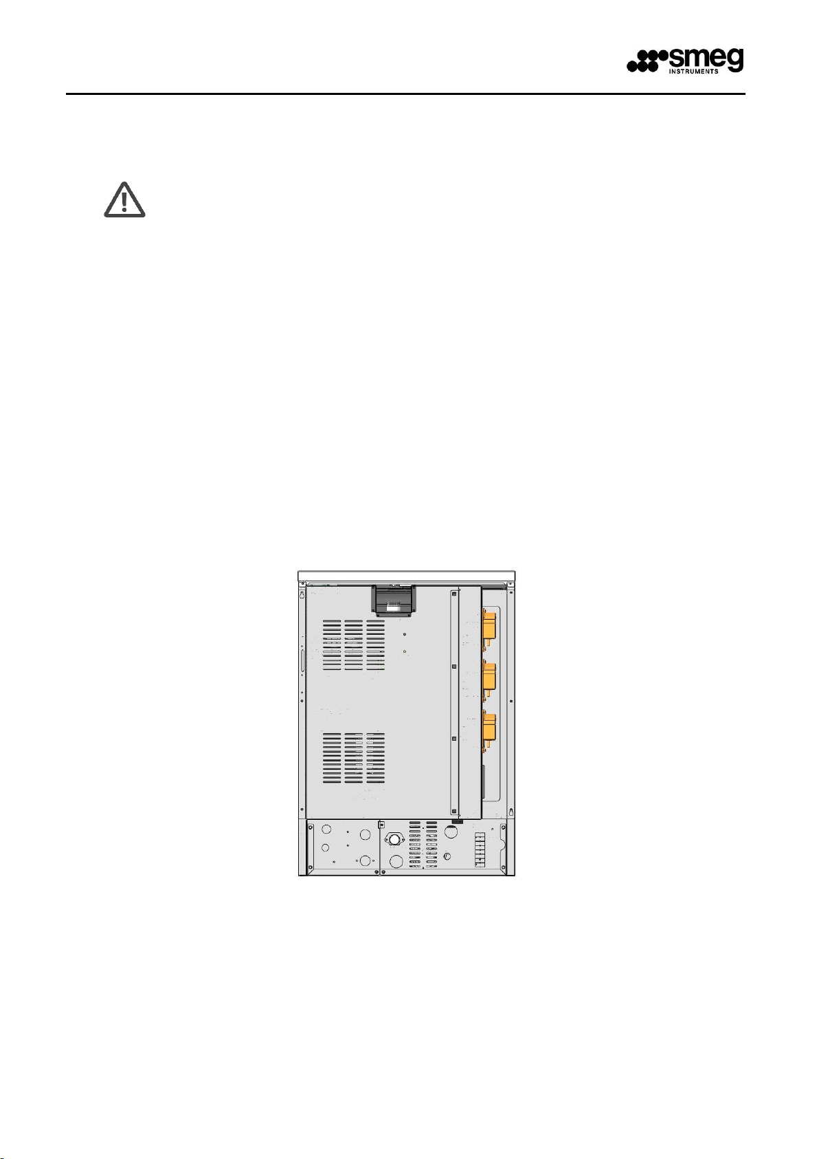
2. ADU INSTALLATION POSITION
2.1. GW3060
The ADU pump must be mounted on the back, in the empty space in the vicinity of the P2 pump. Upper
position for P1, lower for P3 and P4.
The metal back of the machine is divided into two sections, watching from behind: left and right. The two
sections can be easily separated (they are fixed by cross screws and inserted at 1/4 turn and can be opened
with a flat blade screwdriver).
The right section is the one that houses the peristaltic pumps. To install the ADU pump it is necessary to
remove the pre-cut shapes on the frame. On the back of the shapes are the terminals for the electrical
connection of the pumps.
fig. 1 – 3060 back, pumps position from top to bottom, respectively: P1, P2, P3.
19 510 0599 02
Page 4

EN - ADU - PERISTALTIC PUMP
4
2.2. GW4090
The ADU pump must be installed on the peristaltic pumps casing, inside the detergents cabinet, to the right
of the machine, in the free compartment under the P1 and P2 pumps. Left position for P3, right for P4. To
install the ADU pump it is necessary to remove the pre-cut shapes on the frame. On the back of the shapes
are the terminals for the electrical connection of the pumps.
fig. 2 – GW4090, the peristaltic pumps for detergents are housed in the right cabinet.
2.3. GW2045
The ADU pump must be assembled to the rear low panel (or “crossbeam”).
To install the ADU pump it is necessary to remove the pre-cut shapes on the rear crossbeam.
Remove the pre-cut shape, which covers the pre-assembled electric wiring. Cut the plastic tie and use the
wiring to connect the pump.
fig. 3 – GW2045, pumps are located on the rear crossbeam. Rear view: P1 is on the left.
19 510 0599 02
Page 5

EN - ADU - PERISTALTIC PUMP
5
3. NOZZLE FOR DETERGENTS INLET IN THE CHAMBER
3.1. GW3060
After removing the back of the machine you have access to point in which positioning the detergents nozzle
associated with the ADU pump.
3.1.1. GW3060 Old Series
The nozzle is threaded M8 and must be installed in place of one of the stainless steel caps on the
detergents inlet tap. Use liquid Teflon on the thread to improve the tightness of the component.
fig. 4 – GW3060, removing the back you have access to the point in which the stainless steel nozzle for detergent inlet must be installed..
3.1.2. GW3060 New Series
The detergent entrance into the chamber is made by a heat resistant plastic connector located on the rear
of the chamber. The application of the new pump requires the drilling of the nozzle to be used, with a drill
bit Ø 3, 5mm.
fig. 5 – GW3060 detergents inlet connection located on the back of the chamber.
19 510 0599 02
Page 6

EN - ADU - PERISTALTIC PUMP
6
3.2. GW4090
On GW4090 models the detergents inlet nozzles are:
- on the airbreak for the old series, and
- on the back of the chamber for the new series.
After removing the back panel of the machine, proceed as follows.
3.2.1. GW 4090 Old Series
The detergent entrances to the Air-Break need to be drilled directly on the machine (see below). The drill
diameter is 3,5 mm.
fig. 6 – GW4090, Right view, the inlet point of detergents is highlighted. The image to the right shows the airbreak detail that integrates the
nozzles for the detergents inlet.
3.2.2. GW4090 New Series
The detergent entrance into the chamber is made by a heat resistant plastic connector located on the rear
of the chamber. The application of the new pump requires the drilling of the nozzle to be used, with a drill
bit Ø 3, 5mm.
fig. 7 – GW4090, detergents inlet connection is located on the back of the tank
19 510 0599 02
Page 7

EN - ADU - PERISTALTIC PUMP
7
3.3. GW2045
After removing the rear panel of the machine you gain access to the nozzle inlet used to connect the pump
ADU.
The application of the pump must be combined with the removal of the screw, on the nozzles inlet, located
inside the chamber.
fig. 8 – GW2045, The inlet connection detergents is located on the back of the chamber
4. DIP TUBE AND SUPPORT
The following image shows the steel dip tube and how to position the rubber plug.
The rubber plug should be lowered to completely close the opening of the tank detergent.
fig. 9 – Pick-up tube of stainless steel and rubber coupling for detergents suction from the tank.
19 510 0599 02
 Loading...