


Air Cylinder
New
New
ø20, ø25, ø32, ø40, ø50, ø63, ø80, ø100
Female rod end
available as
standard
Selectable
Rod end styles
suitable for the
application can
be selected.
Easy fine adjustment of auto switch position
No trunnion mounting female thread
RoHS
Male threadFemale thread
Fine adjustment of the auto switch position
is possible by simply loosening the screw
attached to the auto switch.
Transparent switch bracket improves
visibility of indicator LED.
Fine adjustment of auto switch
LED colour indicator
Screw attached to auto switch Switch bracket
added to basic type variation
No foreign matter accumulation due
to the simple construction
No trunnion mounting female thread
Series/Made to Order set additionallySeries/Made to Order set additionally
¡
Standard type: Double rod, Single acting ¡Non-rotating type
¡
Direct mount type ¡Made to Order: Heat resistant cylinder
(-XB6), Made of stainless steel (-XC6) and Dual stroke cylinder
(-XC10, 11) etc. are added.
Series CG1
CAT.EUS20-224B-UK

Air Cylinder
Part numbers with rod end bracket and/or pivot bracket available
Not necessary to order a bracket for the applicable cylinder separately
Note) Mounting bracket is shipped together with the product, but not assembled.
Example)
Pivot bracket
— None
Pivot bracket is
shipped together
N
with the product,
but not assembled.
∗ Applicable to only mounting D,
U and T.
CDG1 N20-50Z- N W -M9BW
N: Kit of pivot bracket
and clevis
D
Mounting
Kit of pivot bracket
and trunnion
Various mounting bracket options
s3UITABLEMOUNTINGBRACKETSCANBESELECTEDFOR
the installation condition.
s)MPROVEDAMOUNTOFMOUNTINGFREEDOM
Single knuckle joint
Rod trunnion
Basic
Rod end bracket
— None
V
Single knuckle joint
Double knuckle jointW
Head trunnion
Clevis
With rod end bracket
V: Single
knuckle joint
W: Double
knuckle joint
Pivot bracket
Head flange
Axial foot
Double knuckle joint
Rod flange
Axial foot
Basic (No trunnion mounting female thread)
Easy fine adjustment of auto switch position
Fine adjustment of the auto switch set position can be performed by loosening the
auto switch attached screw without loosening the auto switch mounting band.
Operability improved compared with the conventional auto switch set position
adjustment, where the complete switch mounting
band requires loosening.
Switch bracket
Switch holder
Visibility of the indicator
LED improved with the
transparent resin switch bracket
(Standard specification)
Screw attached to auto switch
Auto switch
No environmental hazardous
substances used
Compliant with EU RoHS directive.
Lead free bushing is used as sliding material.
Specifications, performance and
mounting method are same as the
existing product.
Grease is selectable. (Option)
쐌
Grease for food processing equipment (XC85)
쐌
PTFE grease (X446)
Water resistant compact auto
switch now available
쐌
Solid state auto switch D-M9첸A(V)
Features 1
Auto switch mounting screw
Auto switch mounting band

Series CG1
Stroke Variations
Bore size [mm]
20
25
32
40
50
63
80
100
Series Variations
Series CG1-Z
Series
Standard
CG1-Z
Action
Double
acting
Rod
Single rod
Cushion
Rubber
bumper
Air
cushion
Standard stroke
75 100 125 150 200 250 30020 50
Bore size [mm]
20 25 32 40 50 63 80
100
With
rod boot
Variations
Air-hydro
Clean
series
[mm]
Page
Page 1
Non-rotating rod
CG1K-Z
Direct mount
CG1R-Z
Series CG1
Direct mount,
Non-rotating rod
CG1KR
With end lock
CBG1
Double
acting
Single
acting
Double
acting
Double
acting
Double
acting
Double
acting
Double
acting
Rubber
bumper
Double rod
Air
cushion
Single rod
(Spring return
Single rod
Double rod
Single rod
Single rod
Single rod
/extend)
Rubber
bumper
Rubber
bumper
Air
cushion
Rubber
bumper
Rubber
bumper
Air
cushion
Rubber
bumper
Rubber
bumper
Air
cushion
Page 18
Page 25
Page 30
Page 34
Page 38
www.smc.eu
Short type
Standard
CG3
Series CG3
Double
acting
Single rod
Rubber
bumper
Features 2

Combinations of Standard Products and Made to Order Specifi cations
Series CG1
: Standard
: Made to Order
: Special product (Please contact SMC for details.)
: Not available
—
Symbol Specifi cations
Standard
Long st
D
CG1쏔-쏔
CG1쏔H
10-
Note 9)
20-
R
CG1쏔
V
XB6
XB7
XB9
XB13
XC4
XC6
XC8
Standard
Long stroke
Built-in magnet
J
With rod boot ø20 to ø100
K
Air-hydro type ø20 to ø63
Clean series ø20 to ø100
Note 8)
Copper
Water resistant ø32 to ø100
Heat resistant cylinder (−10 to 150°C)
Cold resistant cylinder (−40 to 70°C)
Low speed cylinder (10 to 50 mm/s)
Low speed cylinder (5 to 50 mm/s)
With heavy duty scraper ø32 to ø63
Made of stainless steel ø20 to ø100
Adjustable stroke cylinder/
Adjustable extension type
and Fluorine-free ø20 to ø100
Series
Action/
type
Cushion
Page
Applicable bore size
ø20 to ø100
Note 7)
Note 7)
ø20 to ø100
CG1
(Standard type)
Double acting
Single rod Double rod Single rod
Rubber Air Rubber Air Rubber
Page 1 Page 18 Page 25
ø20 to ø100 ø20 to ø40
Single acting
Note 11)
—
Note 11)
Note 1)
Note 11)
Note 11)
——
Note 1)
Note 2)
Note 2)
Note 2)
Note 2) Note 5)
—
—
Note 6)
——
XC9
XC10
XC11
XC12
XC13
XC20
XC22
XC27
XC29
XC35
XC37
XC42
XC85
X446
Note 1) ø40 to ø63 only
Note 2) Without bumper
Note 3) ø32 to ø100 only
Note 4) SV type only (Heat resistant grease is used.)
Note 5) ø20 to ø63 only
Note 6) Single acting/spring return type (S) only
Note 7) The products with an auto switch are not compatible.
Note 8) Copper-free for the externally exposed part
Note 9) For details, refer to www.smc.eu.
Note 10) Long stroke is beyond the performance guarantee.
Note 11) Female rod end is available as a special order.
Adjustable stroke cylinder/
Adjustable retraction type
Dual stroke cylinder/Double rod type
Dual stroke cylinder/Single rod type
Tandem cylinder
Auto switch rail mounting ø20 to ø100
Head cover axial port ø20 to ø63
Fluororubber seal
Double clevis and double knuckle joint
pins made of stainless steel
Double knuckle joint with spring pin
With coil scraper
Larger throttle diameter of connection port
Built-in shock absorber in head cover side
Grease for food processing equipment ø20 to ø100
PTFE grease ø20 to ø100
ø20 to ø63
ø20 to ø100
ø20 to ø63
——
——
——
Note 2) Note 2)
——
Note 5) Note 5)
——
——
Front matter 1

Series CG1
(Non-rotating rod type)
CG1K
Double acting Double acting
Single rod Double rod Single rod
Rubber Air Rubber Rubber Air
Page 30 Page 34 Page 38
ø20 to ø63 ø40 to ø63 ø20 to ø63 ø20 to ø63
CG1R
(Direct mount type)
Note 10)
Note 10)
Note 10)
———
———
—
———
———
———
———
———
———
Note 2)
Note 2)
———
Symbol
Standard
Long st
D
CG1쏔-쏔
CG1쏔H
10-
Note 9)
20-
R
CG1쏔
V
XB6
XB7
XB9
XB13
XC4
XC6
CG1CG1WCG1CG1KCG1KWCG1R
Double Acting, Single RodDouble Acting, Double Rod
StandardNon-rotating RodDirect Mount
J
K
Single Acting, Spring Return/Extend
—
—
—
—
—
Note 2)
———
—
XC8
XC9
XC10
XC11
XC12
XC13
XC20
XC22
XC27
XC29
XC35
XC37
XC42
XC85
X446
Double Acting, Single RodDouble Acting, Double RodDouble Acting, Single Rod
Auto SwitchMade to Order
Front matter 2

Air Cylinder: Standard Type
Double Acting, Single Rod
Series CG1
RoHS
ø20, ø25, ø32, ø40, ø50, ø63, ø80, ø100
How to Order
CG1
With auto switch
CDG1
20NB
20 Z
100
100
Z
With auto switch
(Built-in magnet)
Mounting
B
∗
Basic (without trunnion mounting female thread)
Z
L
F
G
∗
U
∗
T
D
∗ Not available for ø80 or ø100.
∗ Mounting bracket is shipped together with
the product, but not assembled.
∗
The cylinder for F, G, L, D mounting types is Z:
Basic (without trunnion mounting female thread).
Basic
Axial foot
Rod fl ange
Head fl ange
Rod trunnion
Head trunnion
Clevis
Bore size
20
25
32
40
50
63
80
100
Type
Rubber bumper
N
Air cushion
A
20 mm
25 mm
32 mm
40 mm
50 mm
63 mm
80 mm
100 mm
Pivot bracket
—
Pivot bracket is shipped together
N
with the product, but not assembled
∗ Only for D, U, T mounting types
∗ Pivot bracket is shipped together
with the product, but not assembled.
Rod end bracket
—
V
W
∗ No bracket is provided for the female rod end.
∗ Rod end bracket is shipped together with the product, but not assembled.
∗ A knuckle joint pin is not provided with the single knuckle joint.
Port thread type
Air cushion
Rc ø32 to ø100
G ø32 to ø100
Rod end thread
Male rod end
—
Female rod end
F
Cylinder stroke [mm]
Refer to “Standard Strokes” on page 2.
—
TN
TF
Rc ø20 to ø100
NPT ø20 to ø100
M5 x 0.8 ø20, ø25
G ø32 to ø100
Rubber bumper
M5 x 0.8 ø20, ø25
NPT ø32 to ø100
Applicable Auto Switches/Refer to the Auto Switch Guide for further information on auto switches.
Type
∗∗∗
∗ Lead wire length symbols: 0.5 m·················· — (Example) M9NW
1 m·················· M
3 m··················
5 m··················
None
∗ Since there are other applicable auto switches than listed, refer to page 47 for details.
∗ For details about auto switches with pre-wired connector, refer to the Auto Switch Guide.
∗ The D-A9쏔쏔/M9쏔쏔쏔 auto switches are shipped together, (but not assembled). (However, only the auto switch mounting brackets are assembled before shipment.)
Special
function
—
Diagnostic indication
(2-colour indication)
Solid state auto switch
Water resistant
(2-colour indication)
With diagnostic output (2-colour indication)
—
Reed auto switch
Diagnostic indication (2-colour indication)
Water resistant type auto switches can be mounted on the above models, but in such case SMC cannot guarantee the water resistance.
A water-resistant type cylinder is recommended for use in an environment which requires water resistance. However, please contact SMC for water-resistant products of ø20 and ø25.
Electrical
entry
Grommet
Connector
Grommet
Grommet
Connector
Grommet
Wiring
(Output)
Indicator light
3-wire (NPN)
3-wire (PNP)
2-wire 12 V
3-wire (NPN)
Yes
3-wire (PNP)
2-wire 12 V
3-wire (NPN)
3-wire (PNP)
2-wire 12 V
4-wire (NPN)
3-wire (NPN equivalent)
Yes
No
Yes
2-wire 24 V
No
Yes
No
Yes
L
··············· N (Example) H7CN
Z
Load voltage
DC AC
5 V, 12 V
5 V, 12 V
24 V
5 V, 12 V
5 V, 12 V
—5 V —
12 V
—— —
(Example) M9NWM
(Example) M9NWL
(Example) M9NWZ
Perpendicular
—
M9NAV
M9PAV
M9BAV
100 V
100 V or less
100 V, 200 V
200 V or less
——
24 V or less
∗ Solid state auto switches marked with “쑗” are produced upon receipt of order.
Auto switch model
Applicable bore size
ø20 to ø63 ø80, ø100
In-line In-line
M9NV M9N
——
M9PV M9P
——
M9BV M9B
—
H7C
M9NWV M9NW
——
M9PWV M9PW
——
M9BWV M9BW
——
∗∗∗
∗∗∗
∗∗∗
——
—
∗∗∗
M9NA
∗∗∗
M9PA
∗∗∗
M9BA
H7NF G59F
A96V A96
A93V A93
A90V A90
—
—
C73C
—
C80C
B59W
B54
B64
1
V
W
NND
None
Single knuckle joint
Double knuckle joint
—
G59
—
G5P
—
K59
—
—
G59W
—
G5PW
—
K59W
—
—
—
G5BA
—
—
—
—
—
M9BW
None
∗ In the case of w/rod boot, and a foot bracket or
rod fl ange as a bracket, those parts are to be
assembled at the time of shipment.
∗ For female rod end, no rod boot is provided.
Lead wire length [m]
0.5
(—)1[m]3(L)5(Z)
∗∗∗
——
Made to Order
For details, refer to page 2.
Number of auto switches
—
S
n
2 pcs.
1 pc.
“n” pcs.
Auto switch
Without auto switch
—
∗ For applicable auto switches,
refer to the table below.
Suffi x for cylinder (Rod boot)
—
J
K
—
—
—
—
—
—
—
—
——— —
—
——— —
—
——— —
—
—
——— — —
Without rod boot
Nylon tarpaulin
Heat resistant tarpaulin
Pre-wired
connector
None
[N]
—
—
—
—
—
—
—
—
—
—
—
—
—
—
—
—
—
—
—— —
——
—
—
Applicable
load
IC
circuit
———
IC
circuit
—
IC
circuit
—
IC circuit
IC circuit
IC circuit
—
IC circuit
Relay,
PLC
—
Relay,
PLC

Specifi cations
Air Cylinder: Standard Type
Double Acting, Single Rod
Series CG1
Symbol
Rubber bumper
Refer to pages 42 to 47 for cylinders with
auto switches.
· Auto switch proper mounting position
(detection at stroke end) and its mounting
height
· Minimum stroke for auto switch mounting
· Operating range
· Auto switch mounting brackets/Part no.
Air cushion
Made to Order
(For details, refer to pages 49 to 65.)
Symbol Specifi cations
Change of rod end shape
-XA쏔
Heat resistant cylinder (–10 to 150°C)
-XB6
Cold resistant cylinder (–40 to 70°C)
-XB7
Low speed cylinder (10 to 50 mm/s)
-XB9
Low speed cylinder (5 to 50 mm/s)
-XB13
With heavy duty scraper
-XC4
Made of stainless steel
-XC6
Adjustable stroke cylinder/Adjustable extension type
-XC8
Adjustable stroke cylinder/Adjustable retraction type
-XC9
Dual stroke cylinder/Double rod type
-XC10
Dual stroke cylinder/Single rod type
-XC11
Tandem cylinder
-XC12
Auto switch rail mounting
-XC13
Head cover axial port
-XC20
Fluororubber seal
-XC22
Double clevis and double knuckle joint pins made of stainless steel
-XC27
Double knuckle joint with spring pin
-XC29
With coil scraper
-XC35
Larger throttle diameter of connection port
-XC37
Built-in shock absorber in head cover side
-XC42
Grease for food processing equipment
-XC85
PTFE grease
-X446
3
∗
3
∗
1
∗
3
∗
∗1 Cylinders with rubber bumper have no bumper.
∗2 Only compatible with cylinders with rubber
bumper, but has no bumper.
∗3 Only compatible with cylinders with rubber
bumper.
1
∗
2
∗
3
∗
3
∗
∗3
3
∗
Bore size [mm]
Action Double acting, Single rod
Lubricant Not required (Non-lube)
20 25 32 40 50 63 80 100
CG1CG1WCG1CG1KCG1KWCG1R
Fluid Air
Proof pressure 1.5 MPa
Maximum operating pressure
Minimum operating pressure
Ambient and fl uid
temperature
Without auto switch:
With auto switch : –10°C to 60°C
Piston speed 50 to 1000 mm/s
Stroke length tolerance
Up to 1000 st
1.0 MPa
0.05 MPa
–
10°C to 70°C
+1.4
mm, Up to 1500 st
0
(No freezing)
50
to
+1.8
mm
0
700 mm/s
Double Acting, Single RodDouble Acting, Double Rod
StandardNon-rotating RodDirect Mount
Cushion Rubber bumper, Air cushion
Mounting
∗∗
Basic, Basic (without trunnion mounting female thread),
Axial foot, Rod fl ange, Head fl ange, Rod trunnion, Head
trunnion, Clevis (used for changing the port location by 90°)
Allowable
kinetic
energy
(J)
Rubber
bumper
Air
cushion
Male
rod end
Female
rod end
Male
rod end
Female
rod end
0.28 0.41 0.66 1.20 2.00 3.40 5.90 9.90
0.11 0.18 0.29 0.52 0.91 1.54 2.71 4.54
R: 0.35
H: 0.42
R: 0.56
H: 0.65
0.91 1.80 3.40 4.90 11.80 16.70
0.11 0.18 0.29 0.52 0.91 1.54 2.71 4.54
Single Acting, Spring Return/Extend
∗ R: Rod side, H: Head side
∗∗ Cylinder sizes ø80 and ø100 do not have basic (without trunnion mounting female thread), rod
trunnion and head trunnion types. Foot, fl ange and clevis types of cylinder sizes from ø20 to
ø63 do not have trunnion mounting female thread. Operate the cylinder within the allowable
kinetic energy.
Double Acting, Single RodDouble Acting, Double RodDouble Acting, Single Rod
Accessories
Axial
Rod
Mounting Basic
Standard
∗3
∗3
Option
Rod end nut
Clevis pin — — — — — —
Single knuckle joint
Double knuckle joint
∗∗
(with pin)
Pivot bracket
∗
Rod boot
foot
————
fl ange
Head
fl ange
Rod
trunnion
∗
Head
trunnion
∗
Clevis
∗ Not available for ø80 and ø100.
∗∗ A double knuckle joint pin and retaining rings are shipped together.
Standard Strokes
Bore size [mm]
∗3
20
25
Standard stroke [mm]
25, 50, 75, 100, 125, 150, 200 201 to 1500
Note1)
Long stroke [mm]
32
40
50, 63
25, 50, 75, 100, 125,
150, 200, 250, 300
301 to 1500
80
100
Note 1) Intermediate strokes not listed above are produced upon receipt of order. Manufacture of
intermediate strokes at 1 mm intervals is possible. (Spacers are not used.)
Note 2) The long stroke shows the maximum manufacturable stroke. For details about maximum
stroke that can be used for each mounting bracket, contact SMC.
Note 2)
Auto SwitchMade to Order
2

Series CG1
Ordering Example of Cylinder Assembly
Cylinder model: CDG1DN20-100Z-NW-M9BW
Auto switch
Clevis
Rod Boot Material
Symbol Rod boot mater
J
K
∗ Maximum ambient temperature for the rod
Mounting D: Clevis
Pivot bracket N: Yes
Rod end bracket W: Double knuckle joint
Auto switch D-M9BW: 2 pcs.
∗ Pivot bracket, double knuckle joint and auto
switch are shipped together with the product, but
not assembled.
Pivot bracket
Double knuckle joint
boot itself.
Mounting Brackets/Part No.
Mounting
bracket
Axial foot 2
Order
q’ty
Note 1)
20 25 32 40 50 63 80 100
CG-L020 CG-L025 CG-L032 CG-L040 CG-L050 CG-L063 CG-L080 CG-L100
Flange 1 CG-F020 CG-F025 CG-F032 CG-F040 CG-F050 CG-F063 CG-F080 CG-F100
Trunnion pin 1 CG-T020 CG-T025 CG-T032 CG-T040 CG-T050 CG-T063 — —
Clevis 1 CG-D020 CG-D025 CG-D032 CG-D040 CG-D050 CG-D063 CG-D080 CG-D100
Pivot bracket
Note 2)
1
CG-020-24A CG-025-24A CG-032-24A CG-040-24A CG-050-24A CG-063-24A CG-080-24A CG-100-24A
Note 1) Order two foots per cylinder.
Note 2) Can be combined with the trunnion pin and the clevis.
Bore size [mm]
Mounting Brackets, Accessories/Material, Surface Treatment
Maximum operating
temperature
Nylon tarpaulin 70°C
Heat resistant tarpaulin
Contents
2 foots,
8 mounting bolts
1 fl ange,
4 mounting bolts
2 trunnion pins, 2 trunnion bolts,
2 fl at washers
1 clevis, 4 mounting bolts,
1 clevis pin, 2 retaining rings
1 pivot bracket
110°C
∗
Segment Description Material Surface treatment
Foot Carbon steel Nickel plating
Carbon steel (ø20 to ø63) Nickel plating
Cast iron (ø80, ø100) Nickel plating
Carbon steel (ø20 to ø63) Nickel plating
Cast iron (ø80, ø100) Nickel plating
Mounting
brackets
Flange
Clevis
Trunnion pin Carbon steel Salt-bath nitrocarburising
Trunnion pin
Trunnion bolt Carbon steel Nickel plating
Flat washer Carbon steel Nickel plating
Rod end nut Carbon steel Zinc chromated
Carbon steel (ø20 to ø32) Nickel plating
Cast iron (ø40 to ø100) Zinc chromated
Carbon steel (ø20 to ø32) Nickel plating
Cast iron (ø40 to ø100) Zinc chromated
Accessories
Single knuckle joint
Double knuckle joint
Knuckle pin Carbon steel —
Clevis pin Carbon steel —
Pivot bracket
Carbon steel (ø20 to ø63) Nickel plating
Cast iron (ø80, ø100) Nickel plating
Mounting bolt Carbon steel Nickel plating
Retaining ring Carbon tool steel Phosphate coating
Mounting Procedure
Mounting procedure for trunnion
Follow the procedures below when mounting a
pivot bracket on the trunnion.
Cylinder body
Trunnion bolt (With
scotch grip) 4 or 5
times remounting
possible
Flat washer
(Put grease on the exterior.)
Pivot bracket
Trunnion pin
Mounting procedure for clevis
Follow the procedures below when mounting a pivot bracket on the clevis.
Retaining
ring
Clevis pin
(Put grease)
Cylinder body
Pivot bracket
Retaining
ring
ø80, ø100ø20 to ø63ø20 to ø63
Retaining
ring
Clevis pin
(Put grease)
Cylinder
body
Pivot bracket
Retaining
ring
3

Air Cylinder: Standard Type
Double Acting, Single Rod
Series CG1
Weights
Bore size [mm]
Basic (B) 0.11 0.17 0.24 0.44 0.79 1.06 2.07 3.16
Basic (Z) 0.11 0.17 0.25 0.45 0.80 1.09 — —
Axial foot 0.21 0.29 0.40 0.67 1.26 1.77 3.04 4.91
Flange 0.18 0.26 0.38 0.65 1.16 1.64 2.78 4.44
Basic weight
Pivot bracket 0.08 0.09 0.17 0.25 0.44 0.80 0.98 1.75
Single knuckle joint 0.05 0.09 0.09 0.10 0.22 0.22 0.39 0.57
Double knuckle joint (with pin) 0.05 0.09 0.09 0.13 0.26 0.26 0.64 1.31
Additional weight per 50 mm of stroke 0.05 0.07 0.09 0.14 0.21 0.25 0.35 0.50
Additional weight for switch magnet 0.01 0.01 0.01 0.01 0.01 0.02 0.02 0.04
Additional weight with air cushion 0 0.01 0.04 0 0.01 0.04 0 0.04
Weight reduction for female rod end −0.01 −0.02 −0.02 −0.05 −0.10 −0.10 −0.19 −0.27
Trunnion 0.12 0.19 0.28 0.49 0.88 1.20 — —
Clevis 0.17 0.25 0.39 0.68 1.19 1.78 2.77 4.44
Calculation (Example) CDG1FN20-100Z
(Built-in magnet, Flange, ø20, 100 stroke)
20 25 32 40 50 63 80 100
¡Basic weight ··········································0.18 kg (Flange, ø20)
¡Additional weight for stroke ···················0.05 kg/ 50 mm
¡Air cylinder stroke ·································100 mm
¡Additional weight for switch magnet ······0.01 kg
0.18 + 0.05 x (100/50) + 0.01 = 0.29 kg
[kg]
CG1CG1WCG1CG1KCG1KWCG1R
Double Acting, Single RodDouble Acting, Double Rod
StandardNon-rotating RodDirect Mount
Weights of Cylinder Movable Parts
Bore size [mm]
Male rod end 40.0 68.5 96.0
Female rod end 30.9 51.7 77.0
20 25 32 40 50 63 80 100
209.7 379.1 409.7 827.8
161.0 282.0 312.5 637.4
[g]
1259.7
991.5
Additional Weights
Bore size [mm]
Additional weight per 50 mm of stroke
Switch magnet
∗
Do not apply a lateral load over the allowable range to the rod end when it is mounted horizontally.
Standard weight of movable parts
Calculation (Example) CDG1BN40-150Z (Built-in magnet, Basic, ø40, 150 stroke)
¡
Standard weight of movable parts: Male rod end, Bore size [40] ··············209.7 g
¡
Additional weight: Additional weight of stroke
¡
Switch magnet ·····························································································12.6 g
Total 457.5 g
Clean Series Air-hydro
N10-CG1
Mounting style
Clean Series (With relief port)
The type which is applicable for using inside the clean room graded Class
100 by making an actuator’s rod section a double seal construction and
discharging by relief port directly to the outside of clean room.
Bore size
Stroke
Specifi cations
Bore size [mm]
Action Double acting
Fluid Air
Maximum operating pressure 1.0 MPa
Minimum operating pressure 0.05 MPa
Cushion Rubber bumper
Piston speed 30 to 400 mm/s
Relief port size M5 x 0.8
Mounting
∗ Auto switch can be mounted.
∗∗ The basic type is B type only. However, no trunnion mounting female
thread is provided.
20, 25, 32, 40, 50, 63, 80, 100
Basic, Axial foot, Rod fl ange,
Head fl ange
∗∗
Z
Mounting style
Low pressure hydraulic cylinder of 1.0 MPa or less
When using together with the CC series air-hydro unit, constant and low
speed actuation and intermediate stopping similar to hydraulic units are
possible with the use of valves and other pneumatic equipment.
Specifi cations
Bore size [mm]
Action Double acting
Fluid Turbine oil
Proof pressure 1.5 MPa
Maximum operating pressure 1.0 MPa
Minimum operating pressure 0.18 MPa
Piston speed 15 to 300 mm/s
Cushion None
Ambient and fl uid temperature
Mounting
∗ Auto switch can be mounted.
20 25 32 40 50 63 80 100
19.6 30.6 44.1 78.4
3.5 4.0 9.0 12.6
78.4 x 150/50 = 235.2 g ····235.2 g
HCG1
Bore size
Air-hydro
122.5 122.5 191.4 275.7
14.0 22.0 24.0 35.0
Stroke
Z
20, 25, 32, 40, 50, 63
5 to 60°C
Basic, Axial foot, Rod fl ange, Head
fl ange, Rod trunnion, Head trunnion,
Clevis (used for changing the port
location by 90°)
[g]
Single Acting, Spring Return/Extend
Double Acting, Single RodDouble Acting, Double RodDouble Acting, Single Rod
Auto SwitchMade to Order
S + Stroke
ZZ + Stroke
∗ Other dimensions are the same as the
double acting, single rod, standard type.
TB
Bore size
[mm]
20
25
32
40
50
63
GB TB S ZZ
12 11 77 114
12 11 77 119
12 11 79 121
13 12 87 139
14 13 102 162
14 13 102 162
4

Series CG1
Water Resistant
Bore size
Mounting style
CDG1 Z
Type
Port thread type
R
Stroke
H7BAL
-XC6
With auto switch
(Built-in magnet)
Water resistant cylinder
NBR seals (Nitrile rubber)
R
FKM seals (Fluororubber)
V
Caution
Since the scraper is press-fi t
into the rod cover, it cannot
be replaced.
Water resistant 2-colour
indication, solid state auto switch
H7BAL ø32 to ø63
G5BAL ø80, ø100
Made to Order
Applicable for use in an environment with water splashing
such as food processing and car wash equipment, etc.
Specifi cations
Bore size [mm]
Action Double acting, Single rod
Cushion Rubber bumper/Air cushion
Auto switch mounting Band mounting type
Made to Order
∗ Specifi cations other than above are the same as standard, basic type.
32, 40, 50, 63, 80, 100
XC6: Made of stainless steel
Dimensions
With rubber bumper
GBGA
(E1)
(F1)
TA
S + Stroke F
ZZ + Stroke
With air cushion
(E1)
Bore size
32
40
50
63
80
100
∗ Other dimensions are the same as the double acting single rod standard type.
∗ ( ): Denotes the dimensions for long stroke.
WA
(F1)
S + Stroke F
ZZ
+ Stroke
∗
(E1)
E
17 18 2 2 18 77 (85) 17 22
21 25 2 2 19 84 (93) 18 23
26 30 2 2 21 97 (109) 20 25
26 32 2 2 21 97 (109) 20 25
32 40 3 3 28 116 (130) — 32
37 50 3 3 29 117 (131)
(F1)
∗
GA S TA WA ZZ
F
TB
GBGA
TBTA
0
−0.05
E
ø
0
−0.05
øE
—33
[mm]
119 (127)
136 (145)
157 (169)
157 (169)
190 (204)
191 (205)
Precautions
Be sure to read before handling. Refer to back cover
for Safety Instructions. For Actuator and Auto Switch
Precautions, refer to “Handling Precaution for SMC
Products” and the Operation Manual on SMC website,
http://www.smcworld.com
Operating Precautions
Warning
1. Do not operate the cushion valve in the fully closed or
fully opened state.
Using it in the fully closed state will cause the cushion seal to be
damaged. Using it in the fully opened state will cause the piston
rod assembly or the cover to be damaged.
2. Operate within the specifi ed cylinder speed.
Otherwise, cylinder and seal damage may occur.
3.
Use caution regarding the cushion performance in the low-speed range.
There may be individual performance and effect variances when
used near 50 mm/s. Please consult with SMC about usage.
4.
When the cylinder is used as mounted with a single side fi xed or
free (basic, fl ange types), a bending moment will be applied to the
cylinder due to the vibration generated at the stroke end, and the
cylinder may be damaged. In such a case, mount a bracket to
reduce the vibration of the cylinder or use the cylinder at a piston
speed low enough to prevent the cylinder from vibrating at the
stroke end. Also, use a support bracket to reduce vibrations when
the cylinder body moves or when the cylinder is fi xed horizontally
on one side and moved at a high speed and frequency.
5. Do not apply excessive lateral load to the piston rod.
Easy checking method
Minimum operating pressure after the cylinder is mounted to the equipment
[MPa] = Minimum operating pressure of cylinder [MPa] + {Load weight [kg] x
Friction coeffi cient of guide/Sectional area of cylinder [mm2]}
If smooth operation is confi rmed within the above value, the load on the cylinder
is the resistance of the thrust only and it can be judged as having no lateral load.
Caution
1. Do not use the air cylinder as an air-hydro cylinder.
This will cause an oil leak.
2. Install a rod boot without twisting.
If the cylinder is installed with its bellows twisted, it could damage
the bellows.
3. Tighten clevis bracket mounting bolts with the following
proper tightening torque.
ø20: 1.5 N·m, ø25 to 32: 2.9 N·m, ø40: 4.9 N·m,
ø50: 11.8 N·m, ø63 to 80: 24.5 N·m, ø100: 42.2 N·m
Disassembly/Replacement
Caution
1. Do not replace the bushings.
The bushings are press-fit. To replace them, they must be
replaced together with the cover assembly.
2. To replace a seal, apply grease to the new seal before
installing it.
If the cylinder is put into operation without applying grease to the seal, it
could cause the seal to wear signifi cantly, leading to premature air leakage.
3.
Cylinders with ø50 or larger bore sizes cannot be disassembled.
When disassembling cylinders with bore sizes of ø20 through ø40, grip the double
fl at part of either the head cover or the rod cover with a vise and loosen the other
side with a wrench or a monkey wrench etc., and then remove the cover. When retightening, tighten approximately 2 degrees more than the original position.
(Cylinders with ø50 or larger bore sizes are tightened with a large tightening torque
and cannot be disassembled. If disassembly is required, please contact SMC.)
5

Construction
With rubber bumper
With air cushion
ø80, ø100
Air Cylinder: Standard Type
Double Acting, Single Rod
Series CG1
ø80, ø100
CG1CG1WCG1CG1KCG1KWCG1R
y
ewyy
r!0 @0 !9 @2 !8@1@2qourt u
ei
Double Acting, Single RodDouble Acting, Double Rod
u
StandardNon-rotating RodDirect Mount
Long stroke Long stroke
1001 to 1500
ow!6 !1 !3!7 !2!5 !4!0 @0 @1 !9 !8@2@2 @3qrt e
Component Parts
No. Description Material Note
1 Rod cover Aluminium alloy Hard Anodised
2 Tube cover Aluminium alloy Hard Anodised
3 Piston Aluminium alloy
4 Piston rod
5 Bushing Bearing alloy
6 Bumper Resin
7 Bumper Resin
8 Retaining ring Stainless steel Except ø80 and ø100
9 Wear ring Resin
10 Rod end nut Carbon steel Zinc chromated
11 Cushion ring A Aluminium alloy
12 Cushion ring B Aluminium alloy
Note) For cylinders with auto switches, the magnet is installed in the
piston.
∗ The material for ø20, ø25 cylinders with auto switches is made of stainless
steel.
Stainless steel
Carbon steel∗Hard chrome plating
For ø20 or ø25 with built-in magnet
∗
ø32 or larger is
common.
Long stroke
No. Description Material Note
13 Seal retainer Rolled steel Zinc chromated
Cushion
14
valve
15 Steel ball Carbon steel
16 Cushion ring A Urethane
17 Cushion ring B Urethane
18 Head cover Aluminium alloy Hard Anodised
19 Cylinder tube Aluminium alloy Hard Anodised
20 Rod seal NBR
21 Piston seal NBR
22 Tube gasket NBR
23 Valve seal NBR
ø40 or smaller
ø50 or larger
Carbon steel
Steel wire Zinc chromated
Electroless nickel plating
ø32 or larger is
common.
Replacement Parts/Seal Kit
Bore size [mm] Kit no. Contents
20
25
32
40
Note) Refer to the Specifi c Product Precautions on page 5 for Disassembly/
Replacement. Order with the kit number according to the bore size.
∗ The seal kit includes a grease pack (10 g).
Order with the following part number when only the grease pack is
needed. Grease pack part number: GR-S-010 (10 g)
CG1N20Z-PS
CG1N25Z-PS
CG1N32Z-PS
CG1N40Z-PS
Set of the nos. @0, @1, @2
Single Acting, Spring Return/Extend
Double Acting, Single RodDouble Acting, Double RodDouble Acting, Single Rod
Auto SwitchMade to Order
6

Series CG1
Basic: CG1BN
NA
2 x TC
øTD
Width across flats
TE
TFTG
Width across flats
MM
0
−0.05
øE
B
1
KA
H
1
AL
AK
H
FGA
øD
R0.4
2 x P
(Rc, NPT, G)
4 x TC
TA TB
ZZ + Stroke
TC thread detail
With air cushion
GA
2 x P
WA
(Rc, NPT, G)
Cushion valve, Width across flats WH
Basic (No Trunnion Mounting Female Thread): CG1ZN
øI
S + Stroke
WB
GB
GB
R0.4
F
0
−0.05
øE
C
C
8 x J
NA
Wθ
10°
°
Width across flats KA
MM
0
−0.05
øE
Width across flats B1
1
H
AL
AK
HS
Stroke range
Bore
size
Standard
Long stroke
Up to 200 201 to 15001210 (12)
20
Up to 300 301 to 15001210 (12)
25
Up to 300 301 to 15001210 (12)
32
Up to 300 301 to 15001310 (13)
40
Up to 300 301 to 15001412 (14)
50
Up to 300 301 to 15001412 (14)
63
Up to 300 301 to 15002016 (20)
80
Up to 300 301 to 15002016 (20)
100
Bore
NA S TA TB ZZ
size
24 69 (77) 11 11 106 (114)
20
29 69 (77) 11 11 111 (119)
25
35.5 71 (79) 11 10 (11) 113 (121)
32
44 78 (87) 12 10 (12) 130 (139)
40
55 90 (102) 13 12 (13) 150 (162)
50
69 90 (102) 13 12 (13) 150 (162)
63
86 108 (122) — — 182 (196)
80
106 108 (122) — — 182 (196)
100
Note) ( ): Denotes the dimensions for long stroke.
∗ For details about applicable maximum stroke, contact SMC.
Rc, NPT port G port
GA GB P GA GB P
1/8 12
1/8 12.5
1/8 10.5
1/8 13
1/4 14
1/4 14
3/8 17.5
1/2 17.5
10 (12)
M5 x 0.81815.5
10 (12.5)
M5 x 0.82219.5
10 (10.5)
1/8 22
10 (10)
1/8 30
12 (14)
1/4 35
12 (14)
1/4 35
16 (17.5)
3/8 40
16 (17.5)
1/2 40
[mm]
With Air Cushion
Bore
size
20
25
32
40
50
63
80
100
GA GB P
12 10 (12)
12.5
12 10 (12) 1/8 16 14 (16) 25° 1.5
13 10 (13) 1/8 17 15 (17) 20° 1.5
14 12 (14) 1/4 18 16 (18) 20° 3
14 12 (14) 1/4 18 17 (18) 20° 3
20 16 (20) 3/8 24 20 (24) 20° 4
20 16 (20) 1/2 24 20 (24) 20° 4
7
øD
R0.4
AAL
Rc, NPT, G
10 (12.5)
2 x PGAF
(Rc, NPT, G)
ZZ + Stroke
CDEFHH1IJKKAMM
B1
13
14
17
17
19
27
27
32
41
16.5
20
26
32
38
50
60
19.5
27
32
32
37
37
WA WB W θ WH
M5 x 0.8
M5 x 0.81614.5 (16)
16 15 (16) 25° 1.5
GB
øI
+ Stroke
8 12 2 35 5 26
10 14 2 40 6 31
12 18 2 40 6 38
16 25 2 50 8 47
20 30 2 58 11 58
20 32 2 58 11 72
25 40 3 71 13 89
30 50 3 71 16 110
[mm]
TC Thread
Bore
size
20
25° 1.5
25
32
40
50
63
80
100
∗ Cylinder bore sizes ø80 and ø100 do not have
trunnion mounting female thread on the width
across fl ats NA.
R0.4
0
−0.05
øE
F
M4 x 0.7 depth 7 5
M5 x 0.8 depth 7.5 5.5
M5 x 0.8 depth 8 5.5
M6 x 1 depth 12 6
M8 x 1.25 depth 16 7
M10 x 1.5 depth 16 7
M10 x 1.5 depth 22 10
M12 x 1.75 depth 22 10
6
8
10
14
18
18
22
26
M8 x 1.25
M10 x 1.25
M10 x 1.25
M14 x 1.5
M18 x 1.5
M18 x 1.5
M22 x 1.5
M26 x 1.5
[mm]
TC TD TE TF TG
M5 x 0.8 8
M6 x 0.75 10
M8 x 1.0 12
M10 x 1.25 14
M12 x 1.25 16
M14 x 1.5 18
—————
—————
+0.08
0
+0.08
0
+0.08
0
+0.08
0
+0.08
0
+0.08
0
4
5
5.5
6
7.5
11.5
0.5
1
1
1.25
2
3
10
14.5
[mm]
5.5
6.5
7.5
8.5

Basic: CG1BN
Air Cylinder: Standard Type
Double Acting, Single Rod
Series CG1
With rod boot
øe
øIJ
8
l f
h + l
ZZ + l + Stroke
88
CG1CG1WCG1CG1KCG1KWCG1R
øe
øIJ
l
f
h + l
ZZ + l + Stroke
JW
ø20 to ø63ø80, ø100
With Rod Boot
Bore
efhIJ
size
30 18 55 27 15.5 10.5
20
30 19 62 32 16.5 10.5 133 (141)
25
35 19 62 38 18.5 10.5 135 (143)
32
35 19 70 48 21.5 10.5 150 (159)
40
40 19 78 59 24 10.5 170 (182)
50
40 20 78 72 24 10.5 170 (182)
63
52 10 80 59 — — 191 (205)
80
62 7 80 71 — — 191 (205)
100
∗ The minimum stroke with rod boot is 20 mm.
JW
JH
(Reference)
(Reference)
l
/4 stroke
1
[mm]
ZZ
126 (134)
Double Acting, Single RodDouble Acting, Double Rod
JH
StandardNon-rotating RodDirect Mount
Single Acting, Spring Return/Extend
Female rod end
H
ZZ
+ Stroke
MM
Thread depth A1
Female Rod End
Bore
A1 HMM ZZ
size
8 13 M4 x 0.7 84 (92)
20
8 14 M5 x 0.8 85 (93)
25
12 14 M6 x 1 87 (95)
32
13 15 M8 x 1.25 95 (104)
40
18 16 M10 x 1.5 108 (120)
50
18 16 M10 x 1.5 108 (120)
63
21 19 M14 x 1.5 130 (144)
80
25 22 M16 x 1.5 133 (147)
100
∗ When female thread is used, use a washer etc.
to prevent the contact part at the rod end from
being deformed depending on the material of
the work piece.
[mm]
Double Acting, Single RodDouble Acting, Double RodDouble Acting, Single Rod
Auto SwitchMade to Order
8

Series CG1
Axial Foot: CG1LN
Width across flats
MM
KA
H
S
H
GA
(Rc, NPT, G)
1
øD
+ Stroke
Width across flats NA2 x P
GB
øI
C
B
8 x J
Width across flats
B
1
AL
AXY
W
K
ZLS
LT
2 x øLC
(Knock pin position)
+ Stroke
Y
ZZ + Stroke
With air cushion
WA
(Rc, NPT, G)
GA
Cushion valve, Width across flats
WH
WB
GB
2 x P
With rod boot
h + l
8
øe
øIJ
øe
øIJ
fl
Z + l
+ l + Stroke
ZZ
ø80, ø100
Stroke range Rc, NPT port G port
Bore
size
Standard Long stroke
Up to 200 201 to 15001210 (12)
20
Up to 300 301 to 15001210 (12)
25
Up to 300 301 to 15001210 (12)
32
Up to 300 301 to 15001310 (13)
40
Up to 300 301 to 15001412 (14)
50
Up to 300 301 to 15001412 (14)
63
Up to 300 301 to 15002016 (20)
80
Up to 300 301 to 15002016 (20)
100
Bore
NA S W X Y Z ZZ
size
24
20
29
25
35.5
32
44
40
55
50
69
63
86
80
106
100
∗ For female rod end, since the wrench fl ap (K and KA portions) will be inside of the bracket
when the piston rod is retracted at the stroke end, extend the piston rod to tighten the nut
using a tool, and mount a work piece on the rod end.
∗ Refer to the basic type for the female rod end.
Note) ( ): Denotes the dimensions for long stroke.
∗ For details about applicable maximum stroke, contact SMC.
GA GB P GA GB P
69 (77)
10 15 7 47
69 (77)
10 15 7 52
71 (79)
10 16 8 53
78 (87)
10 16.5 8.5 63.5
90 (102)
17.5 22 11 75.5
90 (102)
17.5 22 13 75.5
108 (122)
20 28.5 14 95
108 (122)
20 30 16 95
1/8
12
1/8
12.5
1/8
10.5
1/8
13
1/4
14
1/4
14
3/8
17.5
1/2
17.5
110 (118)
115.5 (123.5)
117.5 (125.5)
135 (144)
157.5 (169.5)
157.5 (169.5)
188.5 (202.5)
192 (206)
10 (12)
10 (12.5)
10 (10.5)
10 (10)
12 (14)
12 (14)
16 (17.5)
16 (17.5)
[mm]
AALBB1 CDHH1 I J K KALCLDLH LS LTLXLZ M MM
M5 x 0.81815.5341314 8 35 5
M5 x 0.82219.5
1/8 22
1/8 30
1/4 35
1/4 35
3/8 40
1/2 40
38.51716.5
19.545172012 40 6
27
54.51926
32
70.52732
32
82.52738
37
1013250
37
1214160
With Air Cushion
Bore
size
20
25
32
40
50
63
80
100
Rc, NPT, G
GA GB P
12 10 (12)
12.5
10 (12.5)
12 10 (12) 1/8 16 14 (16) 25° 1.5
13 10 (13) 1/8 17 15 (17) 20° 1.5
14 12 (14) 1/4 18 16 (18) 20° 3
14 12 (14) 1/4 18 17 (18) 20° 3
20 16 (20) 3/8 24 20 (24) 20° 4
20 16 (20) 1/2 24 20 (24) 20° 4
h + l
88
l
Z + l
+ l + Stroke
ZZ
ø20, ø63
10 40 6
16 50 8
20 58 11
20 58 11
25 71 13
30 71 16
26
31
38
47
58
72
89
110
WA WB Wθ WH
M5 x 0.8
M5 x 0.81614.5 (16)
16 15 (16) 25° 1.5
f
M12 x 1.751026 6 14 65 60 (74)
9
LH
15°
W
MX
M4 x 0.7
M5 x 0.8
M5 x 0.8
M6 x 1
M8 x 1.25718 5 10 40 55 (67)
M10 x 1.5718 5 12 45 55 (67)
M10 x 1.51022 6 11 55 60 (74)
[mm]
25° 1.5
4 x øLD
5
6 4 6 20 45 (53)
5.5
8 4 6 22 45 (53)
5.5
10 4 7 25 45 (53)
6
14 4 7 30 51 (60)
With Rod Boot
Bore
efhIJ
size
30 18 55 27
20
30 19 62 32
25
35 19 62 38
32
35 19 70 48
40
40 19 78 59
50
40 20 78 72
63
52 10 80 59 — —
80
62 7 80 71 — —
100
∗ The minimum stroke with rod boot is 20 mm.
(Reference)
15.5 10.5
16.5 10.5 74
18.5 10.5 75
21.5 10.5 83.5
24 10.5 95.5
24 10.5 95.5
C
LX
LZ
Wθ
10°
JW
3 32 44 3
3 36 49 3.5
3 44 58 3.5
3 54 71 4
4.5 66 86 5
4.5 82 106 5
4.5 100 125 5
6 120 150 7
JW
JH
l
(Reference)
°
ZZZ
67
130 (138)
137.5 (145.5)
139.5 (147.5)
155 (164)
177.5 (189.5)
/4 stroke
1
177.5 (189.5)
104
197.5 (211.5)
104
201 (215)
JH
[mm]
M8 x 1.25
M10 x 1.25
M10 x 1.25
M14 x 1.5
M18 x 1.5
M18 x 1.5
M22 x 1.5
M26 x 1.5
[mm]

Rod Flange: CG1FN
Width across flats
MM
0
øE−0.05
∗
Width across flats
B
1
H1
KA
Air Cylinder: Standard Type
Double Acting, Single Rod
GAFTF
øD
2 x P
(Rc, NPT, G)
øI
GB
R0
.4
0
øE−0.05
B
Series CG1
4 x øFD
C
±0.15
FX
øD
8 x J
CG1CG1WCG1CG1KCG1KWCG1R
Double Acting, Single RodDouble Acting, Double Rod
AL
Width across flats
NA
KA
+ Stroke
S + Stroke
h + l
l
+ l + Stroke
ZZ
WH
88
With air cushion
With rod boot
8
øe
øIJ
h + l
ZZ
l
f
+ l + Stroke
H
ZZ
2 x P
WA
(Rc, NPT, G)
GA
Cushion valve, Width across flats
∗ End boss is machined on the fl ange for øE.
øe
øIJ
ø80, ø100 ø20, ø63
Bore
size
20
25
32
40
50
63
80
100
Bore
size
20
25
32
40
50
63
80
100
∗ For female rod end, since the wrench fl ap (K and KA portions) will be inside of the bracket
when the piston rod is retracted at the stroke end, extend the piston rod to tighten the nut
using a tool, and mount a work piece on the rod end.
∗ Refer to the basic type for the female rod end.
Note) ( ): Denotes the dimensions for long stroke.
∗ For details about applicable maximum stroke, contact SMC.
Stroke range Rc, NPT port G port
Standard
Up to 200
Up to 300
Up to 300
Up to 300
Up to 300
Up to 300
Up to 300
Up to 300
KA MM NA S ZZ
Long stroke
201 to 1500 12
301 to 1500 12
301 to 1500 12
301 to 1500 13
301 to 1500 14
301 to 1500 14
301 to 1500 20
301 to 1500 20
6
M8 x 1.25 24
8
M10 x 1.25 29
10
M10 x 1.25 35.5
14
M14 x 1.5 44
18
M18 x 1.5 55
18
M18 x 1.5 69
22
M22 x 1.5 86
26
M26 x 1.5 106
GA GB P GA GB P
10 (12)
1/8 12
10 (12)
1/8 12.5
10 (12)
1/8 10.5
10 (13)
1/8 13
12 (14)
1/4 14
12 (14)
1/4 14
16 (20)
3/8 17.5
16 (20)
1/2 17.5
[mm]
With Air Cushion
Bore
size
69 (77) 106 (114)
69 (77) 111 (119)
71 (79) 113 (121)
78 (87) 130 (139)
90 (102) 150 (162)
90 (102) 150 (162)
108 (122) 182 (196)
108 (122) 182 (196)
100
AALBB1 C D E F FD FT FX H H1 IJK
10 (12)
M5 x 0.81815.5
10 (12.5) M5 x 0.82219.5
10 (10.5)
1/8 22
10 (10)
1/8 30
12 (14)
1/4 35
12 (14)
1/4 35
16 (17.5)
3/8 40
16 (17.5)
1/2 40
Rc, NPT, G
GA GB P
12 10 (12)
20
12.5
25
12 10 (12) 1/8 16 14 (16) 25° 1.5
32
13 10 (13) 1/8 17 15 (17) 20° 1.5
40
14 12 (14) 1/4 18 16 (18) 20° 3
50
14 12 (14) 1/4 18 17 (18) 20° 3
63
20 16 (20) 3/8 24 20 (24) 20° 4
80
20 16 (20) 1/2 24 20 (24) 20° 4
M5 x 0.8
10 (12.5)
M5 x 0.81614.5 (16)
40 13 14 8 12 2 5.5 6 28 35 5 26 M4 x 0.7 5
44 17 16.5 10 14 2 5.5 7 32 40 6 31 M5 x 0.8 5.5
19.5
53 17 20 12 18 2 6.6 7 38 40 6 38 M5 x 0.8 5.5
27
61 19 26 16 25 2 6.6 8 46 50 8 47 M6 x 1 6
32
76 27 32 20 30 2 9 9 58 58 11 58 M8 x 1.25 7
32
92 27 38 20 32 2 11 9 70 58 11 72 M10 x 1.5 7
37
104 32 50 25 40 3 11 11 82 71 13 89 M10 x 1.5 10
37
128 41 60 30 50 3 14 14 100 71 16 110 M12 x 1.75 10
WA WB Wθ WH
16 15 (16) 25° 1.5
WB
f
[mm]
25° 1.5
FX
F
GB
±0.15
10°
JW
With Rod Boot
Bore
efhIJ
size
30 18 55 27 15.5 10.5
20
30 19 62 32 16.5 10.5
25
35 19 62 38 18.5 10.5
32
35 19 70 48 21.5 10.5
40
40 19 78 59 24 10.5
50
40 20 78 72 24 10.5
63
52 10 80 59 — —
80
62 7 80 71 — —
100
∗ The minimum stroke with rod boot is 20 mm.
JH
(Reference)JW(Reference)
C
StandardNon-rotating RodDirect Mount
B
Wθ
°
Single Acting, Spring Return/Extend
Double Acting, Single RodDouble Acting, Double RodDouble Acting, Single Rod
JH
[mm]
[mm]
l
ZZ
126 (134)
133 (141)
135 (143)
150 (159)
170 (182)
/4 stroke
1
170 (182)
191 (205)
191 (205)
Auto SwitchMade to Order
10

Series CG1
Head Flange: CG1GN
4 x øFD
C
B
±0.15
FX
With air cushion
FX
Wθ
C
±0.15
B
°
10
8 x J
Width across flats
MM
0
øE−0.05
Width across flats
B
1
H
AL
KA
1
øD
R0.4
GAF
2 x P
(Rc, NPT, G)
øI
Width across flats NA
GB
0
E−0.05
ø
∗
KA
S + StrokeH
ZZ
+ Stroke
∗ End boss is machined on the fl ange for øE.
°
WA
GA
2 x P
(Rc, NPT, G)
Cushion valve, Width across flats
WB
WH
GB
FT
F
With rod boot
8
øe
øIJ
l
f
øIJ
h + l
ZZ + l + Stroke
ø80, ø100
Bore
size
20
25
32
40
50
63
80
100
Bore
size
20
25
32
40
50
63
80
100
∗ Refer to the basic type for the female rod end.
Note) ( ): Denotes the dimensions for long stroke.
∗ For details about applicable maximum stroke, contact SMC.
Stroke range Rc, NPT port G port
Standard
Up to 200
Up to 300
Up to 300
Up to 300
Up to 300
Up to 300
Up to 300
Up to 300
Long stroke
201 to 1500 12
301 to 1500 12
301 to 1500 12
301 to 1500 13
301 to 1500 14
301 to 1500 14
301 to 1500 20
301 to 1500 20
GA GB P GA GB P
10 (12)
1/8 12
10 (12)
1/8 12.5
10 (12)
1/8 10.5
10 (13)
1/8 13
12 (14)
1/4 14
12 (14)
1/4 14
16 (20)
3/8 17.5
16 (20)
1/2 17.5
[mm]
With Air Cushion
KA MM NA S ZZ
6
M8 x 1.25 24 69 (77) 112 (120)
8
M10 x 1.25 29 69 (77) 118 (126)
10
M10 x 1.25 35.5 71 (79) 120 (128)
14
M14 x 1.5 44 78 (87) 138 (147)
18
M18 x 1.5 55 90 (102) 159 (171)
18
M18 x 1.5 69 90 (102) 159 (171)
22
M22 x 1.5 86 108 (122) 193 (207)
26
M26 x 1.5 106 108 (122) 196 (210)
10 (12)
10 (12.5) M5 x 0.82219.5
10 (10.5)
10 (10)
12 (14)
12 (14)
16 (17.5)
16 (17.5)
Bore
size
GA GB P
12 10 (12)
20
12.5
25
12 10 (12) 1/8 16
32
13 10 (13) 1/8 17
40
14 12 (14) 1/4 18
50
14 12 (14) 1/4 18
63
20 16 (20) 3/8 24
80
20 16 (20) 1/2 24
100
11
øe
h + l
ZZ + l + Stroke
ø20, ø63
AALBB1 C D E F FD FT FX H H1 IJK
M5 x 0.81815.5
1/8 22
1/8 30
1/4 35
1/4 35
3/8 40
1/2 40
Rc, NPT, G
M5 x 0.81615 (16)
10 (12.5) M5 x 0.81614.5 (16)
40 13
44 17
19.5
53 17
27
61 19
32
76 27
32
92 27
37
104 32
37
128 41
WA WB Wθ WH
14 (16)
15 (17)
16 (18)
17 (18)
20 (24)
20 (24)
88
fl
f
14
16.5
20
26
32
38
50
60
25° 1.5
25° 1.5
25° 1.5
20° 1.5
20° 3
20° 3
20° 4
20° 4
8 12 2
10 14 2
12 18 2
16 25 2
20 30 2
20 32 2
25 40 3
30 50 3
[mm]
5.5
6 28 35 5 26
5.5
7 32 40 6 31
6.6
7 38 40 6 38
6.6
8 46 50 8 47
9
9 58 58 11 58
11
9 70 58 11 72
11
11 82 71 13 89
14
14 100 71 16 110
With Rod Boot
Bore
efhIJ
size
30 18 55 27 15.5 10.5
20
30 19 62 32 16.5 10.5
25
35 19 62 38 18.5 10.5
32
35 19 70 48 21.5 10.5
40
40 19 78 59 24 10.5
50
40 20 78 72 24 10.5
63
52 10 80 59 — —
80
62 7 80 71 — —
100
∗ The minimum stroke with rod boot is 20 mm.
JH
(Reference)JW(Reference)
JW
M8 x 1.25
M10 x 1.5
M10 x 1.5
M12 x 1.75
M4 x 0.7
M5 x 0.8
M5 x 0.8
M6 x 1
l
132 (140)
140 (148)
142 (150)
158 (167)
179 (191)
/4 stroke
1
179 (191)
202 (216)
205 (219)
JH
[mm]
5
5.5
5.5
6
7
7
10
10
[mm]
ZZ

Rod Trunnion: CG1UN
Air Cylinder: Standard Type
Double Acting, Single Rod
Series CG1
MM
0
øE−0.05
Width across
flats
B
1
Width across
flats
With air cushion
AL
A
H
KA
10°
TR
TZ
Wθ
∗
°
CG1CG1WCG1CG1KCG1KWCG1R
Double Acting, Single RodDouble Acting, Double Rod
StandardNon-rotating RodDirect Mount
Single Acting, Spring Return/Extend
GB
F
R0.4
0
øE−0.05
2 x øTDe8
(Pin O.D)
H
2 x
GA
FKTA
1
øD
R0.4
(Rc, NPT, G)
S + Stroke
P
Width across flats NA
øI
Z
ZZ
+ Stroke
∗ Constructed of a trunnion pin, fl at washer and hexagon socket head cap bolt.
2 x P
WA
GA
(Rc, NPT, G)
Cushion valve, Width across flats WH
WB
GB
With rod boot
øe
øIJ
+ l
h
8
Z + l
ZZ + l + Stroke
Bore
size
20
25
32
40
50
63
Bore
size
20
25
32
40
50
63
∗ Refer to the basic type for the female rod end.
Note) ( ): Denotes the dimensions for long stroke.
∗ For details about applicable maximum stroke, contact SMC.
Stroke range Rc, NPT port G port
Standard
Up to 200
Up to 300
Up to 300
Up to 300
Up to 300
Up to 300
TA TDe8 TR TZ Z ZZ
11 8
11 10
11 12
12 14
13 16
13 18
Long stroke
201 to 1500 12
301 to 1500 12
301 to 1500 12
301 to 1500 13
301 to 1500 14
301 to 1500 14
−0.025
39
−0.047
−0.025
−0.047
−0.032
−0.059
−0.032
−0.059
−0.032
−0.059
−0.032
−0.059
47.646106 (114)
43
53
54.5
67.751113 (121)
65.5
78.762130 (139)
80
98.671150 (162)
98
119.271150 (162)
GA GB P GA GB P
10 (12)
1/8 12
10 (12)
1/8 12.5
10 (12)
1/8 10.5
10 (13)
1/8 13
12 (14)
1/4 14
12 (14)
1/4 14
With Air Cushion
[mm]
Bore
size
51
111 (119)
10 (12)
10 (12.5) M5 x 0.8
10 (10.5)
10 (10)
12 (14)
12 (14)
GA GB P
12
20
12.5
25
12
32
13
40
14
50
14
63
l
f
JH
8
JW
AALB1 DEFHH1 I K KA MM NA S
M5 x 0.8
18 15.5 13 8 12 2 35 5 26 5 6 M8 x 1.25 24 69 (77)
22 19.5 17 10 14 2 40 6 31 5.5 8 M10 x 1.25 29 69 (77)
1/8 22 19.5 17 12 18 2 40 6 38 5.5 10 M10 x 1.25 35.5 71 (79)
1/8 30 27 19 16 25 2 50 8 47 6 14 M14 x 1.5 44 78 (87)
1/4 35 32 27 20 30 2 58 11 58 7 18 M18 x 1.5 55 90 (102)
1/4 35 32 27 20 32 2 58 11 72 7 18 M18 x 1.5 69 90 (102)
With Rod Boot
[mm]
Rc, NPT, G
10 (12)
10 (12.5)
10 (12)
10 (13)
12 (14)
12 (14)
WA WB Wθ WH
M5 x 0.81615 (16)
M5 x 0.81614.5 (16)
1/8 16
1/8 17
1/4 18
1/4 18
14 (16)
15 (17)
16 (18)
17 (18)
25° 1.5
25° 1.5
25° 1.5
20° 1.5
20° 3
20° 3
Bore
efhIJ
size
30 18 55 27
20
30 19 62 32
25
35 19 62 38
32
35 19 70 48
40
40 19 78 59
50
40 20 78 72
63
∗ The minimum stroke with rod boot is 20 mm.
JW
JH
(Reference)
(Reference)
15.5 10.5
16.5 10.5
18.5 10.5
21.5 10.5
24 10.5
24 10.5
l
1
ZZZ
66
126 (134)
73
133 (141)
73
135 (143)
82
150 (159)
/4 stroke
91
170 (182)
91
170 (182)
[mm]
[mm]
Double Acting, Single RodDouble Acting, Double RodDouble Acting, Single Rod
Auto SwitchMade to Order
12

Series CG1
Head Trunnion: CG1TN
TR
2 x øTDe8
(Pin O.D)
With air cushion
°
Wθ
TZ
10°
∗
Width across flats
Width across flats
MM
0
øE−0.05
B
KA
S
H
A
AL
H
1
KGA
F
1
øD
R0.4
P
2 x
(Rc, NPT, G)
Width across flats NA
+ Stroke
øI
Z + Stroke
ZZ
+ Stroke
∗ Constructed of a trunnion pin, fl at washer and hexagon socket head cap bolt.
WA
GA
2 x P
(Rc, NPT, G)
Cushion valve, Width across flats
WH
F
GB
R0.4
0
øE−0.05
TB
WB
GB
With rod boot
+ l
h
f
l
øe
øIJ
88
Z + l + Stroke
ZZ + l + Stroke
Bore
size
20
25
32
40
50
63
Bore
size
20
25
32
40
50
63
∗ Refer to the basic type for the female rod end.
Note) ( ): Denotes the dimensions for long stroke.
∗ For details about applicable maximum stroke, contact SMC.
Stroke range Rc, NPT port G port
Standard
Up to 200
Up to 300
Up to 300
Up to 300
Up to 300
Up to 300
Long stroke
201 to 1500 12
301 to 1500 12
301 to 1500 12
301 to 1500 13
301 to 1500 14
301 to 1500 14
GA GB P GA GB P
10 (12)
10 (12)
10 (12)
10 (13)
12 (14)
12 (14)
[mm]
1/8 12
1/8 12.5
1/8 10.5
1/8 13
1/4 14
1/4 14
TB TDe8 TR TZ Z ZZ
−0.025
11 8
11 10
10 (11)
10 (12)
12 (13)
12 (13)
12
14
16
18
−0.047
−0.025
−0.047
−0.032
−0.059
−0.032
−0.059
−0.032
−0.059
−0.032
−0.059
39
43
54.5
65.5
80
98
47.6
53
67.7
78.7
98.6
119.2
93 (101)
98 (106)
101 (108)
118 (125)
136 (147)
136 (147)
106 (114)
111 (119)
113 (121)
130 (139)
150 (162)
150 (162)
10 (12)
10 (12.5)
10 (10.5)
10 (10)
12 (14)
12 (14)
With Air Cushion
Bore
size
GA GB P
12 10 (12)
20
12.5
25
12 10 (12) 1/8 16 14 (16) 25° 1.5
32
13 10 (13) 1/8 17 15 (17) 20° 1.5
40
14 12 (14) 1/4 18 16 (18) 20° 3
50
14 12 (14) 1/4 18 17 (18) 20° 3
63
AALB1 DEFHH1 I K KA MM NA S
M5 x 0.81815.5
M5 x 0.82219.5
1/8 22
1/8 30
1/4 35
1/4 35
Rc, NPT, G
M5 x 0.8
10 (12.5)
M5 x 0.81614.5 (16)
JH
JW
13 8 12 2 35 5 26 5 6 M8 x 1.25
17 10 14 2 40 6 31 5.5 8 M10 x 1.25
19.5
17 12 18 2 40 6 38 5.5 10 M10 x 1.25
27
19 16 25 2 50 8 47 6 14 M14 x 1.5
32
27 20 30 2 58 11 58 7 18 M18 x 1.5
32
27 20 32 2 58 11 72 7 18 M18 x 1.5
With Rod Boot
[mm]
WA WB Wθ WH
16 15 (16) 25° 1.5
25° 1.5
Bore
efhIJ
size
30 18 55 27
20
30 19 62 32
25
35 19 62 38
32
35 19 70 48
40
40 19 78 59
50
40 20 78 72
63
∗ The minimum stroke with rod boot is 20 mm.
JH
JW
(Reference)
(Reference)
15.5 10.5
16.5 10.5
18.5 10.5
21.5 10.5
24 10.5
24 10.5
[mm]
24
69 (77)
29
69 (77)
35.5
71 (79)
44
78 (87)
55
90 (102)
69
90 (102)
[mm]
l
ZZZ
113 (121) 126 (134)
120 (128) 133 (141)
123 (130) 135 (143)
138 (145) 150 (159)
/4 stroke
1
156 (167) 170 (182)
156 (167) 170 (182)
13

Clevis: CG1DN (ø20 to ø63)
Air Cylinder: Standard Type
Double Acting, Single Rod
Series CG1
C
With air cushion
Wθ
With rod boot
CZ
C
TZ
°
10°
8 x J
TT
MM
0
øE−0.05
Width across
flats
B
1
h + l
H
A
AL
1
H
Width across
flats
KA
88
KGA
F
øD
R0.4
WA
GA
+ Stroke
S
P
2 x
(Rc, NPT, G)
øI
Width across flats NA
Z + Stroke
+ Stroke
ZZ
2 x P
(Rc, NPT, G)
Cushion valve, Width across flats
WH
GB
WB
GB
RRL
ø
CD
H10
(Hole dia.)
d9 (Shaft dia.)
CG1CG1WCG1CG1KCG1KWCG1R
Double Acting, Single RodDouble Acting, Double Rod
StandardNon-rotating RodDirect Mount
Single Acting, Spring Return/Extend
Double Acting, Single RodDouble Acting, Double RodDouble Acting, Single Rod
øe
øIJ
f
l
Z + l + Stroke
ZZ + l + Stroke
Stroke range Rc, NPT port G port
Bore size
Standard Long stroke
Up to 200 201 to 15001210 (12)
20
Up to 300 301 to 15001210 (12)
25
Up to 300 301 to 15001210 (12)
32
Up to 300 301 to 15001310 (13)
40
Up to 300 301 to 15001412 (14)
50
Up to 300 301 to 15001412 (14)
63
Bore
RR S TT TZ Z ZZ
size
69 (77)
11
20
25
32
40
50
63
∗
A clevis pin, retaining rings and mounting bolts are included. Refer to the basic type for the female rod end.
Note) ( ): Denotes the dimensions for long stroke.
∗ For details about applicable maximum stroke, contact SMC.
13
15
18
20
22
69 (77)
71 (79)
78 (87)
90 (102)
90 (102)
GA GB P GA GB P
1/8 12
1/8 12.5
1/8 10.5
1/8 13
1/4 14
1/4 14
[mm]
Applicable
pin part no.
118 (126)
3.2
3.2
4.5
4.5
6
8
43.4
48
59.4
71.4
86
105.4
129 (137)
125 (133)
138 (146)
131 (139)
146 (154)
150 (159)
168 (177)
173 (185)
193 (205)
178 (190)
200 (212)
CD-G02
CD-G25
CD-G03
CD-G04
CD-G05
CD-G06
10 (12)
10 (12.5)
10 (10.5)
10 (10)
12 (14)
12 (14)
With Air Cushion
Bore
size
20
25
32
40
50
63
AALB1 CCDCZD E F H H1 I J K KA L MM NA
M5 x 0.81815.51314
M5 x 0.82219.51716.5
1/8 22
1/8 30
1/4 35
1/4 35
19.51720
27 1926
32 2732
32 2738
Rc, NPT, G
GA GB P
12 10 (12)
12.5
12 10 (12) 1/8 16 14 (16) 25° 1.5
13 10 (13) 1/8 17 15 (17) 20° 1.5
14 12 (14) 1/4 18 16 (18) 20° 3
14 12 (14) 1/4 18 17 (18) 20° 3
M5 x 0.8
10 (12.5)
M5 x 0.81614.5 (16)
8 29 8 12 2 35 5 26
10 33 10 14 2 40 6 31
12 40 12 18 2 40 6 38
14 49 16 25 2 50 8 47
16 60 20 30 2 58 11 58
18 74 20 32 2 58 11 72
[mm]
WA WB Wθ WH
16 15 (16) 25° 1.5
25° 1.5
JH
JW
M4 x 0.7
5 6 14 M8 x 1.25 24
M5 x 0.8
5.5 8 16 M10 x 1.25 29
M5 x 0.8
5.5 10 20 M10 x 1.25 35.5
M6 x 1
6 14 22 M14 x 1.5 44
M8 x 1.25
7 18 25 M18 x 1.5 55
M10 x 1.5
7 18 30 M18 x 1.5 69
With Rod Boot
Bore
efhIJ
size
30 18 55 27
20
30 19 62 32
25
35 19 62 38
32
35 19 70 48
40
40 19 78 59
50
40 20 78 72
63
∗ The minimum stroke with rod boot is 20 mm.
JW
JH
(Reference)
(Reference)
15.5 10.5
16.5 10.5
18.5 10.5
21.5 10.5
24 10.5
24 10.5
l
ZZZ
138 (146) 149 (157)
147 (155) 160 (168)
153 (161) 168 (176)
170 (179) 188 (197)
/4 stroke
1
193 (205) 213 (225)
198 (210) 220 (232)
[mm]
[mm]
14
Auto SwitchMade to Order

Series CG1
Clevis: CG1DN (ø80, ø100)
TZ
CZ
C
MM
C
0
øE−0.05
H
AK
AL
H1
FGA
øD
P
2 x
(Rc, NPT, G)
S
+ Stroke
RR
L
V
GB
ø
CD
H10
(Hole dia.)
d9 (Shaft dia.)
øI
8 x J
With air cushion
°
10°
Wθ
With rod boot
CX
+0.5
+0.3
R0.4
Width across flats KA
Width across flats B1
WA
GA
h + l
8
Width across flats NA
Z + Stroke
ZZ + Stroke
2 x P
(Rc, NPT, G)
Cushion valve, Width across flats
WH
WB
GB
øe
øIJ
Stroke range Rc, NPT port G port
Bore
size
Standard Long stroke
Up to 300 301 to 15002016 (20)
80
Up to 300 301 to 15002016 (20)
100
Bore
RR S TZ V Z ZZ
size
18
108 (122)
80
22
100
∗ Refer to the basic type for the female rod end.
Note) ( ): Denotes the dimensions for long stroke.
∗ For details about applicable maximum stroke, contact SMC.
108 (122)
GA GB P GA GB P
3/8 17.5
1/2 17.5
[mm]
Applicable
pin part no.
64 26
72 32
214 (228) 232 (246)
222 (236) 244 (258)
IY-G08
IY-G10
16 (17.5)
3/8 40 37 32 50 18 28 56 25 40 3 71 13
16 (17.5)
1/2 40 37 41 60 22 32 64 30 50 3 71 16
With Air Cushion
Bore
size
GA GB P
20 16 (20) 3/8 24 20 (24) 20° 4
80
20 16 (20) 1/2 24 20 (24) 20° 4
100
15
f
l
Z + l + Stroke
ZZ + l + Stroke
AALB1 CCDCXCZD E F H H1 I J K KA L MM NA
89
Rc, NPT, G
[mm]
WA WB Wθ WH
M10 x 1.5
110
M12 x 1.75
With Rod Boot
Bore
efhIJ
size
52 10 80 59
80
62 7 80 71
100
∗ The minimum stroke with rod boot is 20 mm.
10 22 35
10 26 43
l
1
/4
stroke
M22 x 1.5
M26 x 1.5
ZZZ
223 (237) 241 (255)
231 (245) 253 (267)
[mm]
86
106
[mm]

With Pivot Bracket [( ): Denotes the dimensions for long stroke.]
Air Cylinder: Standard Type
Double Acting, Single Rod
Series CG1
Rod Trunnion (U)
Z
TS
Bracket mounting range
with Pivot Bracket
B
TH
4 x øTF
Female Thread
Bore size
20
25
32
40
50
63
Male Thread
Bore size
20
25
32
40
50
63
B TETFTHTSTTTVTWTXTY Z
38 10 5.5 25 28 3.2 35.8 42 16 28 46
45.5 10 5.5 30 33 3.2 39.8 42 20 28 51
54 10 6.6 35 40 4.5 49.4 48 22 28 51
63.5 10 6.6 40 49 4.5 58.4 56 30 30 62
79 20 9 50 60 6 72.4 64 36 36 71
96 20 11 60 74 8 90.4 74 46 46 71
Head Trunnion (T)
TS
TY
TW
Bracket mounting range
øTE
TT
+0.10
0
[mm]
TX
TV
with Pivot Bracket
B
TT
TX
TV
Male Thread Female Thread
Bore size
20
25
32
40
50
63
B TETFTHTSTTTVTWTXTY Z ZZ
38 10 5.5 25 28 3.2 35.8 42 16 28
45.5 10 5.5 30 33 3.2 39.8 42 20 28
54 10 6.6 35 40 4.5 49.4 48 22 28
63.5 10 6.6 40 49 4.5 58.4 56 30 30
79 20 9 50 60 6 72.4 64 36 36
96 20 11 60 74 8 90.4 74 46 46
TH
4 x øTF
øTE
+0.10
0
Z + Stroke
[mm]
93 (101) 114 (122)
98 (106) 119 (127)
101 (108) 125 (132)
118 (125) 146 (153)
136 (147) 168 (179)
136 (147) 173 (184)
ZZ + Stroke
Bore size
20
25
32
40
50
63
71 ( 79)
72 ( 80)
75 ( 82)
83 ( 90)
94 (105)
94 (105)
[mm]
Z
24
25
25
27
29
29
TY
TW
[mm]
ZZZ
92 (100)
93 (101)
99 (106)
111 (118)
126 (137)
131 (142)
CG1CG1WCG1CG1KCG1KWCG1R
Double Acting, Single RodDouble Acting, Double Rod
StandardNon-rotating RodDirect Mount
Single Acting, Spring Return/Extend
Double Acting, Single RodDouble Acting, Double RodDouble Acting, Single Rod
Clevis (D)
with Pivot Bracket
TH
4 x øTF
øTE
B
+0.10
0
[mm]
118 (126) 139 (147)
125 (133) 146 (154)
131 (139) 155 (163)
150 (159) 178 (187)
173 (185) 205 (217)
178 (190) 215 (227)
Z
+ Stroke
ZZ + Stroke
Bore size
20
25
32
40
50
63
96 (104) 117 (125)
99 (107) 120 (128)
105 (113) 129 (137)
115 (124) 143 (152)
131 (143) 163 (175)
136 (148) 173 (185)
ø20 to ø63
TT
TX
TV
Male Thread Female Thread
Bore size
20
25
32
40
50
63
BTETFTHTTTVTWTXTYZZZ
38 10 5.5 25 3.2 35.8 42 16 28
45.5 10 5.5 30 3.2 39.8 42 20 28
54 10 6.6 35 4.5 49.4 48 22 28
63.5 10 6.6 40 4.5 58.4 56 30 30
79 20 9 50 6 72.4 64 36 36
96 20 11 60 8 90.4 74 46 46
Clevis (D)
with Pivot Bracket
ø80, ø100
Male Thread Female Thread
Bore size
80
100
B TFTHTT TVTWTX TY Z ZZ
99.5 11 55 11 110 72 85 45
120 13.5 65 12 130 93 100 60
4 x øTF
TX
TV
TH
B
Z + Stroke
ZZ
+ Stroke
[mm]
214 (228)
222 (236)
272.5 (286.5)
298.5 (312.5)
Bore size
80
100
162 (176)
173 (187)
TY
TW
[mm]
ZZZ
TT
TY
TW
[mm]
ZZZ
220.5 (234.5)
249.5 (263.5)
16
Auto SwitchMade to Order

Series CG1
Dimensions of Accessories
Single Knuckle Joint Double Knuckle Joint
Material: Carbon steel
I-G02
I-G03
I-G04
I-G05
I-G08
I-G10
Applicable bore
size [mm]
20 34
25,32 41
40 42
50,63 56
80 71
100 79
Part no.
ø
AA1 E1 L1 MM R1 U1 NDH10 NX
8.5
10.5
14
18
21
21
Knuckle Pin
Material: Carbon steel
Part no.
IY-G02
IY-G03
IY-G04
IY-G05
IY-G08
IY-G10
Applicable bore
size [mm]
Dd9 L1 dL2 mt
20 8
25,32 10
40 10
50,63 14
80 18
100 22
−0.040
−0.076
−0.040
−0.076
−0.040
−0.076
−0.050
−0.093
−0.050
−0.093
−0.065
−0.117
∗ Retaining rings are included.
Clevis Pin
I-G04, G05, G08, G10I-G02, G03
Material: Cast iron
25
첸16
첸20
ø2230M14 x 1.5
ø2840M18 x 1.5
ø3850M22 x 1.5
ø4455M26 x 1.5
M8 x 1.25
30
M10 x 1.25
L2
L1
21 7.6
25.6 9.6
41.6 9.6
50.6 13.4
64 17
72 21
ø
16.2
20.2
36.2
44.2
56.2
64.2
10.3 11.5
12.8 14
12 14
16 20
21 27
24 31
ø
1.5 0.9
1.55 1.15
1.55 1.15
2.05 1.15
2.55 1.35
2.55 1.35
ø
[mm]
+0.058
8
10
10
14
18
22
0
+0.058
0
+0.058
0
+0.070
0
+0.070
0
+0.084
0
8
10
18
22
28
32
[mm]
Included
retaining ring
Type C8 for axis
Type C10 for axis
Type C10 for axis
Type C14 for axis
Type C18 for axis
Type C22 for axis
−0.2
−0.4
−0.2
−0.4
−0.3
−0.5
−0.3
−0.5
−0.3
−0.5
−0.3
−0.5
Y-G02, G03
Material: Carbon steel
MM
E1
A
Part
no.
Y-G02
Y-G03
Y-G04
Y-G05
Y-G08
Y-G10
1
Applicable
øND holeH10
Axis d9
NZ
U1
NX
L1
A
1
R
bore size
AA1 E1 L1 MM R1 U1 ND NX NZ L
[mm]
2034 8.5
25,324110.5
첸16
첸20
404216ø2230M14 x 1.5
50,635620ø2840M18 x 1.5
807123ø3850M22 x 1.5
1007924ø4455M26 x 1.5
L
25
30
M10 x 1.25
Y-G04, G05, G08, G10
Material: Cast iron
MM
E1
L1
M8 x 1.25
10.3 11.5
12.8 14
12 14
16 20
21 27
24 31
∗ A knuckle pin and retaining rings are included.
Pivot Bracket
ø20 to ø63
ø
Material: Carbon steel
.
ø
Knock pin hole
ø
x
U1A1
A
8 8
10 10
10 18
14 22
18 28
22 32
ø
øND holeH10
Axis d9
L
NZ
NX
1
R
+0.4
1621IY-G02
+0.2
+0.4
20
+0.2
+0.5
36
+0.3
+0.5
44
+0.3
+0.5
5664IY-G08
+0.3
+0.5
6472IY-G10
+0.3
pin part no.
25.6
41.6
50.6
ø
[mm]
Included
IY-G03
IY-G04
IY-G05
ø
ø
[mm]
Included
retaining ring
Type C8 for axis
Type C10 for axis
Type C12 for axis
Type C14 for axis
Type C16 for axis
Type C18 for axis
Material: Carbon steel
Part no.
CD-G02
CD-G25
CD-G03
CD-G04
CD-G05
CD-G06
Applicable bore
size [mm]
20 8
25 10
32 12
40 14
50 16
63 18
L2
L1
Dd9 L1 dL2 mt
−0.040
43.4
−0.076
−0.040
−0.076
−0.050
−0.093
−0.050
−0.093
−0.050
−0.093
−0.050
−0.093
7.6 38.6 1.5 0.9
48
9.6 42.6 1.55 1.15
59.4
11.5 54 1.55 1.15
71.4
13.4 65 2.05 1.15
86
15.2 79.6 2.05 1.15
105.4
17 97.8 2.45 1.35
∗ Retaining rings are included.
A clevis pin and a knuckle pin are common for the bore size ø80 and ø100.
∗
Rod End Nut
ø
Material: Carbon steel
Part no.
Applicable bore size [mm]
NT-02
NT-03
NT-G04
NT-05
NT-08
NT-10
17
20 M8 x 1.25 5 13 (15)
dH1 B1 CD
25,32 M10 x 1.25 6 17 (19.6)
40 M14 x 1.5 8 19 (21.9)
50,63 M18 x 1.5 11 27 (31.2)
80 M22 x 1.5 13 32 (37.0)
100 M26 x 1.5 16 41 (47.3)
[mm]
12.5
16.5
18
26
31
39
ø
ø80, ø100
Material: Cast iron
x
Part no.
Applicable bore size [mm]
CG-020-24A
CG-025-24A
CG-032-24A
CG-040-24A
CG-050-24A
CG-063-24A
CG-080-24A
CG-100-24A
Part no.
Applicable bore size [mm]
CG-020-24A
CG-025-24A
CG-032-24A
CG-040-24A
CG-050-24A
CG-063-24A
CG-080-24A
CG-100-24A
øø
ø
TB Td TE TF TH TN TR TT
20 36 8 10 5.5 25
25 43 10 10 5.5 30
32 50 12 10 6.6 35
40 58 14 10 6.6 40
50 70 16 20 9 50
63 82 18 20 11 60
80 73 18 — 11 55
100 90 22 — 13.5 65
TU TV TW TX TY TZ
20
(18.1) (35.8)
25
(20.7) (39.8)
32
(23.6) (49.4)
40
(27.3) (58.4)
50
(29.7) (72.4)
63
(34.3) (90.4)
80 — — 72 85 45
100 — — 93 100 60
42 16 28
42 20 28
48 22 28
56 30 30
64 36 36
74 46 46
(29.3)
13 3.2
(33.1)
15 3.2
(40.4)
17 4.5
(49.2)
21 4.5
(60.4)
24 6
(74.6)
26 8
–01
28
36 11
–03
–01
32
50 12
–03
Applicable pin O.D.
38.3
8d9
42.1
10d9
53.8
12d9
64.6
14d9
79.2
16d9
97.2
18d9
110
18d9
130
22d9
−0.040
−0.076
−0.040
−0.076
−0.050
−0.093
−0.050
−0.093
−0.050
−0.093
−0.050
−0.093
−0.050
−0.093
−0.065
−0.117
[mm]

Air Cylinder: Standard Type
Double Acting, Double Rod
Series CG1W
ø20, ø25, ø32, ø40, ø50, ø63, ø80, ø100
CG1CG1WCG1CG1KCG1KWCG1R
How to Order
50 mm
63 mm
80 mm
100 mm
100
100
One
end
Both
ends
Z
Z
M9BW
Auto switch
Without auto switch
—
∗ For applicable auto switches,
refer to the table below.
Suffi x for cylinder (Rod boot)
—
Without rod boot
Nylon tarpaulin
J
Heat resistant tarpaulin
K
Nylon tarpaulin
JJ
Heat resistant tarpaulin
KK
Note)
∗ For female rod end, no rod
Number of
auto switches
—
S
n
In the case of w/rod boot,
and a foot bracket or rod
fl ange as a bracket, those
parts are to be assembled
at the time of shipment.
boot is provided.
Rod end thread
Male rod end
—
Female rod end
F
Cylinder stroke [mm]
Refer to “Standard Strokes” on page 19.
Applicable bore size
ø20 to ø63 ø80, ø100
Perpendicular
M9NV M9N
——
M9PV M9P
——
M9BV M9B
——
—
M9NWV M9NW
——
M9PWV M9PW
——
M9BWV M9BW
——
M9NAV∗∗M9NA
M9PAV∗∗M9PA
M9BAV∗∗M9BA
——
—
A96V A96
A93V A93
A90V A90
—
—
—
∗ Solid state auto switches marked with “쑗” are produced upon receipt of order.
In-line In-line
G59
G5P
H7C
H7NF
C73C
C80C
K59
G59W
G5PW
K59W
∗∗
∗∗
∗∗
G5BA∗∗——
B54
B64
B59W
—
—
—
—
—
—
—
—
—
—
—
—
—
—
—
—
0.5
(—)1[m]3(L)5(Z)
—
—
—
—
—
—
—
—
—
—
—
—
—
—
—
—
[m]
None
(N)
—
—
—
—
—
—
—
—
—
—
—
—
—
—
—
—
—— —
——
—— —
——
—— —
—— —
Made to Order
For details, refer to page 19.
Pre-wired
connector
—
—
—
2 pcs.
1 pc.
“n” pcs.
Applicable load
IC
circuit
—
Relay,
IC
circuit
circuit
IC circuit
IC circuit
IC circuit
IC circuit
PLC
—
IC
—
—
—
Relay,
—
PLC
—
18
CG1W
With auto switch
CDG1W
NL25L
25N
With auto switch
(Built-in magnet)
Double acting,
double rod type
B
∗
Basic (without trunnion mounting female thread)
Z
L
F
∗
U
∗ Not available for ø80 or ø100.
∗ Mounting bracket is shipped together with the
product, but not assembled.
∗ The cylinder for F, L mounting types is Z: Basic
(without trunnion mounting female thread).
Basic
Axial foot
Flange
Trunnion
Mounting
20
25
32
40
N
A
20 mm
25 mm
32 mm
40 mm
Type
Rubber bumper
Air cushion
Bore size
50
63
80
100
Built-in Magnet Cylinder Model
If a built-in magnet cylinder without an auto switch is required,
there is no need to enter the symbol for the auto switch.
(Example) CDG1WFA32-100Z
Applicable Auto Switches/Refer to the Auto Switch Guide for further information on auto switches.
Type
Special function
–––––
Diagnostic
indication
(2-colour indication)
Solid state auto switch
Water resistant
(2-colour indication)
Diagnostic output (2-colour indication)
–––––
Reed auto switch
Diagnostic indication (2-colour indication)
∗∗∗
Water resistant type auto switches can be mounted on the above models, but in such case SMC cannot guarantee the water resistance.
A water-resistant type cylinder is recommended for use in an environment which requires water resistance. However, please contact SMC for water-resistant products of ø20 and ø25.
∗ Lead wire length symbols: 0.5 m·················· — (Example) M9NW
1 m·················· M
3 m··················
5 m··················
None
∗ Since there are other applicable auto switches than listed, refer to page 47 for details.
∗ For details about auto switches with pre-wired connector, refer to the Auto Switch Guide.
∗ The D-A9쏔쏔/M9쏔쏔쏔 auto switches are shipped together, (but not assembled). (However, only the auto switch mounting brackets are assembled before shipment.)
Electrical
entry
Grommet
Connector
Grommet
Grommet
Connector
Grommet
Wiring
(Output)
Indicator light
3-wire
(NPN)
3-wire
(PNP)
2-wire 12 V
3-wire
(NPN)
Yes
3-wire
(PNP)
2-wire 12 V
3-wire (NPN)
3-wire (PNP)
2-wire 12 V
4-wire (NPN) 5 V,12 V
3-wire (Equiv. to NPN)
Yes
None
Yes
2-wire 24 V
None
Yes
None
Yes
(Example) M9NWM
L
(Example) M9NWL
Z
··············· N (Example) H7CN
(Example) M9NWZ
Load voltage Auto switch model Lead wire length
DC AC
5 V,12 V
5 V,12 V
24 V
5 V,12 V
5 V
—
12 V
—— —
—
—
100 V
100 V or less
100 V, 200 V
200 V or less
——
24 V or less
Double Acting, Single RodDouble Acting, Double Rod
StandardNon-rotating RodDirect Mount
Single Acting, Spring Return/Extend
Double Acting, Single RodDouble Acting, Double RodDouble Acting, Single Rod
Auto SwitchMade to Order

Series CG1W
Specifi cations
Symbol
Rubber bumper
Air cushion
Bore size [mm]
Action Double acting, Double rod
Lubricant Not required (Non-lube)
Fluid Air
Proof pressure 1.5 MPa
Maximum operating pressure
Minimum operating pressure
Ambient and fl uid
temperature
Piston speed 50 to 1000 mm/s
Stroke length tolerance
Cushion Rubber bumper, Air cushion
Mounting
Allowable
kinetic
energy
[J]
∗ R: Rod side, H: Head side
∗∗ Rod trunnion type is not available for ø80 and ø100.
∗∗
Male
Air
rod end
Female
rod end
Male
rod end
Female
rod end
Rubber
bumper
cushion
Foot and fl ange types of cylinder bore sizes from ø20 to ø63 do not have trunnion mounting
female thread. Operate the cylinder within the allowable kinetic energy.
20 25 32 40 50 63 80 100
1.0 MPa
0.08 MPa
Without auto switch: −10°C to 70°C
With auto switch : −10°C to 60°C
Up to 1000 st
Basic, Basic (without trunnion mounting female thread),
Axial foot, Flange, Trunnion
0.28 0.41 0.66 1.20 2.00 3.40 5.90 9.90
0.11 0.18 0.29 0.52 0.91 1.54 2.71 4.54
R: 0.35
R: 0.56
H: 0.42
H: 0.65
0.11 0.18 0.29 0.52 0.91 1.54 2.71 4.54
+1.4
mm, Up to 1500 st
0
0.91 1.80 3.40 4.90 11.80 16.70
(No freezing)
50
to
+1.8
mm
0
700 mm/s
Made to Order
(For details, refer to pages 49 to 65.)
Symbol Specifi cations
Made of stainless steel
-XC6
Auto switch rail mounting
-XC13
Fluororubber seal
-XC22
Larger throttle diameter of connection port
-XC37
Grease for food processing equipment
-XC85
∗1 Cylinders with rubber bumper have no bumper.
∗2 Only compatible with cylinders with rubber
bumper.
1
∗
∗
Refer to pages 42 to 47 for cylinders with
auto switches.
· Auto switch proper mounting position
(detection at stroke end) and its mounting
height
· Minimum stroke for auto switch mounting
· Operating range
· Auto switch mounting brackets/Part no.
Rod Boot Material
Symbol Rod boot mater
Nylon tarpaulin 70°C
J
Heat resistant tarpaulin
K
∗ Maximum ambient temperature for the rod boot
itself.
Maximum operating
temperature
∗
110°C
Accessories
Mounting Basic Axial foot Rod fl ange Rod trunnion
Standard Rod end nut
Single knuckle joint
2
Option
∗ Not available for ø80 and ø100.
∗∗ A double knuckle joint pin and retaining rings are shipped together.
Double knuckle joint
(with pin)
Pivot bracket
Rod boot
∗∗
∗
———
∗
Standard Strokes
Bore size [mm] Standard stroke [mm]
20
25, 50, 75, 100, 125, 150, 200 201 to 1500
Note1)
Long stroke [mm]
25
32
40
50, 63
25, 50, 75, 100, 125,
150, 200, 250, 300
301 to 1500
80
100
Note 1) Intermediate strokes not listed above are produced upon receipt of order. Manufacture of
intermediate strokes at 1 mm intervals is possible. (Spacers are not used.)
Note 2) The long stroke shows the maximum manufacturable stroke. For details about maximum
stroke that can be used for each mounting bracket, contact SMC.
Note 2)
19

Weights
Bore size [mm]
Basic
Axial foot
Flange
Basic weight
Trunnion
Pivot bracket
Single knuckle joint
Double knuckle joint (with pin)
Additional weight per 50 mm of stroke
Additional weight with air cushion
Weight reduction for female rod end
Calculation (Example) CG1WLN32-100Z
(Foot, ø32, 100 stroke)
20 25 32 40 50 63 80 100
0.13 0.22 0.33 0.55 1.02 1.37 2.64 4.09
0.24 0.35 0.49 0.77 1.50 2.09 3.60 5.84
0.21 0.32 0.47 0.75 1.36 1.87 3.35 5.44
0.14 0.24 0.36 0.60 1.16 1.51
0.08 0.09 0.17 0.25 0.44 0.80
0.05 0.09 0.09 0.10 0.22 0.22 0.39 0.57
0.05 0.09 0.09 0.13 0.26 0.26 0.64 1.31
0.07 0.10 0.13 0.23 0.34 0.38 0.54 0.77
0.01 0.01 0.02 0.02 0.03 0.03 0.09 0.10
−0.02 −0.04 −0.04 −0.10 −0.20 –0.20 −0.38 −0.54
Air Cylinder: Standard Type
Double Acting, Double Rod
[kg]
——
——
¡Basic weight ················ 0.49 (Foot, ø32)
¡Additional weight ········· 0.13/50 stroke
¡Air cylinder stroke ······· 100 stroke
0.49 x 0.13 x 100/50 = 0.75 kg
Series CG1W
Precautions
Be sure to read before handling.
Refer to back cover for Safety Instructions. For Actuator and Auto Switch
Precautions, refer to “Handling Precaution for SMC Products”and the
Operation Manual on SMC website,
http://www.smcworld.com
CG1CG1WCG1CG1KCG1KWCG1R
Double Acting, Single RodDouble Acting, Double Rod
StandardNon-rotating RodDirect Mount
Mounting Brackets/Part No.
Mounting
bracket
Axial foot 2
Flange 1 CG-F020 CG-F025 CG-F032 CG-F040 CG-F050 CG-F063 CG-F080 CG-F100
Trunnion pin 1 CG-T020 CG-T025 CG-T032 CG-T040 CG-T050 CG-T063 — —
Pivot bracket 1
Note) Order two foots per cylinder.
Order
q’ty.
Note)
20 25 32 40 50 63 80 100
CG-L020 CG-L025 CG-L032 CG-L040 CG-L050 CG-L063 CG-L080 CG-L100
CG-020-24A CG-025-24A CG-032-24A CG-040-24A CG-050-24A CG-063-24A
Bore size [mm]
— — 1 pivot bracket
Contents
2 foots,
8 mounting bolts
1 fl ange,
4 mounting bolts
2 trunnion pins, 2 trunnion bolts,
2 fl at washers
Single Acting, Spring Return/Extend
Double Acting, Single RodDouble Acting, Double RodDouble Acting, Single Rod
20
Auto SwitchMade to Order

Series CG1W
Construction
With rubber bumper
ri
!4 !3!2 qtweuy
With air cushion
ø80, ø100
y
o!4 !0!5!1 !3!2 qtw eri
Component Parts
No. Description Material Note
1 Rod cover Aluminium alloy Hard Anodised
2 Tube cover Aluminium alloy Hard Anodised
3 Piston Aluminium alloy
4 Piston rod
5 Bushing Bearing alloy
6 Bumper Resin
7 Bumper Resin
8 Rod end nut Carbon steel Zinc chromated
9 Cushion ring Aluminium alloy
10 Cushion valve
11 Cushion seal Urethane
12 Rod seal NBR
13 Piston seal NBR
14 Tube gasket NBR
15 Valve seal NBR
Note) For cylinders with auto switches, the magnet is installed in the piston.
∗ The material for ø20, ø25 cylinders with auto switches is made of stainless steel.
ø40 or smaller
ø50 or larger
Stainless steel For ø20 or ø25 with built-in magnet
Carbon steel
Carbon steel Electroless nickel plating
Steel wire Zinc chromated
∗
Hard chrome plating
ø32 or larger is common.
Replacement Parts/Seal Kit
Bore size [mm] Kit no. Contents
20
25
32
∗
Note) Refer to the Specifi c Product Precautions on
∗ The seal kit includes a grease pack (10 g).
40
page 5 for Disassembly/Replacement. Order
with the kit number according to the bore
size.
Order with the following part number when only
the grease pack is needed.
Grease pack part number: GR-S-010 (10 g)
CG1WN20Z-PS
CG1WN25Z-PS
CG1WN32Z-PS
CG1WN40Z-PS
Set of the
nos.
!2, !3, !4
21

Basic with Rubber Bumper: CG1WBN
Air Cylinder: Standard Type
Double Acting, Double Rod
Series CG1W
Width across flats KA
MM
H1
0
−0.05
øE
Width across flats B1
AL
FGA
øD
R0.4
KA
TA
H
<With rod boot at one end>
øe
øIJ
2 x RcP
4 x TC
øI
S + Stroke
ZZ + 2 Stroke
l
h + l
ZZ + l + Stroke
GA F
TA A
Width across flats KA
øD
R0.4
K
+ Stroke
H
AL
H
1
0
MM
−0.05
øE
Width across flats B1
8 x J
CG1CG1WCG1CG1KCG1KWCG1R
C
C
NA
Double Acting, Single RodDouble Acting, Double Rod
StandardNon-rotating RodDirect Mount
Female rod end
88
f
H
ZZ + 2 Stroke
MM
Thread depth A1
Single Acting, Spring Return/Extend
<With rod boot at both ends>
88
øe
øIJ
l
ff
S + Strokeh + l
ZZ + 2 ( l + Stroke)
Bore
size
20
25
32
40
50
63
80
100
Bore
size
20
25
32
40
50
63
80
100
∗ The minimum stroke with rod boot is 20 mm.
∗∗ Cylinder bore sizes ø80 and ø100 do not have trunnion mounting female thread on the width across fl ats NA.
∗ For details about applicable maximum stroke, contact SMC.
Stroke range
Standard
Up to 200
Up to 300
Up to 300
Up to 300
Up to 300
Up to 300
Up to 300
Up to 300
TA TC
Long stroke
201 to 1500 18
301 to 1500 22
301 to 1500 22
301 to 1500 30 27 19 26 16 25 2 13 8 47
301 to 1500 35 32 27 32 20 30 2 14 11 58
301 to 1500 35 32 27 38 20 32 2 14 11 72
301 to 1500 40 37 32 50 25 40 3 20 13 89
301 to 1500 40 37 41 60 30 50 3 20 16 110
Without rod boot
∗∗
HZZ e f hIJ
11 M5 x 0.8 35 147
11 M6 x 0.75 40 157
11 M8 x 1.0 40 159
12 M10 x 1.25 50 187
13 M12 x 1.25 58 218
13 M14 x 1.5 58 218
— — 71 264
— — 71 264
AALB1 C D E F GA H1 IJKKAMMNAPS
15.5
1314812212526
19.5
17
16.5
19.5
17 20 12 18 2 12 6 38
1014212631
With rod boot on one side
∗
JH
(Reference)JW(Reference)
30 18 55 27 15.5 10.5
30 19 62 32 16.5 10.5
35 19 62 38 18.5 10.5
35 19 70 48 21.5 10.5
40 19 78 59 24 10.5
40 20 78 72 24 10.5
52 10 80 59
6278071
— — 273 282
— — 273 282
88
l + Stroke
h + l + Stroke
M4 x 0.7 depth 7
M5 x 0.8 depth 7.5
M5 x 0.8 depth 8
M6 x 1 depth 12
M8 x 1.25 depth 16
M10 x 1.5 depth 16
M10 x 1.5 depth 22
M12 x 1.75 depth 22
∗
Female Rod End
Bore
size
20
25
32
40
50
63
l
167 187
179 201
181 203
207 227
238 258
/4 stroke
1
238 258
With rod boot
on both sides
ZZ ZZ
80
100
JW
[mm]
5 6 M8 x 1.25 24 1/8 77
5.5 8
5.5 10
6 14 M14 x 1.5 44 1/8 87
7 18 M18 x 1.5 55 1/4 102
7 18 M18 x 1.5 69 1/4 102
10 22 M22 x 1.5 86 3/8 122
10 26 M26 x 1.5 106 1/2 122
M10 x 1.25
M10 x 1.25
29 1/8 77
35.5
1/8 79
[mm]
A1 HMMZZ
8 13 M4 x 0.7
8 14 M5 x 0.8
12 14 M6 x 1
13 15 M8 x 1.25
18 16 M10 x 1.5
18 16 M10 x 1.5
21 19 M14 x 1.5
25 22 M16 x 1.5
103
105
107
117
134
134
160
166
22
Double Acting, Single RodDouble Acting, Double RodDouble Acting, Single Rod
JH
Auto SwitchMade to Order

Series CG1W
Basic with Air Cushion: CG1WBA
2 x P
WA
10°
Wθ
°
Width across flats KA
Width across
MM
flats
0
øE
−0.05
B1
H1
AL
R0.4
KA
GA
F
øD
(Rc, NPT, G)
Cushion valve, Width across flats WH
TA
H
Bore size
20
25
32
40
50
63
80
100
Bore size
20
25
32
40
50
63
80
100
∗ Refer to w/rubber bumper for the female rod end.
∗ For details about applicable maximum stroke, contact SMC.
Stroke range
Standard Long stroke
Up to 200 201 to 1500 18 15.5 13 14 8 12 2 12 35 5 26
Up to 300 301 to 1500 22 19.5 17 16.5 10 14 2 12.5 40 6 31
Up to 300 301 to 1500 22 19.5 17 20 12 18 2 12 40 6 38
Up to 300 301 to 1500 30 27 19 26 16 25 2 13 50 8 47
Up to 300 301 to 1500 35 32 27 32 20 30 2 14 58 11 58
Up to 300 301 to 1500 35 32 27 38 20 32 2 14 58 11 72
Up to 300 301 to 1500 40 37 32 50 25 40 3 20 71 13 89
Up to 300 301 to 1500 40 37 41 60 30 50 3 20 71 16 110
AALB1 CDE FGAHH1 IJKKA
MM NA P S TA TC
M8 x 1.25
M10 x 1.25
M10 x 1.25
M14 x 1.5
M18 x 1.5
M18 x 1.5
M22 x 1.5
M26 x 1.5
24 M5 x 0.8 77 11 M5 x 0.8 147 16 25° 1.5
29 M5 x 0.8 77 11 M6 x 0.75 157 16 25° 1.5
35.5 Rc1/8 79 11 M8 x 1.0 159 16 25° 1.5
44 Rc1/8 87 12
55 Rc1/4 102 13
69 Rc1/4 102 13 M14 x 1.5 218 18 20° 3
86 Rc3/8 122 — — 264 24 20° 4
106 Rc1/2 122 — — 264 24 20° 4
WA
F
GA
øI
Width across flats KA
øD
R0.4
KTA4 x TC
S + Stroke H + Stroke
ZZ + 2 Stroke
For the one with rod boot, refer to w/rubber bumper.
∗∗
ZZ WA Wθ WH
M10 x 1.25
M12 x 1.25
187 17 20° 1.5
218 18 20° 3
H1
AL
A
8 x J
MM
0
−0.05
øE
Width across flats B1
C
10°
Wθ
C
NA
M4 x 0.7 depth 7
M5 x 0.8 depth 7.5
M5 x 0.8 depth 8
M6 x 1 depth 12
M8 x 1.25 depth 16
M10 x 1.5 depth 16
M10 x 1.5 depth 22
M12 x 1.75 depth 22
∗ For mounting brackets, refer to page 17.
∗∗ Cylinder sizes ø80 and ø100 do not
have trunnion mounting female thread
on the width across fl ats NA.
56
5.5 8
5.5 10
614
718
718
10 22
10 26
°
[mm]
23

Mounting Bracket
Air Cylinder: Standard Type
Double Acting, Double Rod
Series CG1W
Axial foot: CG1WL첸
LT
W
Z
2 x øLC
(Knock pin position)
LS + Stroke
Flange: CG1WF첸
0
−0.05
øE
H
Trunnion: CG1WU첸
Axial Foot
Stroke
Bore size
Up to 1500
20
B
LH
15°
LX
W
M
XYYX
4 x øLD
LZ
∗ Other dimensions are the same as basic type.
∗ For details about applicable maximum stroke, contact SMC.
25
32
40
50
63
80
100
Up to 1500
Up to 1500
Up to 1500
Up to 1500
Up to 1500
Up to 1500
Up to 1500
Flange
4 x øFDFFT
±0.15
B
FX
FX
±0.15
B
Bore size
20
25
32
40
50
63
80
100
∗ End boss is machined on the fl ange for øE.
∗ Other dimensions are the same as basic type.
∗ For details about applicable maximum stroke, contact SMC.
B LCLDLHLSLTLXLZ M W X Y Z
range
34 4 6 20 53 3 32 44 3 10 15 7 47
38.5
4 6 22 53 3 36 49
45 4 7 25 53 3 44 58
54.5
4 7 30 60 3 54 71 4 10
70.5
5 10 40 67 4.5 66 86 5
82.5
5 12 45 67 4.5 82 106 5
101 6 11 55 74 4.5 100 125 5 20
121 6 14 65 74 6 120 150 7 20 30 16 95
Stroke
range
Up to 1500
Up to 1500
Up to 1500
Up to 1500
Up to 1500
Up to 1500
Up to 1500
Up to 1500
BEFFXFDFTH
40 12 2 28 5.5 6 35
44 14 2 32 5.5 7 40
53 18 2 38 6.6 7 40
61 25 2 46 6.6 8 50
76 30 2 58 9 9 58
92 32 2 70 11 9 58
104 40 3 82 11 11 71
128 50 3 100 14 14 71
3.5
3.5
[mm]
10 15 7 52
10 16 8 53
17.5
17.5
16.5
22 11
22 13
28.5
[mm]
8.5
14 95
CG1CG1WCG1CG1KCG1KWCG1R
Double Acting, Single RodDouble Acting, Double Rod
63.5
75.5
75.5
StandardNon-rotating RodDirect Mount
Single Acting, Spring Return/Extend
Double Acting, Single RodDouble Acting, Double RodDouble Acting, Single Rod
2 x øTDe8
(Pin O.D)
Bracket
mounting range
∗
4 x øTF
ø
Trunnion
Bore size
Bore size
∗ Consists of a pin, fl at washer and hexagon socket head cap bolt.
∗ Other dimensions are the same as basic type.
∗ For details about applicable maximum stroke, contact SMC.
20
25
32
40
50
63
20
25
32
40
50
63
Stroke range
Up to 1500 38 8
Up to 1500
Up to 1500 54 12
Up to 1500
Up to 1500 79 16
Up to 1500 96 18
B TDe8 TE TF TH TR TS
−0.025
−0.047
10
14
−0.025
−0.047
−0.032
−0.059
−0.032
−0.059
−0.032
−0.059
−0.032
−0.059
45.5
63.5
TT TV TW TX TY TZ
3.2
(35.8)
3.2
4.5
4.5
6
8
(39.8)
(49.4)
(58.4)
(72.4)
(90.4)
42 16 28
42 20 28
48 22 28
56 30 30
64 36 36
74 46 46
47.6
67.7
78.7
98.6
119.2
10 5.5 25 39 28
10 5.5 30 43 33
10 6.6 35 54.5 40
10 6.6 40 65.5 49
20 9 50 80 60
20 11 60 98 74
Z
Without rod boot
53
With rod boot
46 66 + l
51 73 + l
51 73 + l
62 82 + l
71 91 + l
71 91 + l
[mm]
[mm]
Auto SwitchMade to Order
24

Air Cylinder: Standard Type
Single Acting, Spring Return/Extend
Series CG1
ø20, ø25, ø32, ø40
How to Order
With auto switch
CDG1
CG1
L
N
25L
25N
100
100
S
S
Z
Z
M9BW
With auto switch
(Built-in magnet)
Mounting
B
Z
L
F
∗ Mounting bracket is shipped
together with the product,
but not assembled.
∗ The cylinder for F, G, L, D
mounting types is Z: Basic
(without trunnion mounting
female thread).
Basic
Basic (without trunnion
mounting female thread)
Axial foot
Rod fl ange
G
U
T
D
Head fl ange
Rod trunnion
Head trunnion
Clevis
Rubber bumper
N
Built-in Magnet Cylinder Model
If a built-in magnet cylinder without an auto
switch is required, there is no need to enter the
symbol for the auto switch.
(Example) CDG1FN32-100TZ
Type
Bore size
20
25
32
40
20 mm
25 mm
32 mm
40 mm
Rod end thread
Male rod end
—
Female rod end
F
Auto switch
∗
For applicable auto switches, refer to
the table below.
Action
Single acting, Spring return
S
Single acting, Spring extend
T
Cylinder stroke [mm]
Refer to page 26 for “Standard Strokes” on page 26.
—
Number of
auto switches
2 pcs.
—
1 pc.
S
“n” pcs.
n
Without auto switch
Made to Order
For details, refer to page 26.
Applicable Auto Switches/Refer to the Auto Switch Guide for further information on auto switches.
Load voltage Auto switch model Lead wire length [m]
Type
Special function
———
Diagnostic indication
(2-colour indication)
Water resistant
(2-colour indication)
Solid state auto switch
Diagnostic output (2-colour indication)
———
Reed auto switch
Diagnostic indication (2-colour indication)
∗∗ Water resistant type auto switches can be mounted on the above models, but in such case SMC cannot guarantee water resistance.
Please consult with SMC regarding water resistant types with the above model numbers.
∗ Lead wire length symbols: 0.5 m·················· — (Example) M9NW
1 m·················· M
3 m··················
5 m·················· Z (Example) M9NWZ
None
∗ Since there are other applicable auto switches than listed, refer to page 47 for details.
∗ For details about auto switches with pre-wired connector, refer to the Auto Switch Guide.
∗ The D-A9쏔쏔/M9쏔쏔쏔 auto switches are shipped together, (but not assembled). (However, only the auto switch mounting brackets are assembled before shipment.)
Electrical
entry
Grommet
Connector
Grommet
Grommet
Connector
Grommet
··············· N (Example) H7CN
Wiring
(Output)
Indicator light
3-wire (NPN)
3-wire (PNP)
2-wire 12 V
3-wire (NPN)
Yes
3-wire (PNP)
2-wire 12 V
3-wire (NPN)
3-wire (PNP)
2-wire 12 V
4-wire (NPN)
3-wire
(Equiv. to NPN)
Yes
None
Yes
None
2-wire 24 V
Yes
None
Yes
(Example) M9NWM
L
(Example) M9NWL
DC AC
5 V, 12 V
5 V, 12 V
24 V
5 V, 12 V
5 V, 12 V
—5 V —
12 V
—— —
—
100 V
100 V or less
100 V, 200 V
200 V or less
——
24 V or less —
∗ Solid state auto switches marked with “쑗” are produced upon receipt of order.
Applicable bore size
ø20 to ø40
Perpendicular
M9NV M9N
M9PV M9P
M9BV M9B
—
M9NWV M9NW
M9PWV M9PW
M9BWV M9BW
M9NAV∗∗M9NA
M9PAV∗∗M9PA
M9BAV∗∗M9BA
—
A96V A96
A93V A93
A90V A90
—
—
In-line
H7C
H7NF
B54
B64
C73C
C80C
B59W
0.5
(—)1[m]3(L)5(Z)
—
—
—
—
—
—
—
∗∗
—
∗∗
—
∗∗
—
—
—
—
—
—
—
—
—
—
Pre-wired
connector
—
—
—
Applicable load
IC
circuit
—
IC
circuit
—
IC
circuit
—
IC circuit
IC
circuit
IC circuit
—
IC circuit
None
[N]
—
—— —
—— —
—— —
——
—— —
—— — —
Relay,
PLC
—
Relay,
PLC
25

Single Acting, Spring Return/Extend
Specifi cations
Air Cylinder: Standard Type
Series CG1
Spring return
Spring extend
Symbol
Spring return, Rubber bumper
Spring extend, Rubber bumper
Bore size [mm]
Action Single acting, Spring return Single acting, Spring extend
Lubricant Not required (Non-lube)
Fluid Air
Proof pressure 1.5 MPa
Maximum operating pressure
Minimum operating pressure
Ambient and fl uid
temperature
Piston speed 50 to 1000 mm/s
Stroke length tolerance
Cushion Rubber bumper
Mounting
20 25 32 40 20 25 32 40
1.0 MPa
0.18 MPa 0.23 MPa
Without auto switch: –10°C to 70°C
With auto switch : –10°C to 60°C
Up to 200 st
Basic, Axial foot, Rod fl ange, Head fl ange,
Rod trunnion, Head trunnion,
Clevis (used for changing the port location by 90°)
+1.4
0
(No freezing)
mm
Accessories
Mounting Basic
Standard
Option
∗ A double knuckle joint pin and retaining rings are shipped together.
Rod end nut
Clevis pin — — — — — —
Single knuckle joint
Double knuckle joint
(with pin)
Pivot bracket — — — —
∗
Axial
foot
Rod
fl ange
Head
fl ange
Rod
trunnion
Head
trunnion
CG1CG1WCG1CG1KCG1KWCG1R
Double Acting, Single RodDouble Acting, Double Rod
StandardNon-rotating RodDirect Mount
Single Acting, Spring Return/Extend
Clevis
Double Acting, Single RodDouble Acting, Double RodDouble Acting, Single Rod
Made to Order
(For details, refer to pages 49 to 65.)
Symbol Specifi cations
Made of stainless steel
-XC6
Note) Applicable only to single acting, spring return
type. For single acting, spring extend type,
please contact SMC.
Refer to pages 42 to 47 for cylinders with
auto switches.
· Auto switch proper mounting position
(detection at stroke end) and its mounting
height
· Minimum stroke for auto switch mounting
· Operating range
· Auto switch mounting brackets/Part no.
Precautions
Be sure to read before handling.
Refer to back cover for Safety Instructions. For Actuator and Auto Switch
Precautions, refer to “Handling Precaution for SMC Products” and the
Operation Manual on SMC website,
http://www.smcworld.com
Standard Strokes
Bore size
[mm]
20
25, 32, 40
Note 1) Manufacture of intermediate strokes at 1 mm
intervals is possible. (Spacers are not used.)
Standard stroke [mm]
25, 50, 75, 100, 125
25, 50, 75, 100, 125, 150, 200
Note1)
Theoretical Output
Consult SMC.
Spring Reaction Force
Consult SMC.
Mounting Brackets/Part No.
Mounting
bracket
Axial foot 2
Flange 1 CG-F020 CG-F025 CG-F032 CG-F040
Trunnion pin 1 CG-T020 CG-T025 CG-T032 CG-T040
Clevis 1 CG-D020 CG-D025 CG-D032 CG-D040
Pivot bracket 1
Note) Order two foots per cylinder.
Order
q’ty.
Note)
20 25 32 40
CG-L020 CG-L025 CG-L032 CG-L040
CG-020-24A CG-025-24A CG-032-24A CG-040-24A
Bore size [mm]
Contents
2 foots,
8 mounting bolts
1 fl ange,
4 mounting bolts
2 trunnion pins, 2 trunnion bolts,
2 fl at washers
1 clevis, 4 mounting bolts,
1 clevis pin, 2 retaining rings
1 pivot bracket
Auto SwitchMade to Order
26

Series CG1
Weights
Spring return [kg] Spring extend [kg]
Bore size [mm]
25 st 0.17 0.27 0.40 0.63
50 st 0.19 0.30 0.45 0.71 50 st 0.18 0.28 0.43 0.67
Basic
weight
Mounting
bracket
weight
Accessories
Weight reduction for female rod end −0.01 −0.02 −0.02 −0.05 Weight reduction for female rod end −0.01 −0.02 −0.02 −0.05
Calculation (Example) CG1LN20-100SZ
75 st 0.26 0.40 0.58 0.91 75 st 0.24 0.37 0.54 0.83
100 st 0.28 0.43 0.62 0.99 100 st 0.26 0.40 0.58 0.91
125 st 0.35 0.53 0.76 1.20 125 st 0.32 0.48 0.69 1.08
150 st — 0.56 0.81 1.28 150 st — 0.50 0.72 1.12
200 st — 0.69 0.98 1.56 200 st — 0.63 0.89 1.40
Axial foot 0.11 0.13 0.16 0.22
Flange 0.08 0.10 0.14 0.20 Flange 0.08 0.10 0.14 0.20
Trunnion 0.01 0.02 0.03 0.05 Trunnion 0.01 0.02 0.03 0.05
Clevis 0.05 0.08 0.15 0.23 Clevis 0.05 0.08 0.15 0.23
Pivot bracket 0.08 0.09 0.17 0.25
Single knuckle joint 0.05 0.09 0.09 0.10 Single knuckle joint 0.05 0.09 0.09 0.10
Double knuckle joint (with pin)
(Foot, ø20, 100 stroke)
20 25 32 40
0.05 0.09 0.09 0.13
¡Basic weight ··························0.28 kg (ø20)
¡Mounting bracket weight ·······
0.28 + 0.11 = 0.39 kg
0.11 kg
(Foot)
Basic
weight
Mounting
bracket
weight
Accessories
Calculation (Example) CG1LN20-100TZ
Bore size [mm]
25 st 0.16 0.25 0.38 0.59
Axial foot 0.11 0.13 0.16 0.22
Pivot bracket 0.08 0.09 0.17 0.25
Double knuckle joint (with pin)
(Foot, ø20, 100 stroke)
20 25 32 40
0.05 0.09 0.09 0.13
¡Basic weight ··························0.26 kg (ø20)
¡Mounting bracket weight ·······0.11 kg (Foot)
0.26 + 0.11 = 0.37 kg
Construction
Single acting, Spring return
o!3 !0!1 !2 !5qtweuyri
Single acting, Spring extend
o!3!0 !1!2!5!6!4 qt weuyri
Component Parts
No. Description Material Note
1 Rod cover Aluminium alloy Hard Anodised
2 Tube cover Aluminium alloy Hard Anodised
3 Piston Aluminium alloy
4 Piston rod
5 Bushing Bearing alloy
6 Bumper Resin
7 Bumper Resin
8 Wear ring Resin
9 Rod end nut Carbon steel Zinc chromated
10 Return spring Steel wire Zinc chromated
11 Spring guide Aluminium alloy
12 Spring seat Aluminium alloy
Plug with breathing hole
13
14 Rod seal NBR
15 Piston seal NBR
16 Tube gasket NBR
Note) For cylinders with auto switches, the magnet is installed in the piston.
∗ The material for ø20, ø25 cylinders with auto switches is made of stainless steel.
Stainless steel
Carbon steel∗Hard chrome plating
Alloy steel Black zinc chromated
27
For ø20 or ø25 with built-in magnet
∗
ø32 or larger is
common.
Replacement Part/Seal
¡For single acting, spring return
No. Description
15 Piston seal NBR
∗ Since the seal kit does not include a grease pack, order it separately.
Grease pack part number: GR-S-010 (10 g)
¡For single acting, spring extend
Replacement parts/Seal kits are the same as standard type, double
acting, single rod (with rubber bumper). Refer to page 6.
Note)
Refer to the Specifi c Product Precautions on page 5 for Disassembly/
Replacement.
Material
20 25 32 40
CG1N20-S-PS CG1N25-S-PS CG1N32-S-PS CG1N40-S-PS
Part no.

Basic
Air Cylinder: Standard Type
Single Acting, Spring Return/Extend
Series CG1
Spring return: CG1BN
Spring extend: CG1BN
Female rod end
Width across flats KA
Width across flats B1
Width across
flats
KA
H1
MM
0
−0.05
øE
Width across
flats
B1
MM
0
øE
AL
−0.05
1
H
H
+ Stroke
AL
Plug with fixed orifice
øD
R0.4
A
K
TA
4 x
TC
H
øI
S + Stroke
ZZ + Stroke
RcPFGA
øD
R0.4
KA
4 x TCTA
Plug with fixed orifice
øI
S + Stroke F
+ 2 Stroke
ZZ
RcPGBGAF
R0.4
CG1CG1WCG1CG1KCG1KWCG1R
0
−0.05
TB
GB
TB
F
R0.4
0
øE
−0.05
øE
8 x J
C
NA
CC
8 x J
C
NA
Double Acting, Single RodDouble Acting, Double Rod
StandardNon-rotating RodDirect Mount
Single Acting, Spring Return/Extend
MM
thread depth A1
20
25
32
40
Stroke
range
Up to 125
Up to 200
Up to 200
Up to 200
AALB1 C D E F GA GB H H1 IJKKAMMNAP
18 15.5 13 14 8 12 2 12 10 35 5 26
22 19.5 17 16.5 10 14 2 12 10 40 6 31
22 19.5 17 20 12 18 2 12 10 40 6 38
30 27 19 26 16 25 2 13 10 50 8 47
TA TB TC
11 11 M5 x 0.8 94 131 119 156 144 181 — —
20
11 11 M6 x 0.75 94 136 119 161 144 186 169 211
25
11 10 M8 x 1.0 96 138 121 163 146 188 171 213
32
12 10 M10 x 1.25 103 155 128 180 153 205 178 230
40
Bore size
Bore size
With Mounting Bracket
Axial foot: CG1LN
LT
W
Z LS + Stroke
2 x øLC
(Knock pin position)
XY M
ZZ + Stroke
H
ZZ
+ Stroke
1 to 50 st 51 to 100 st 101 to 125 st 126 to 200 st
SZZSZZSZZSZZ
Note)
The drawing below shows the single acting/spring return type.
(
The rod is in retracted state for spring extend type.
Axial Foot
Stroke
Bore
size
range
Up to 125
20
Up to 200
B
LH
LX
W
XY
4 x øLD
LZ
25
Up to 200
32
15°
Up to 200
40
1 to 50 st
Bore
size
LS ZZ LS ZZ LS ZZ LS ZZ
70 135 95 160 120 185 — —
20
70
25
70
32
76 160 101 185 126 210 151 235
40
∗ Other dimensions are the same as basic type.
[mm]
M4 x 0.7 depth 7
M5 x 0.8 depth 7.5
M5 x 0.8 depth 8
M6 x 1 depth 12
Female Rod End
Bore
A1 HMM
size
813
20
814
25
12 14
32
13 15
40
5.5 8
5.5 10
M4 x 0.7
M5 x 0.8
M6 x 1
M8 x 1.25
56
614
1 to 50 st
M8 x 1.25 24
M10 x 1.25 29
M10 x 1.25 35.5
M14 x 1.5 44
51 to 100 st
101 to 125 st 126 to 200 st
ZZ ZZ ZZ ZZ
109 134 159 —
110 135 160 185
112 137 162 187
120 145 170 195
1/8
1/8
1/8
1/8
[mm]
)
[mm]
B M LC LD LH LT LX LZ W X Y Z
34 3 4 6 20 3 32 44 10 15 7 47
38.5 3.5 4 6 22 3 36 49 10 15 7 52
45 3.5 4 7 25 3 44 58 10 16 8 53
54.5 4 4 7 30 3 54 71 10 16.5 8.5 63.5
51 to 100 st
140.595165.5
142.595167.5
101 to 125 st 126 to 200 st
120
190.5
145
120
192.5
145
215.5
217.5
28
Double Acting, Single RodDouble Acting, Double RodDouble Acting, Single Rod
Auto SwitchMade to Order

Series CG1
With Mounting Bracket
Rod fl ange: CG1FN
FFT
0
−0.05
øE
H
Head fl ange: CG1GN
4 x øFD
B
FX±0.15
FX
±0.15
B
H
ZZ
+ Stroke
Rod trunnion: CG1UN
2 x øTDe8
(Pin O.D)
ZZ + Stroke
Head trunnion: CG1TN
Bracket
mounting
range
∗
2 x øTDe8
(Pin O.D)
TX
TV
TZ
4 x øTF
ø
Z + Stroke
ZZ + Stroke
Clevis: CG1DN
8 x J
±0.1
TX
TV
ø
TZ
4 x øTF
(The above shows the case port location is changed by 90°.)
Z + Stroke
ZZ + Stroke
29
[mm]
4 x ø
FD
Bore size
20
25
B
FX±0.15
32
40
Stroke
range
BEFFXFDFTH
Up to 125 40 12 2 28 5.5 6 35
Up to 200 44 14 2 32 5.5 7 40
Up to 200 53 18 2 38 6.6 7 40
Up to 200 61 25 2 46 6.6 8 50
∗ End boss is machined on the fl ange for øE.
FX
±0.15
B
∗ Other dimensions are the same as basic type.
Rod Flange
Bore size
∗
0
−0.05
øE
Head Flange
Bore size
FFT
20
25
32
40
20
25
32
40
1 to 50 st
131 156 181 —
136 161 186 211
138 163 188 213
155 180 205 230
1 to 50 st
130 162 187 —
143 168 193 218
145 170 195 220
163 188 213 238
ZZ
51 to 100 st
101 to 125 st 126 to 200 st
ZZ
51 to 100 st
101 to 125 st 126 to 200 st
[mm]
[mm]
[mm]
Bore
Stroke
size
Up to 125388
20
Up to 200
Bracket
mounting
range
∗
25
Up to 2005412
32
Up to 200
40
Rod Trunnion
Bore size
20
TF
TV
TV
4 x ø
ø
25
32
40
B TDe8 TE TF TH TR TS TT TVTWTX TY TZ
range
45.5
63.5
−0.025
10 5.5 25 39 28 3.2
−0.047
−0.025
10
10 5.5 30 43 33 3.2
−0.047
−0.032
10 6.6 35
−0.059
−0.032
14
10 6.6 40
−0.059
54.5
65.5
40 4.5
49 4.5
(35.8)
(39.8)
(49.4)
(58.4)
[mm]
Z
1 to 50 st
ZZ
51 to 100 st
101 to 125 st 126 to 200 st
46 131 156 181 —
51 136 161 186 211
51 138 163 188 213
62 155 180 205 230
42 16 28
42 20 28
48 22 28
56 30 30
47.6
53
67.7
78.7
∗ Consists of pins, fl at washers and hexagon socket head cap bolts.
Note) Other dimensions are the same as basic type.
Head Trunnion
1 to 50 st
Bore
size
ZZZZZZZZZZZZ
118 139 143 164 168 189 — —
20
123 144 148 169 173 194 198 219
25
126 150 151 175 176 200 201 225
32
143 171 168 196 193 221 218 246
40
51 to 100 st
101 to 125 st 126 to 200 st
[mm]
∗ Consists of pins, fl at washers and hexagon socket head cap bolts.
Note) Other dimensions are the same as basic type.
Clevis
Bore
size
øCD hole H10
Axis d9
Bore
size
C
Stroke
range
Up to 125 38
20
Up to 200 45.5
25
Up to 200 54
32
Up to 200 63.5
40
TW TX TY TZ
42 16 28
20
42 20 28
25
48 22 28
32
56 30 30
40
B CD CZ L RR TE TF TH TT TV
8 29 14 11 10 5.5 25 3.2
10 33 16 13 10 5.5 30 3.2
12 40 20 15 10 6.6 35 4.5
14 49 22 18 10 6.6 40 4.5
1 to 50 st
51 to 100 st
101 to 125 st 126 to 200 st
ZZZZZZZZZZZZ
43.4
143 164 168 189 193 214 — —
48
150 171 175 196 200 221 225 246
59.4
156 180 181 205 206 230 231 255
71.4
175 200 200 228 225 253 250 278
[mm]
(35.8)
(39.8)
(49.4)
(58.4)
∗ For dimensions of pivot bracket, refer to page 17.
∗ Other dimensions are the same as basic type.

Air Cylinder: Non-rotating Rod Type
Double Acting
Series CG1K
ø20, ø25, ø32, ø40, ø50, ø63
CG1CG1WCG1CG1KCG1KWCG1R
CG1K
With auto switch
CDG1K
L
L
With auto switch
(Built-in magnet)
Double acting,
non-rotating rod type
Mounting
B
∗
Z
L
F
G
U
T
D
Basic
Basic (without trunnion
mounting female thread)
Axial foot
Rod fl ange
Head fl ange
Rod trunnion
Head trunnion
Clevis
N
A
Note) Mounting bracket is shipped together
with the product, but not assembled.
∗ The cylinder for F, G, L, D mounting types is
Z: Basic (without trunnion mounting female
thread).
Type
Rubber bumper
Air cushion
(ø40 to ø63 only)
Built-in Magnet Cylinder Model
If a built-in magnet cylinder without an auto switch is required,
there is no need to enter the symbol for the auto switch.
(Example) CDG1KFA32-100Z
How to Order
25
N
25
N
Bore size
20 mm
20
25 mm
25
32 mm
32
40 mm
40
50 mm
50
63 mm
63
100
100
Z
Z
M9BW
Number of
auto switches
—
S
n
Auto switch
Without auto switch
—
∗ For applicable auto switches, refer to
the table below.
Rod end thread
Male rod end
—
Female rod end
F
For details, refer to page 31.
Cylinder stroke [mm]
Refer to “Standard Strokes” on page 31.
Double Acting, Single RodDouble Acting, Double Rod
StandardNon-rotating RodDirect Mount
2 pcs.
1 pc.
“n” pcs.
Single Acting, Spring Return/Extend
Made to Order
Double Acting, Single RodDouble Acting, Double RodDouble Acting, Single Rod
Applicable Auto Switches/Refer to the Auto Switch Guide for further information on auto switches.
Load voltage Auto switch model Lead wire length [m]
Type
Special function
———
Diagnostic indication
(2-colour indication)
Water resistant
(2-colour indication)
Solid state auto switch
Diagnostic output (2-colour indication)
———
Reed auto switch
Diagnostic indication (2-colour indication)
∗∗ Water resistant type auto switches can be mounted on the above models, but in such case SMC cannot guarantee water resistance.
Please consult with SMC regarding water resistant types with the above model numbers.
∗ Lead wire length symbols: 0.5 m·················· — (Example) M9NW
1 m·················· M (Example) M9NWM
3 m··················
5 m··················
None
∗ Since there are other applicable auto switches than listed, refer to page 47 for details.
∗ For details about auto switches with pre-wired connector, refer to the Auto Switch Guide.
∗ The D-A9쏔쏔/M9쏔쏔쏔 auto switches are shipped together, (but not assembled). (However, only the auto switch mounting brackets are assembled before shipment.)
Electrical
entry
Grommet
Connector
Grommet
Grommet
Connector
Grommet
··············· N (Example) H7CN
Wiring
(Output)
Indicator light
3-wire (NPN)
3-wire (PNP)
2-wire 12 V
3-wire (NPN)
Yes
3-wire (PNP)
2-wire 12 V
3-wire (NPN)
3-wire (PNP)
2-wire 12 V
4-wire (NPN)
3-wire
(Equiv. to NPN)
Yes
None
Yes
2-wire 24 V
None
Yes
None
Yes
L
(Example) M9NWL
Z
(Example) M9NWZ
DC AC
5 V, 12 V
5 V, 12 V
24 V
5 V, 12 V
5 V, 12 V
—5 V —
12 V
—— —
—
100 V
100 V or less
100 V, 200 V
200 V or less
——
24 V or less —
∗ Solid state auto switches marked with “쑗” are produced upon receipt of order.
Applicable bore size
ø20 to ø63
Perpendicular
M9NV M9N
M9PV M9P
M9BV M9B
—
M9NWV M9NW
M9PWV M9PW
M9BWV M9BW
M9NAV∗∗M9NA
M9PAV∗∗M9PA
M9BAV∗∗M9BA
—
A96V A96
A93V A93
A90V A90
—
—
In-line
H7C
H7NF
B54
B64
C73C
C80C
B59W
0.5
(—)1[m]3(L)5(Z)
—
—
—
—
—
—
—
∗∗
—
∗∗
—
∗∗
—
—
—
—
—
—
—
—
—
—
Pre-wired
None
connector
[N]
—
—— —
—— —
——
——
——
—— — —
—
—
—
Applicable load
IC
circuit
—
IC
circuit
—
IC
circuit
—
IC circuit
IC
circuit
IC circuit
—
IC circuit
Relay,
PLC
—
Relay,
PLC
30
Auto SwitchMade to Order

Series CG1K
Specifi cations
Symbol
Rubber bumper
Air cushion
Made to Order
(For details, refer to pages 49 to 65.)
Symbol Specifi cations
Change of rod end shape
-XA쏔
Adjustable stroke cylinder/Adjustable extension type
-XC8
Adjustable stroke cylinder/Adjustable retraction type
-XC9
Dual stroke cylinder/Double rod type
-XC10
Auto switch rail mounting
-XC13
Head cover axial port
-XC20
∗
Only compatible with cylinders with rubber bumper.
∗
∗
Refer to pages 42 to 47 for cylinders with
auto switches.
· Auto switch proper mounting position
(detection at stroke end) and its mounting
height
· Minimum stroke for auto switch mounting
· Operating range
· Auto switch mounting brackets/Part no.
∗
Bore size [mm]
Action Double acting, Single rod
Lubricant Not required (Non-lube)
Fluid Air
Proof pressure 1.5 MPa
Maximum operating pressure
Minimum operating pressure
Ambient and fl uid
temperature
Piston speed 50 to 500 mm/s
Stroke length tolerance
Cushion Rubber bumper, Air cushion (ø40 to ø63 only)
Rod non-rotating accuracy
Mounting
∗
∗
Accessories
Mounting Basic
Standard
Option
∗ A double knuckle joint pin and retaining rings are shipped together.
Rod end nut
Clevis pin — — — — — —
Single knuckle joint
Double knuckle joint∗
(With pin)
Pivot bracket — — — —
20 25 32 40 50 63
1.0 MPa
0.05 MPa
Without auto switch: –10°C to 70°C
With auto switch : –10°C to 60°C
foot
+1.4
mm, Up to 1500 st
0
Rod
Head
fl ange
fl ange
Up to 1000 st
±1°±0.8°±0.5°
Basic, Basic (without trunnion mounting female thread),
Axial foot, Rod fl ange, Head fl ange,
Rod trunnion, Head trunnion,
Clevis (used for changing the port location by 90°)
Axial
(No freezing)
+1.8
mm
0
Rod
Head
trunnion
trunnion
Clevis
Weights Standard Strokes
Bore size [mm]
Basic 0.10 0.17 0.26 0.41 0.77 1.07
Axial foot 0.21 0.30 0.42 0.63 1.25 1.79
Flange 0.18 0.27 0.40 0.61 1.11 1.57
Basic weight
Pivot bracket 0.08 0.09 0.17 0.25 0.44 0.80
Single knuckle joint 0.05 0.09 0.09 0.10 0.22 0.22
Double knuckle joint (with pin) 0.05 0.09 0.09 0.13 0.26 0.26
Additional weight per 50 mm of stroke
Additional weight with air cushion — — — 0.02 0.03 0.03
Additional weight for stroke — — — 0.03 0.06 0.10
Weight reduction for female rod end
Trunnion 0.11 0.19 0.29 0.46 0.91 1.21
Clevis 0.15 0.25 0.41 0.64 1.17 1.75
Calculation (Example) CGIKLN20-100Z
(Foot, ø20, 100 stroke)
20 25 32 40 50 63
0.05 0.07 0.09 0.15 0.22 0.26
−0.01 −0.02 −0.02 −0.05 −0.10 −0.10
¡Basic weight ············0.21 (Foot , ø20)
¡Additional weight ·····0.05/50 stroke
¡Air cylinder stroke ···100 stroke
0.21 + 0.05 x 100/50 = 0.31 kg
[kg]
Bore size [mm] Standard stroke [mm]
20
25, 50, 75, 100, 125, 150, 200 201 to 1500
25
32
40
25, 50, 75, 100, 125, 150, 200,
250, 300
50, 63
Note 1) Manufacture of intermediate strokes at 1 mm intervals is possible.
(Spacers are not used.)
Note 2) When the stroke exceeds the standard stroke, it is beyond the
guarantee.
Note 3) Up to 1500 stroke can be manufactured.
Note 1)
Mounting Brackets/Part No.
Mounting
bracket
Axial foot 2
Flange 1 CG-F020 CG-F025 CG-F032 CG-F040 CG-F050 CG-F063
Trunnion pin 1 CG-T020 CG-T025 CG-T032 CG-T040 CG-T050 CG-T063
Clevis 1 CG-D020 CG-D025 CG-D032 CG-D040 CG-D050 CG-D063
Pivot bracket 1 CG-020-24A CG-025-24A CG-032-24A CG-040-24A CG-050-24A CG-063-24A 1 pivot bracket
Note) Order two foots per cylinder.
Order
q’ty.
Note)
20 25 32 40 50 63
CG-L020 CG-L025 CG-L032 CG-L040 CG-L050 CG-L063
31
Bore size [mm]
2 foots,
8 mounting bolts
1 fl ange,
4 mounting bolts
2 trunnion pins, 2 trunnion bolts,
2 fl at washers
1 clevis, 4 mounting bolts,
1 clevis pin, 2 retaining rings
Long stroke [mm]
301 to 1500
Contents
Note 2)

Construction
With rubber bumper
o
Air Cylinder: Non-rotating Rod Type
Double Acting
t!8
qr@0 wy!9 eiu !7 @0 !6
Series CG1K
CG1CG1WCG1CG1KCG1KWCG1R
Double Acting, Single RodDouble Acting, Double Rod
t
Long stroke
ø20 to ø32
With air cushion
!2 !7 @0 !6
ort@0q!3!5we!9 !4
Component Parts
No. Description Material Note
1 Rod cover Aluminium alloy Hard Anodised
2 Tube cover Aluminium alloy Hard Anodised
3 Piston Aluminium alloy
4 Piston rod
5 Non-rotating guide Bearing alloy
6 Bumper Resin
7 Bumper Resin
8 Wear ring Resin
9 Rod end nut Carbon steel Zinc chromated
10 Seal retainer Rolled steel Zinc chromated
11 Cushion valve
12 Steel ball Carbon steel
13 Cushion seal A Urethane
14 Cushion seal B Urethane
15 Cushion seal holder Aluminium alloy
16 Head cover Aluminium alloy Hard Anodised
17 Cylinder tube Aluminium alloy Hard Anodised
18 Rod seal NBR
19 Piston seal NBR
20 Tube gasket NBR
21 Valve seal NBR
Note) For cylinders with auto switches, the magnet is installed in the piston.
∗ The material is stainless steel for ø20 to ø32.
ø40 or smaller
ø50 or larger
!8 i!0
Stainless steel For ø20 or ø25 with built-in magnet
Carbon steel
Carbon steel Electroless nickel plating
Steel wire Zinc chromated
∗
Hard chrome plating
ø32 or larger is common.
ø32 or larger is common.
∗
!1@1
Long stroke
Replacement Parts/Seal Kit
Bore size [mm] Kit no. Contents
20
25
32
40
Note) Refer to the Specifi c Product Precautions on
page 5 for Disassembly/Replacement.
Order with the kit number according to the
bore size.
∗ The seal kit includes a grease pack (10 g).
Order with the following part number when only
the grease pack is needed.
Grease pack part number: GR-S-010 (10 g)
CG1KN20Z-PS
CG1KN25Z-PS
CG1KN32Z-PS
CG1KN40Z-PS
StandardNon-rotating RodDirect Mount
Single Acting, Spring Return/Extend
Double Acting, Single RodDouble Acting, Double RodDouble Acting, Single Rod
Set of the
nos.
!8, !9, @0
Auto SwitchMade to Order
32

Series CG1K
Basic
With rubber bumper
ø20 to ø63
MM
H1
0
−0.05
øE
Width across
flats
B1
AL
A
With air cushion
ø40 to ø63
Width across flats KA
H1
MM
0
−0.05
øE
Width across
flats
B1
AL
A
Width across flats KA
F
R0.4
GA
2 x RcP
øD
TA
4 x TC
øI
GB
TB
S + StrokeH
ZZ + Stroke
WA
2 x P
GA
F
øD
R0.4
HS
Cushion valve, Width across flats WH
øI
4 x TC
+ Stroke
WB
TBTA
ZZ + Stroke
R0.4
F
GB
R0.4
F
0
0
−0.05
øE
−0.05
øE
8 x J
8 x J
C
C
NA
Wθ
C
NA
°
With Air Cushion
Bore
WA WB Wθ WH
size
17 15 (17) 20° 1.5
40
18 16 (18) 20° 3
50
18 17 (18) 20° 3
63
Note) ( ): Denotes the dimensions for
long stroke.
[mm]
10°
C
Female rod end
MM
thread depth A1
H
ZZ
+ Stroke
Stroke range
Bore
size
Standard
Long stroke
Up to 200
20
25
32
40
50
63
Note 1) Dimensions for each mounting bracket are the same as those for the CG1 standard or long stroke model. Refer to pages 9 to 14.
Note 2) ( ): Denotes the dimensions for long stroke.
Note 3) When the stroke exceeds the standard stroke, it is beyond the guarantee.
201 to 15001815.5
Up to 300
301 to 15002219.51716.5
Up to 300
301 to 15002219.5
Up to 300
301 to 1500
Up to 300
301 to 1500
Up to 300
301 to 1500
AALB1 C D E F GA GB H H1 I J KA MM NA P S TA TB TC ZZ
13 14
9.2
12212
11 14 2 12
17 20 12 18 2 12
30 27 19 26 16 25 2 13
35 32 27 32 20 30 2 14
35 32 27 38 20 32 2 14
10 (12)
10 (12)
10 (12)
10 (13)
12 (14)
12 (14)
35526
40631
40638
50847
58 11 58
58 11 72
M4 x 0.7 depth 78M8 x 1.25
M5 x 0.8 depth 7.510M10 x 1.25
M5 x 0.8 depth 810M10 x 1.25
M6 x 1 depth 1214M14 x 1.5
M8 x 1.25 depth 1618M18 x 1.5
M10 x 1.5 depth 1618M18 x 1.5
Female Rod End
Bore
A
size
20
25
32
40
50
63
24 1/8 69 (77) 11 11
29 1/8 69 (77) 11 11
35.5
44 1/8 78 (87) 12
55 1/4
69 1/4
1 HMM ZZ
8 13 M4 x 0.7 84 (92)
8 14 M5 x 0.8 85 (93)
12 14 M6 x 1 87 (95)
13 15 M8 x 1.25 95 (104)
18 16 M10 x 1.5 108 (120)
18 16 M10 x 1.5 108 (120)
1/8 71 (79) 11
90 (102)1312 (13)
90 (102)1312 (13)
10 (11)
10 (12)
M5 x 0.8
M6 x 0.75
M8 x 1.0
M10 x 1.25
M12 x 1.25
M14 x 1.5
106 (114)
111 (119)
113 (121)
130 (139)
150 (162)
150 (162)
Precautions
Be sure to read before handling. Refer to back cover for Safety Instructions. For Actuator and Auto Switch
Precautions, refer to “Handling Precaution for SMC Products” and the Operation Manual on SMC website,
http://www.smcworld.com
[mm]
[mm]
Caution on Handling/Disassembly
Caution
1. Avoid using the air cylinder in such a way that
rotational torque would be applied to the piston rod.
¡
If rotational torque is applied, the non-rotating guide will become deformed,
thus affecting the non-rotating accuracy. Refer to the table below for the
approximate values of the allowable range of rotational torque.
Allowable rotational torque
N·m or less
¡
To screw a bracket or a nut onto the piston rod, make sure to retract the
piston rod entirely, and place a wrench over the fl at portion of the rod
33
ø20 ø25, ø32 ø40, ø50, ø63
0.2 0.25 0.44
that protrudes. Tighten it by giving consideration to prevent the tightening
torque from being applied to the non-rotating guide.
2. When replacing rod seals, please contact SMC.
Air leakage may be happened, depending on the position in which a
rod seal is fi tted. Thus, please contact SMC when replacing them.

Air Cylinder: Non-rotating Rod Type
Double Acting, Double Rod
Series CG1KW
ø20, ø25, ø32, ø40, ø50, ø63
CG1CG1WCG1CG1KCG1KWCG1R
CG1KW
With auto switch
With auto switch
(Built-in magnet)
Non-rotating rod type
Double acting, double rod type
B
∗
Basic (without trunnion mounting female thread)
Z
L
F
U
∗ Mounting bracket is shipped together with the
product, but not assembled.
∗ The cylinder for F, L mounting types is Z: Basic
(without trunnion mounting female thread).
Basic
Axial foot
Flange
Trunnion
CDG1KW
Mounting
Rubber bumper
N
How to Order
L
L
Type
Bore size
20
25
32
40
50
63
25
25
20 mm
25 mm
32 mm
40 mm
50 mm
63 mm
100
100
ZN
ZN
M9BW
Cylinder stroke [mm]
Refer to “Standard Strokes” on page 35.
Built-in Magnet Cylinder Model
If a built-in magnet cylinder without an auto
switch is required, there is no need to enter the
symbol for the auto switch.
(Example) CDG1KWFN32-100Z
Number of
auto switches
2 pcs.
—
1 pc.
S
“n” pcs.
n
Auto switch
Without auto switch
—
∗ For applicable auto switches, refer to
the table below.
Double Acting, Single RodDouble Acting, Double Rod
StandardNon-rotating RodDirect Mount
Single Acting, Spring Return/Extend
Double Acting, Single RodDouble Acting, Double RodDouble Acting, Single Rod
Applicable Auto Switches/Refer to the Auto Switch Guide for further information on auto switches.
Load voltage Auto switch model Lead wire length [m]
Type
Special function
—
Diagnostic indication
(2-colour indication)
Water resistant
(2-colour indication)
Solid state auto switch
Diagnostic output (2-colour indication)
—
Reed auto switch
Diagnostic indication (2-colour indication)
∗∗ Water resistant type auto switches can be mounted on the above models, but in such case SMC cannot guarantee water resistance.
Please consult with SMC regarding water resistant types with the above model numbers.
∗ Lead wire length symbols: 0.5 m·················· — (Example) M9NW
1 m·················· M
3 m··················
5 m·················· Z (Example) M9NWZ
None
∗ Since there are other applicable auto switches than listed, refer to page 47 for details.
∗ For details about auto switches with pre-wired connector, refer to the Auto Switch Guide.
∗ The D-A9쏔쏔/M9쏔쏔쏔 auto switches are shipped together, (but not assembled). (However, only the auto switch mounting brackets are assembled before shipment.)
Electrical
entry
Grommet
Connector —
Grommet
Grommet
Connector
Grommet
··············· N (Example) H7CN
Wiring
(Output)
Indicator light
3-wire (NPN)
3-wire (PNP)
2-wire 12 V
3-wire (NPN)
Yes
3-wire (PNP)
2-wire 12 V
3-wire (NPN)
3-wire (PNP)
2-wire 12 V
4-wire (NPN)
3-wire
(Equiv. to NPN)
Yes
None
Yes
None
2-wire 24 V
Yes
None
Yes
(Example) M9NWM
L
(Example) M9NWL
DC AC
5 V, 12 V
5 V, 12 V
24 V
5 V, 12 V
5 V, 12 V
—5 V —
12 V
—— —
—
100 V
100 V or less
100 V, 200 V
200 V or less
——
24 V or less —
∗ Solid state auto switches marked with “쑗” are produced upon receipt of order.
Applicable bore size
ø20 to ø63
Perpendicular
M9NV M9N
M9PV M9P
M9BV M9B
M9NWV M9NW
M9PWV M9PW
M9BWV M9BW
M9NAV∗∗M9NA
M9PAV∗∗M9PA
M9BAV∗∗M9BA
—
A96V A96
A93V A93
A90V A90
—
—
In-line
H7C
H7NF
B54
B64
C73C
C80C
B59W
0.5
(—)1[m]3(L)5(Z)
—
∗∗
—
∗∗
—
∗∗
—
—
—
—
—
—
—
—
—
—
Pre-wired
None
connector
[N]
—
—
—
—
—
—
—
—— —
—— —
—— —
——
—— —
—— — —
—
—
—
Applicable load
IC
circuit
—
IC
circuit
—
IC
circuit
—
IC circuit
IC
circuit
IC circuit
—
IC circuit
Relay,
PLC
—
Relay,
PLC
34
Auto SwitchMade to Order

Series CG1KW
Specifi cations
Symbol
Rubber bumper
Refer to pages 42 to 47 for cylinders with
auto switches.
· Auto switch proper mounting position
(detection at stroke end) and its mounting
height
· Minimum stroke for auto switch mounting
· Operating range
· Auto switch mounting brackets/Part no.
Bore size [mm]
Action Double acting, Double rod
Lubricant Not required (Non-lube)
Fluid Air
Proof pressure 1.5 MPa
Maximum operating pressure
Minimum operating pressure 0.08 MPa
Ambient and fl uid
temperature
Piston speed 50 to 500 mm/s
Stroke length tolerance
Cushion Rubber bumper
Rod non-rotating accuracy
Mounting
∗ Foot and fl ange types of cylinder bore sizes from ø20 to ø63 do not have trunnion mounting
female thread. Operate the cylinder within the allowable kinetic energy. Refer to page 19 for
details.
20 25 32 40 50 63
1.0 MPa
Without auto switch: –10°C to 70°C
With auto switch : –10°C to 60°C
Up to 1000 st
±1°±0.8°±0.5°
Basic, Basic (without trunnion mounting female thread),
Axial foot, Flange, Trunnion
+1.4
mm, Up to 1500 st
0
(No freezing)
+1.8
mm
0
Accessories
Mounting Basic Axial foot Flange Trunnion
Standard Rod end nut
Single knuckle joint
Option
∗ A double knuckle joint pin and retaining rings are shipped together.
Double knuckle joint (with pin)
Pivot bracket — — —
∗
Weights Standard Strokes
Bore size [mm]
Basic 0.13 0.22 0.33 0.55 1.02 1.37
Axial foot 0.24 0.35 0.49 0.77 1.50 2.09
Flange 0.21 0.32 0.47 0.75 1.36 1.87
Basic weight
Pivot bracket 0.08 0.09 0.17 0.25 0.44 0.80
Single knuckle joint 0.05 0.09 0.09 0.10 0.22 0.22
Double knuckle joint (with pin) 0.05 0.09 0.09 0.13 0.26 0.26
Additional weight per 50 mm of stroke
Weight reduction for female rod end
Trunnion 0.14 0.24 0.36 0.60 1.16 1.51
Calculation (Example) CGIKWLN32-100Z
(Foot, ø32, 100 stroke)
20 25 32 40 50 63
0.07 0.10 0.13 0.23 0.34 0.38
−0.02 −0.04 −0.04 −0.10 −0.20 −0.20
¡
Basic weight
¡Additional weight ·······0.13/50 stroke
¡Air cylinder stroke ·····100 stroke
0.49 + 0.13 x 100/50 = 0.75 kg
···············
0.49 (Foot, ø32)
[kg]
Bore size [mm] Standard stroke [mm]
20
25, 50, 75, 100, 125, 150, 200 201 to 1500
25
32
40
25, 50, 75, 100, 125, 150, 200,
250, 300
50, 63
Note 1) Manufacture of intermediate strokes at 1 mm intervals is possible.
(Spacers are not used.)
Note 2) When the stroke exceeds the standard stroke, it is beyond the
guarantee.
Note 3) Up to 1500 stroke can be manufactured.
Note 1)
Mounting Brackets/Part No.
Mounting
bracket
Axial foot 2
Flange 1 CG-F020 CG-F025 CG-F032 CG-F040 CG-F050 CG-F063
Trunnion pin 1 CG-T020 CG-T025 CG-T032 CG-T040 CG-T050 CG-T063
Pivot bracket 1 CG-020-24A CG-025-24A CG-032-24A CG-040-24A CG-050-24A CG-063-24A 1 pivot bracket
Note) Order two foots per cylinder.
Order
q’ty
Note)
20 25 32 40 50 63
CG-L020 CG-L025 CG-L032 CG-L040 CG-L050 CG-L063
Bore size [mm]
2 foots,
8 mounting bolts
1 fl ange,
4 mounting bolts
2 trunnion pins, 2 trunnion bolts,
2 fl at washers
Long stroke [mm]
301 to 1500
Contents
Note 2)
35

Construction
Air Cylinder: Non-rotating Rod Type
Double Acting, Double Rod
Series CG1KW
!1!0 tu!4 qeo!3 rwi!2 y
u
ø20 to ø32
Component Parts
No. Description Material Note
1 Rod cover A Aluminium alloy Hard Anodised
2 Rod cover B Aluminium alloy Hard Anodised
3 Cylinder tube Aluminium alloy Hard Anodised
4 Piston Aluminium alloy
5 Piston rod A
6 Piston rod B
7 Non-rotating guide Bearing alloy
8 Bushing Bearing alloy
9 Bumper Resin
10 Rod end nut Carbon steel Zinc chromated
11 Rod seal A NBR
12 Rod seal B NBR
13 Piston seal NBR
14 Tube gasket NBR
∗ The material is stainless steel for ø20 to ø32.
∗∗ The material for ø20, ø25 cylinders with auto switches is made of stainless steel.
∗∗∗ For cylinders with auto switches, the magnet is installed in the piston.
Stainless steel ø32 or smaller
Carbon steel∗Hard chrome plating∗ ø40 or larger
Stainless steel For ø20 or ø25 with built-in magnet
Carbon steel
∗∗
Hard chrome plating
CG1CG1WCG1CG1KCG1KWCG1R
Double Acting, Single RodDouble Acting, Double Rod
StandardNon-rotating RodDirect Mount
Replacement Parts/Seal Kit
Bore size [mm] Kit no. Contents
20
25
32
40
Note) Refer to the Specifi c Product Precautions on
page 5 for Disassembly/Replacement.
Order with the kit number according to the
bore size.
∗
∗ The seal kit includes a grease pack (10 g).
Order with the following part number when only
the grease pack is needed.
Grease pack part number: GR-S-010 (10 g)
CG1KWN20Z-PS
CG1KWN25Z-PS
CG1KWN32Z-PS
CG1KWN40Z-PS
Set of the
nos.
!1, !2, !3, !4
Single Acting, Spring Return/Extend
Double Acting, Single RodDouble Acting, Double RodDouble Acting, Single Rod
36
Auto SwitchMade to Order
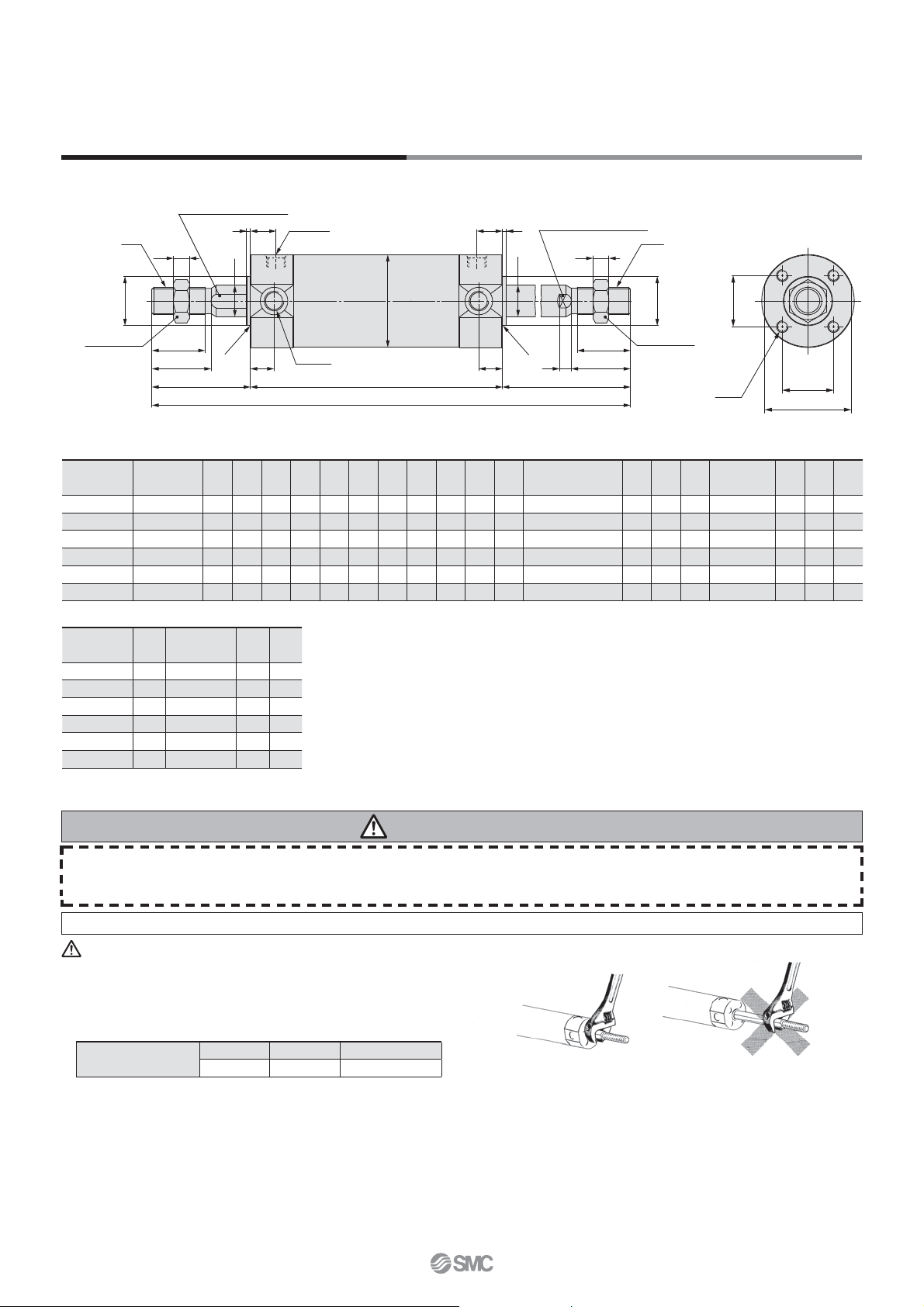
Series CG1KW
Basic with Rubber Bumper: CG1KWBN
Width across flats KB
P
MM
0
−0.05
øE
Width across
flats
B
1
F
H1 H1
øD
AL
R0.4
A
HH
2 x Rc
4 x TC
øI
S + Stroke
+ 2 Stroke
ZZ
Width across flats KA
F
GAGA
MM
øD
0
−0.05
R0.4
AL
TATA
K
A
+ Stroke
øE
Width across
flats
B
C
1
8 x J
C
NA
[mm]
Bore size Stroke range
20
25
32
40
50
63
Bore size
20
25
32
40
50
63
Up to 1500 18 15.5 13 14 8 9.2 12 2 12 5 26 M4 x 0.7 depth 7 5 6 8 M8 x 1.25 24 1/8 77
Up to 1500 22 19.5 17 16.5 10 11 14 2 12 6 31 M5 x 0.8 depth 7.5 5.5 8 10
Up to 1500 22 19.5 17 20 12 12 18 2 12 6 38 M5 x 0.8 depth 8 5.5 10 10
Up to 1500 30 27 19 26 16 16 25 2 13 8 47 M6 x 1 depth 12 6 14 14 M14 x 1.5 44 1/8 87
Up to 1500 35 32 27 32 20 20 30 2 14 11 58
Up to 1500 35 32 27 38 20 20 32 2 14 11 72
TA TC H ZZ
11 M5 x 0.8 35 147
11 M6 x 0.75 40 157
11 M8 x 1.0 40 159
12 M10 x 1.25 50 187
13 M12 x 1.25 58 218
13 M14 x 1.5 58 218
AALB1 C D DK E F GA H1 IJKKAKBMMNAPS
[mm]
M10 x 1.25
M10 x 1.25 35.5
M8 x 1.25 depth 16
M10 x 1.5 depth 16
Note 1) Dimensions are the same as those for the CG1W standard. Refer to pages 9 to 14.
Note 2) When the stroke exceeds the standard stroke, it is beyond the guarantee.
7 18 18 M18 x 1.5 55 1/4 102
7 18 18 M18 x 1.5 69 1/4 102
29 1/8 77
1/8 79
Precautions
Be sure to read before handling. Refer to back cover for Safety Instructions. For Actuator and Auto Switch
Precautions, refer to “Handling Precaution for SMC Products” and the Operation Manual on SMC website,
http://www.smcworld.com
Caution on Handling/Disassembly
Caution
1. Avoid using the air cylinder in such a way that
rotational torque would be applied to the piston rod.
¡
If rotational torque is applied, the non-rotating guide will become deformed,
thus affecting the non-rotating accuracy. Refer to the table below for the
approximate values of the allowable range of rotational torque.
Allowable rotational torque
N·m or less
¡
To screw a bracket or a nut onto the piston rod, make sure to retract the
piston rod entirely, and place a wrench over the fl at portion of the rod
ø20 ø25, ø32 ø40, ø50, ø63
0.2 0.25 0.44
that protrudes. Tighten it by giving consideration to prevent the tightening
torque from being applied to the non-rotating guide.
2. When replacing rod seals, please contact SMC.
Air leakage may be happened, depending on the position in which a
rod seal is fi tted. Thus, please contact SMC when replacing them.
37

Air Cylinder: Direct Mount Type
Double Acting
Series CG1R
ø20, ø25, ø32, ø40, ø50, ø63
CG1CG1WCG1CG1KCG1KWCG1R
CG1R
With auto switch
With auto switch
(Built-in magnet)
Built-in Magnet Cylinder Model
If a built-in magnet cylinder without an
auto switch is required, there is no need
to enter the symbol for the auto switch.
(Example) CDG1RA32-100Z
CDG1R
Rubber bumper
N
A
Air cushion
Refer to “Standard Strokes” on page 39.
How to Order
25
25
NZ
Type
Bore size
20 mm
20
25 mm
25
32 mm
32
40 mm
40
50 mm
50
63 mm
63
Cylinder stroke [mm]
100
100
ZN
M9BW
Rod end thread
F
Male rod end
Female rod end
—
Number of auto switches
2 pcs.
—
1 pc.
S
“n” pcs.
n
Auto switch
Without auto switch
—
∗ For applicable auto switches, refer to
the table below.
Made to Order
For details, refer to page 39.
Double Acting, Single RodDouble Acting, Double Rod
StandardNon-rotating RodDirect Mount
Single Acting, Spring Return/Extend
Double Acting, Single RodDouble Acting, Double RodDouble Acting, Single Rod
Applicable Auto Switches/Refer to the Auto Switch Guide for further information on auto switches.
Load voltage Auto switch model Lead wire length [m]
Type
Special function
———
Diagnostic indication
(2-colour indication)
Water resistant
(2-colour indication)
Solid state auto switch
Diagnostic output (2-colour indication)
———
Reed auto switch
Diagnostic indication (2-colour indication)
∗∗ Water resistant type auto switches can be mounted on the above models, but in such case SMC cannot guarantee water resistance.
Please consult with SMC regarding water resistant types with the above model numbers.
∗ Lead wire length symbols: 0.5 m·················· — (Example) M9NW
1 m·················· M
3 m··················
5 m·················· Z (Example) M9NWZ
None
∗ Since there are other applicable auto switches than listed, refer to page 47 for details.
∗ For details about auto switches with pre-wired connector, refer to the Auto Switch Guide.
∗ The D-A9쏔쏔/M9쏔쏔쏔 auto switches are shipped together, (but not assembled). (However, only the auto switch mounting brackets are assembled before shipment.)
Electrical
entry
Grommet
Connector —
Grommet
Grommet
Connector
Grommet
··············· N (Example) H7CN
Wiring
(Output)
Indicator light
3-wire (NPN)
3-wire (PNP)
2-wire 12 V
3-wire (NPN)
Yes
3-wire (PNP)
2-wire 12 V
3-wire (NPN)
3-wire (PNP)
2-wire 12 V
4-wire (NPN)
3-wire
(Equiv. to NPN)
Yes
None
Yes
None
2-wire 24 V
Yes
None
Yes
(Example) M9NWM
L
(Example) M9NWL
DC AC
5 V, 12 V
5 V, 12 V
24 V
5 V, 12 V
5 V, 12 V
—5 V —
12 V
—— —
—
100 V
100 V or less
100 V, 200 V
200 V or less
——
24 V or less —
∗ Solid state auto switches marked with “쑗” are produced upon receipt of order.
Applicable bore size
ø20 to ø63
Perpendicular
M9NV M9N
M9PV M9P
M9BV M9B
M9NWV M9NW
M9PWV M9PW
M9BWV M9BW
M9NAV∗∗M9NA
M9PAV∗∗M9PA
M9BAV∗∗M9BA
—
A96V A96
A93V A93
A90V A90
—
—
In-line
H7C
H7NF
B54
B64
C73C
C80C
B59W
0.5
(—)1[m]3(L)5(Z)
∗∗
∗∗
∗∗
None
[N]
—
—
—
—— —
—
—
—— —
—
—
—— —
—
—
—
—— — —
Pre-wired
connector
—
—
—
—
—
—
—
—
—
—
—— —
——
—
—
—
Applicable load
IC
circuit
—
IC
circuit
—
IC
circuit
—
IC circuit
IC
circuit
IC circuit
—
IC circuit
Relay,
PLC
—
Relay,
PLC
Auto SwitchMade to Order
38
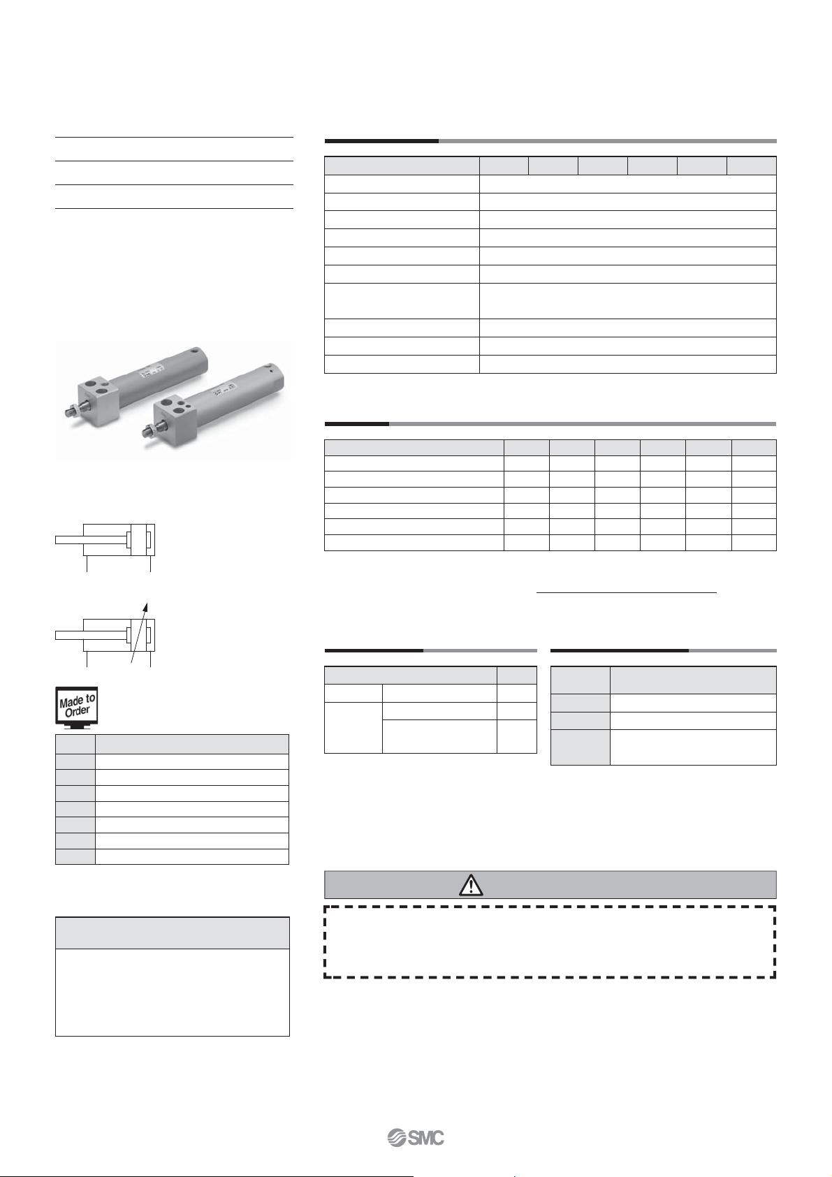
Series CG1R
The CG1R direct mount cylinder
can be installed directly through
the use of a square rod cover.
Space-saving is granted.
Because it is a directly mounted style without
using brackets, its overall length is shorter,
and its installation pitch can be made smaller.
Thus, the space that is required for
installation has been dramatically reduced.
Symbol
Rubber bumper
Air cushion
Specifi cations
Bore size [mm]
Action Double acting, Single rod
Lubricant Not required (Non-lube)
Fluid Air
Proof pressure 1.5 MPa
Maximum operating pressure
Minimum operating pressure
Ambient and fl uid
temperature
Piston speed 50 to 1000 mm/s
Stroke length tolerance
Cushion Rubber bumper, Air cushion
20 25 32 40 50 63
1.0 MPa
0.05 MPa
Without auto switch: –10°C to 70°C
With auto switch : –10°C to 60°C
Up to 300 st
+1.4
0
(No freezing)
mm
Weights
Bore size [mm]
Basic weight 0.14 0.23 0.35 0.57 1.04 1.49
Single knuckle joint 0.05 0.09 0.09 0.10 0.22 0.22
Double knuckle joint (with pin) 0.05 0.09 0.09 0.13 0.26 0.26
Additional weight per 50 mm of stroke
Additional weight with air cushion 0.01 0.01 0.02 0.02 0.03 0.03
Weight reduction for female rod end −0.01 −0.02 −0.02 −0.05 −0.10 −0.10
Calculation (Example) CG1RN32-100Z
(ø32, 100 stroke)
20 25 32 40 50 63
0.05 0.07 0.09 0.15 0.22 0.26
Basic weight
¡
Basic weight
¡
Air cylinder stroke
¡
0.35 + 0.09 x 100/50 = 0.53 kg
·············· 0.35
·············· 0.09/50 stroke
····· 100 stroke
[kg]
Made to Order
(For details, refer to pages 49 to 65.)
Symbol Specifi cations
Made of stainless steel
-XC6
Adjustable stroke cylinder/Adjustable extension type
-XC8
Adjustable stroke cylinder/Adjustable retraction type
-XC9
Auto switch rail mounting
-XC13
Head cover axial port
-XC20
Fluororubber seal
-XC22
Grease for food processing equipment
-XC85
∗
Only compatible with cylinders with rubber bumper.
∗∗ Cylinders with rubber bumper have no bumper.
Refer to pages 42 to 47 for cylinders with
auto switches.
· Auto switch proper mounting position
(detection at stroke end) and its mounting
height
· Minimum stroke for auto switch mounting
· Operating range
· Auto switch mounting brackets/Part no.
∗
∗
∗
Accessories Standard Strokes
Mounting Basic
Standard Rod end nut
Single knuckle joint
Option
∗
∗
∗ A double knuckle joint pin and retaining
rings are shipped together.
Double knuckle joint∗
(with pin)
Bore size
[mm]
20
25, 32
40, 50, 63
Note 1) Intermediate strokes not listed above are
produced upon receipt of order.
Manufacture of intermediate strokes at 1
mm intervals is possible. (Spacers are
not used.)
∗
For applicable long strokes, please contact SMC.
Standard stroke [mm]
25, 50, 75, 100, 125, 150
25, 50, 75, 100, 125, 150, 200
25, 50, 75, 100, 125, 150,
200, 250, 300
∗
Precautions
Be sure to read before handling.
Refer to back cover for Safety Instructions. For Actuator and Auto
Switch Precautions, refer to “Handling Precaution for SMC Products”
and the Operation Manual on SMC website, http://www.smcworld.com
When the cylinder is used as mounted with a single side fixed or free, a
bending moment will be applied to the cylinder due to the vibration
generated at the stroke end, and the cylinder may be damaged. In such a
case, mount a bracket to reduce the vibration of the cylinder or use the
cylinder at a piston speed low enough to prevent the cylinder from vibrating
at the stroke end.
Also, use a support bracket when the cylinder body moves or when the
long stroke cylinder is fi xed horizontally on one side.
39

Construction
Air Cylinder: Direct Mount Type
Double Acting
Series CG1R
With rubber bumper
ort qy we!8 iu!9
!7
With air cushion
qr!2 !1!9 !5 w!0 ei!6!4
Component Parts
No. Description Material Note
1 Rod cover Aluminium alloy Hard Anodised
2 Tube cover Aluminium alloy Hard Anodised
3 Piston Aluminium alloy
4 Piston rod
5 Bushing Bearing alloy
6 Bumper Resin
7 Bumper Resin
8 Wear ring Resin
9 Rod end nut Carbon steel Zinc chromated
10 Cushion ring A Aluminium alloy
Stainless steel
Carbon steel∗Hard chrome plating
For ø20 or ø25 with built-in magnet
ø32 or larger is
common.
CG1CG1WCG1CG1KCG1KWCG1R
Double Acting, Single RodDouble Acting, Double Rod
StandardNon-rotating RodDirect Mount
@0 !3o!7 t!8
Single Acting, Spring Return/Extend
Double Acting, Single RodDouble Acting, Double RodDouble Acting, Single Rod
No. Description Material Note
11 Cushion ring B Aluminium alloy
12 Seal retainer Rolled steel Zinc chromated
Cushion
13
valve
∗
14 Steel ball Carbon steel
15 Cushion seal A Urethane
16 Cushion seal B Urethane
17 Rod seal NBR
18 Piston seal NBR
19 Tube gasket NBR
20 Valve seal NBR
Note)
For cylinders with auto switches, the magnet is installed in the piston.
∗
The material for ø20, ø25 cylinders with auto switches is made of stainless
steel.
ø40 or smaller
ø50 or larger
Carbon steel
Steel wire Zinc chromated
Electroless nickel plating
ø32 or larger is
common.
Replacement parts/Seal kit are the same as standard type, double
acting, single rod. Refer to page 6.
Note) Refer to the Specifi c Product Precautions on page 5 for Disassembly/
Replacement.
40
Auto SwitchMade to Order

Series CG1R
Basic with Bottom Mounting
With rubber bumper
With air cushion
°
10
Wθ
°
NA
Width across
flats
KA
MM
Width across
flats
B
1
Width across
flats
KA
MM
Width across
flats
B
1
H1
AL Y
A
K
H1
AL Y
A
K
X
GA
2 x RcP
øD
øI
GB
R0.4
0
−0.05
øE
L
2 x øLD
LH
LX
N
L
S + StrokeH
F
ZZ + Stroke
WA
GA
X
øD
2 x P
Cushion valve,
Width across flats
øI
WH
WB
GB
R0.4
0
−0.05
øE
2 x øLD
WC
L
LH
LX
N
L
ZZ
S + StrokeH
+ Stroke
F
Effective depth A1
20
25
32
40
50
63
Stroke
AALB1 DEFGAGBHH1 I K KA L LD LH LX MM N P S X Y ZZ
range
Up to 150
18 15.5 13 8 12 2 20 10 27 5 26 5 6 30.4
Up to 200
22 19.5 17 10 14 2 22 10 32 6 31 5.5 8 36.4
Up to 200
22 19.5 17 12 18 2 26 10 32 6 38 5.5 10 42.4
Up to 300
30 27 19 16 25 2 30 10 39 8 47 6 14 52.4
Up to 300
35 32 27 20 30 2 33 12 45 11 58 7 18 64.5
Up to 300
35 32 27 20 32 2 39 12 45 11 72 7 18 76.6
Bore size
With Air Cushion
Bore size
20
25
32
40
50
63
Stroke
range
Up to 150 M5 x 0.8 22 15 5.5 2 25° 1.5
Up to 200 M5 x 0.8 24 14.5 7 2 25° 1.5
Up to 200 Rc1/8 28 14 11.5 — 25° 1.5
Up to 300 Rc1/8 32 15 15 — 20° 1.5
Up to 300 Rc1/4 36 16 17.5 — 20° 3
Up to 300 Rc1/4 42 17 20.5 — 20° 3
41
MM
Female rod end
H
[mm]
P WAWBWCWD Wθ WH
ZZ
+ Stroke
ø5.5, ø9.5 depth of counterbore 6
ø6.6, ø11 depth of counterbore 7
ø11, ø17.5 depth of counterbore 12
ø14, ø20 depth of counterbore 14
ø18, ø26 depth of counterbore 18
Female Rod End
Bore size
20
25
32
40
50
63
port location
15 18
18 22
ø9, ø14 depth of counterbore 9
21 24
26 32
32 41
38 46
M8 x 1.25
M10 x 1.25
M10 x 1.25
M14 x 1.5
M18 x 1.5
M18 x 1.5
27 1/8 75 38 11 104
29 1/8 77 44 12 111
33 1/8 83 45 13 117
37 1/8 94 55 16 135
44 1/4 108 62 17 155
50 1/4 114 64 19 161
A1 HMMZZ
8 13 M4 x 0.7 90
8 14 M5 x 0.8 93
12 14 M6 x 1 99
13 15 M8 x 1.25 111
18 16 M10 x 1.5 126
18 16 M10 x 1.5 132
WD
ø20, ø25
[mm]
[mm]
Series CG1
Auto Switch Mounting
Auto Switch Proper Mounting Position (Detection at stroke end) and Its Mounting Height
Solid state auto switch
D-M9쏔
ø20
/M9쏔W, D-M9쏔A
to ø63
≈Hs
Reed auto switch
D-A9쏔
to ø63
ø20
≈Hs
CG1CG1WCG1CG1KCG1KWCG1R
Double Acting, Single RodDouble Acting, Double Rod
A 22
(24)
A and B are the dimensions from the end of the
head cover/rod cover to the end of the auto switch.
D-M9쏔V
ø20
/M9쏔WV, D-M9쏔AV
to ø63
A 20
(22)
A and B are the dimensions from the end of the
head cover/rod cover to the end of the auto switch.
D-G5/K5/G5쏔W/G5BA
D-K59W, D-G59F, D-G5NT
ø20
to ø100
B
( ): Dimension of the D-M9쏔A
≈Hs
B
( ): Dimension of the D-M9쏔AV
≈Hs
BA
16
16
24.5
D-A9쏔V
ø20
to ø63
D-C7/C8
to ø63
ø20
A 24.5
(22)
A and B are the dimensions from the end of the
head cover/rod cover to the end of the auto switch.
22 B
A
A and B are the dimensions from the end of the
head cover/rod cover to the end of the auto switch.
B
( ): Dimension of the D-A96
, D-C73C/C80C
AB
16
StandardNon-rotating RodDirect Mount
≈Hs
16
Single Acting, Spring Return/Extend
Double Acting, Single RodDouble Acting, Double RodDouble Acting, Single Rod
≈Hs
16
D-H7쏔/H7쏔W
D-H7NF/H7BA/D-H7C
D-B5/B6/B59W
to ø100
ø20
ø20 to ø63
≈Hs
16
AB
Auto Switch Mounting Height [mm]
Auto switch
Bore size
20
25
32
40
50
63
80
100
model
D-H7
D-M9쏔V
D-M9쏔WV
D-M9쏔AV
D-A9쏔V
Hs Hs Hs Hs
25.5 24.5 27 27.5
28 27 29.5 30
31.5 30.5 33 33.5
36 35 37.5 38
41.5 40.5 43 43.5
48.5 47.5 50 50.5
———59
— — — 69.5
D-M9
쏔
D-M9쏔W
D-M9쏔A
D-A9
쏔
쏔
D-H7쏔W
D-H7NF
D-H7BA
D-C7/C8
D-C73C
D-C80C
D-G5/K5
D-G5쏔W
D-K59W
D-B5/B6
D-B59W
D-G5NT
D-G59F
D-H7C
D-G5BA
≈Hs
24.5
BA
Auto SwitchMade to Order
42

Series CG1
Auto Switch Proper Mounting Position (Detection at stroke end)
Auto Switch Proper Mounting Position/Except Single Acting and Direct Mount Type (CG1R) [mm]
D-M9
Auto switch
model
Bore size
20
25
32
40
50
63
80
100
Note 1) Figures in parentheses are for the long stroke type.
Note 2) Adjust the auto switch after confi rming the operating condition in the actual setting.
쏔
D-M9쏔V
D-M9쏔W
D-M9쏔WV
D-M9쏔A
D-M9쏔AV
D-A9
쏔
D-A9쏔V
D-H7쏔W
D-H7NF
D-H7BA
D-H7
쏔
D-H7C
D-C7
쏔
D-C80
D-C73C
D-C80C
D-G5쏔/K59
D-G5쏔W/K59W
D-G59F
D-G5NT
D-G5BA
D-B5
D-B64
쏔
D-B59W
ABABABABABABAB
33
32.5
34
39
46
44.5
— — — — — — — — 49.5
— — — — — — — — 48.5
24
(32)
24.5
(32.5)
25
(33)
27
(36)
32
(44)
33.5
(45.5)
29
28.5
30
35
42
40.5
20
(28)
20.5
(28.5)
21
(29)
23
(32)
28
(40)
29.5
(41.5)
28.5
28
29.5
34.5
41.5
40
19.5
(27.5)
20
(28)
20.5
(28.5)
22.5
(31.5)
27.5
(39.5)
29
(41)
29.5
29
30.5
35.5
42.5
41
20.5
(28.5)
21
(29)
21.5
(29.5)
23.5
(32.5)
28.5
(40.5)
30
(42)
25
24.5
26
31
38
36.5
16
(24)
16.5
(24.5)
17
(25)
19
(28)
24
(36)
25.5
(37.5)
30.5
(44.5)
31.5
(45.5)
23.5
23
24.5
29.5
36.5
35
48
47
14.5
(22.5)
15
(23)
15.5
(23.5)
17.5
(26.5)
22.5
(34.5)
24
(36)
29
(43)
30
(44)
26.5
26
27.5
32.5
39.5
38
51
50
17.5
(23.5)
18
(26)
18.5
(26.5)
20.5
(29.5)
25.5
(37.5)
27
(39)
32
(46)
33
(47)
Auto Switch Proper Mounting Position (Detection at stroke end)
Single Acting, Spring Return Type (S)/Spring Extend Type (T)
Auto Switch Proper Mounting Position/Single Acting, Spring Return Type (S) [mm]
Auto switch model Bore size
D-M9쏔(V)
D-M9쏔W(V)
D-M9쏔A(V)
D-A9쏔(V)
D-H7
쏔
D-H7쏔W
D-H7C
D-H7BA
D-H7NF
D-C7
쏔
D-C80
D-C73C
D-C80C
D-G5NT
D-G59F
D-B5
쏔
D-B64
D-B59W
Note) Adjust the auto switch after confi rming the operating condition in the actual setting.
20 58 83 108 — 24
25 57.5 82.5 107.5 132.5 24.5
32 59 84 109 134 25
40 64 89 114 139 27
20 54 79 104 — 20
25 53.5 78.5 103.5 128.5 20.5
32 55 80 105 130 21
40 60 85 110 135 23
20 53.5 78.5 103.5 — 19.5
25 53 78 103 128 20
32 54.5 79.5 109.5 129.5 20.5
40 59.5 84.5 109.5 134.5 22.5
20 54.5 79.5 104.5 — 20.5
25 54 79 104 129 21
32 55.5 80.5 105.5 130.5 21.5
40 60.5 85.5 110.5 135.5 23.5
20 50 75 100 — 16
25 49.5 74.5 99.5 124.5 16.5
32 51 76 101 126 17
40 56 81 106 131 19
20 48.5 73.5 98.5 — 14.5
25 48 73 98 123 15
32 49.5 74.5 99.5 124.5 15.5
40 54.5 79.5 104.5 129.5 17.5
20 51.5 76.5 101.5 — 17.5
25 51 76 101 126 18
32 52.5 77.5 102.5 127.5 18.5
40 57.5 82.5 107.5 132.5 20.5
Up to 50 st 51 to 100 st 101 to 125 st 126 to 200 st
A dimensions
B
43

Auto Switch Mounting
Series CG1
Auto Switch Proper Mounting Position/Single Acting, Spring Extend Type (T) [mm]
Auto switch model Bore size
D-M9쏔(V)
D-M9쏔W(V)
D-M9쏔A(V)
D-A9쏔(V)
D-H7
쏔
D-H7쏔W
D-H7C
D-H7BA
D-H7NF
D-C7
쏔
D-C80
D-C73C
D-C80C
D-G5NT
D-G59F
D-B5
쏔
D-B64
D-B59W
Note) Adjust the auto switch after confi rming the operating condition in the actual setting.
20 33 49 74 99 —
25 32.5 49.5 74.5 99.5 124.5
32 34 50 75 100 125
40 39 52 77 102 127
20 29 45 70 95 —
25 28.5 45.5 70.5 95.5 120.5
32 30 46 71 96 121
40 35 48 73 98 123
20 28.5 44.5 69.5 94.5 —
25 29 45 70 95 120
32 29.5 45.5 70.5 95.5 120.5
40 34.5 47.5 72.5 97.5 122.5
20 29.5 45.5 70.5 95.5 —
25 29 46 71 96 121
32 30.5 46.5 71.5 96.5 121.5
40 35.5 48.5 73.5 98.5 123.5
20 25 41 66 91 —
25 24.5 41.5 66.5 91.5 116.5
32 26 42 67 92 117
40 31 44 69 94 119
20 23.5 39.5 64.5 89.5 —
25 23 40 65 90 115
32 24.5 40.5 65.5 90.5 115.5
40 29.5 42.5 67.5 92.5 117.5
20 26.5 42.5 67.5 92.5 —
25 26 43 68 93 118
32 27.5 43.5 68.5 93.5 118.5
40 32.5 45.5 70.5 95.5 120.5
A
Up to 50 st 51 to 100 st 101 to 125 st 126 to 200 st
B dimensions
CG1CG1WCG1CG1KCG1KWCG1R
Double Acting, Single RodDouble Acting, Double Rod
StandardNon-rotating RodDirect Mount
Single Acting, Spring Return/Extend
Auto Switch Proper Mounting Position (Detection at stroke end)
Auto Switch Proper Mounting Position/Direct Mount Type (CG1R) [mm]
D-M9
Auto switch
model
Bore size
20
25
32
40
50
63
Note) Adjust the auto switch after confi rming the operating condition in the actual setting.
쏔
D-M9쏔V
D-M9쏔W
D-M9쏔WV
D-M9쏔A
D-M9쏔AV
D-A9
쏔
D-A9쏔V
D-H7쏔W
D-H7NF
D-H7BA
D-H7
쏔
D-H7C
D-C7
쏔
D-C80
D-C73C
D-C80C
D-G59F
D-G5NT
D-B5
D-B64
쏔
D-B59W
ABABABABABABAB
12 24 8 20 7.5 19.5 8.5 20.5 4 16 2.5 14.5 5.5 17.5
11.5 24.5 7.5 20.5 7 20 8 21 3.5 16.5 2 15 5 18
13 25 9 21 8.5 20.5 9.5 21.5 5 17 3.5 15.5 6.5 18.5
18 27 14 23 13.5 22.5 14.5 23.5 10 19 8.5 17.5 11.5 20.5
20 32 16 28 17.5 27.5 16.5 28.5 14 24 10.5 22.5 13.5 25.5
18.5 33.5 14.5 29.5 16 29 15 30 12.5 25.5 8 24 12 27
Double Acting, Single RodDouble Acting, Double RodDouble Acting, Single Rod
Auto SwitchMade to Order
44

Series CG1
Minimum Stroke for Auto Switch Mounting
Auto switch model
D-M9쏔
D-M9쏔W
D-M9쏔A
D-A9쏔
D-M9쏔V
D-A9쏔V
D-M9쏔WV
D-M9쏔AV
D-C7쏔
D-C80
D-H7쏔
D-H7쏔W
D-H7BA
D-H7NF
D-C73C
D-C80C
D-H7C
With 1 pc.
515
10 15
Different surfaces Same surface Different surfaces Same surface
Note 1)
Note 1)
10 25 40
51530
52035
51525
10 20 35
51550
10 15 60
51565
n: Number of auto switches [mm]
Number of auto switches
With 2 pcs. With n pcs.
(n – 2)
40
40
Note 1)
Note 1)
Note 1)
Note 1)
20 + 35
(n = 2, 4, 6···)
(n – 2)
20 + 35
(n = 2, 4, 6···)
(n – 2)
25 + 35
(n = 2, 4, 6···)
(n – 2)
15 + 35
(n = 2, 4, 6···)
(n – 2)
20 + 35
(n = 2, 4, 6···)
(n – 2)
15 + 35
(n = 2, 4, 6···)
(n – 2)
20 + 35
(n = 2, 4, 6···)
(n – 2)
15 + 45
(n = 2, 4, 6···)
(n – 2)
15 + 45
(n = 2, 4, 6···)
(n – 2)
15 + 50
(n = 2, 4, 6···)
2
Note 3)
2
Note 3)
2
Note 3)
2
Note 3)
2
Note 3)
2
Note 3)
2
Note 3)
2
Note 3)
2
Note 3)
2
Note 3)
55 + 35 (n – 2)
(n = 2, 3, 4, 5···)
55 + 35 (n – 2)
(n = 2, 3, 4, 5···)
60 + 35 (n – 2)
(n = 2, 3, 4, 5···)
50 + 35 (n – 2)
(n = 2, 3, 4, 5···)
35 + 35 (n – 2)
(n = 2, 3, 4, 5···)
25 + 35 (n – 2)
(n = 2, 3, 4, 5···)
35 + 35 (n – 2)
(n = 2, 3, 4, 5···)
50 + 45 (n – 2)
(n = 2, 3, 4, 5···)
60 + 45 (n – 2)
(n = 2, 3, 4, 5···)
65 + 50 (n – 2)
(n = 2, 3, 4, 5···)
D-B5쏔
D-B64
D-G5쏔
51575
D-K59쏔
D-B59W
Note 1) Auto switch mounting
Auto switch model
10 20 75
Note 3) When “n” is an odd number, an even number that is one larger than this odd number is used for the calculation.
With 2 auto switches
Different surfaces Same surface
A
3.5
15
B
The auto switch is mounted by slightly displacing it in a
D-M9쏔
D-M9쏔W
D-M9쏔A
D-A9쏔
Correct auto switch mounting position is 3.5 mm from the back
face of the switch holder.
Less than 20 stroke
Less than 20 stroke
Note 2)
Note 2)
— Less than 50 stroke
direction (cylinder tube circumferential exterior) so that the
auto switch and lead wire do not interfere with each other.
Note 2) Minimum stroke for auto switch mounting in styles other than those mentioned in Note 1.
(n – 2)
15 + 50
(n = 2, 4, 6···)
20 + 50
(n = 2, 4, 6···)
2
Note 3)
(n – 2)
2
Note 3)
Less than 55 stroke
Less than 60 stroke
75 + 55 (n – 2)
(n = 2, 3, 4, 5···)
75 + 55 (n – 2)
(n = 2, 3, 4, 5···)
Note 2)
Note 2)
Note 2)
45

Auto Switch Mounting Brackets/Part No.
Auto Switch Mounting
Series CG1
Auto switch model
D-M9쏔(V)
D-M9쏔W(V)
D-A9쏔(V)
D-M9쏔A(V)
Note 2)
Bore size [mm]
20 25 32 40 50 63 80 100
BMA3-020
(A set of a, b, c, d)
BMA3-020S
(A set of b, c, d, e)
BMA3-025
(A set of a, b, c, d)
BMA3-025S
(A set of b, c, d, e)
Switch bracket (Resin)
a
Transparent (nylon)
e
White (PBT)
c
Auto switch mounting band
∗ Band (c) is mounted so that the projected part is
BMA3-032
(A set of a, b, c, d)
BMA3-032S
(A set of b, c, d, e)
b
Switch holder
on the internal side (contact side with the tube).
BMA3-040
(A set of a, b, c, d)
BMA3-040S
(A set of b, c, d, e)
Note 1)
BMA3-050
(A set of a, b, c, d)
BMA3-050S
(A set of b, c, d, e)
Auto switch
Auto switch
mounting screw
BMA3-063
(A set of a, b, c, d)
BMA3-063S
(A set of b, c, d, e)
d
——
——
CG1CG1WCG1CG1KCG1KWCG1R
Double Acting, Single RodDouble Acting, Double Rod
StandardNon-rotating RodDirect Mount
Single Acting, Spring Return/Extend
D-C7쏔/C80
D-C73C/C80C
D-H7쏔
D-H7쏔W
BMA2-020A
(A set of band and screw)
BMA2-025A
(A set of band and screw)
BMA2-032A
(A set of band and screw)
BMA2-040A
(A set of band and screw)
BMA2-050A
(A set of band and screw)
BMA2-063A
(A set of band and screw)
——
D-H7NF
D-H7BA
BMA2-020AS
(A set of band and screw)
BMA2-025AS
(A set of band and screw)
BMA2-032AS
(A set of band and screw)
BMA2-040AS
(A set of band and screw)
BMA2-050AS
(A set of band and screw)
BMA2-063AS
(A set of band and screw)
——
D-B5쏔/B64
D-B59W
D-G5쏔/K59
D-G5쏔W/K59W
D-G5BA/G59F
BA-01
(A set of band and screw)
BA-02
(A set of band and screw)
BA-32
(A set of band and screw)
BA-04
(A set of band and screw)
BA-05
(A set of band and screw)
BA-06
(A set of band and screw)
BA-08
(A set of band and screw)
BA-10
(A set of band and screw)
D-G5NT
D-G5NB
Note 1) Since the switch bracket (made from nylon) are affected in an environment where alcohol, chloroform, methylamines, hydrochloric acid or sulfuric
acid is splashed over, so it cannot be used.
Please contact SMC regarding other chemicals.
Note 2) Avoid the indicator LED for mounting the switch bracket. As the indicator LED is projected from the switch unit, indicator LED may be damaged if
the switch bracket is fi xed on the indicator LED.
Band Mounting Brackets Set Part No.
Set part no. Contents
BM2-쏔쏔쏔A(S)
∗ S: Stainless steel screw
BJ4-1
BJ5-1
[Stainless Steel Mounting Screw]
The following stainless steel mounting screw kit is available. Use it in accordance with the operating environment.
(Since the auto switch mounting bracket is not included, order it separately.)
BBA3: D-B5/B6/G5/K5 types
Note 3) Refer to the WAuto Switch Guide for details on the BBA3.
When the D-G5BA type auto switch is shipped independently, the BBA3 is attached.
· Auto switch mounting band (c)
· Auto switch mounting screw (d)
· Switch bracket (White/PBT) (e)
· Switch holder (b)
· Switch bracket (Transparent/Nylon) (a)
· Switch holder (b)
Double Acting, Single RodDouble Acting, Double RodDouble Acting, Single Rod
Auto SwitchMade to Order
46

Series CG1
Operating Range
[mm]
Auto switch model
20 25 32 40 50 63 80 100
D-M9쏔(V)
D-M9쏔W(V)
4.5 5.0 4.5 5.5 5.0 5.5 — —
D-M9쏔A(V)
D-A9쏔
D-C7/C80
D-C73C/C80C
D-B5쏔/B64
D-B59W
D-H7쏔/H7쏔W
D-H7NF/H7BA
D-H7C
D-G5쏔/G5쏔W/G59F
D-G5BA/K59/K59W
D-G5NT
D-G5NB
∗ Values which include hysteresis are for guideline purposes only, they are not a guarantee (assuming approximately ±30% dispersion) and may change
substantially depending on the ambient environment.
768889——
8 10 9 10 10 11 — —
8 10 9 10 10 11 11 11
13 13 14 14 14 17 16 18
4 4 4.5 5 6 6.5 — —
7 8.5 9 10 9.5 10.5 — —
4 4 4.5 5 6 6.5 6.5 7
4 4 4.5 5 6 6.5 6.5 7
35 40 40 45 45 45 45 50
Bore size
Cylinder Mounting Bracket, by Stroke/Auto Switch Mounting Surfaces
st: Stroke [mm]
Basic, Foot, Flange, Clevis Trunnion
Auto switch model
Auto switch mounting
surface
Auto switch type
D-M9쏔(V)
D-M9쏔W(V)
D-M9쏔A(V)
D-A9쏔
D-C7/C8
D-H7쏔/H7쏔W
D-H7BA/H7NF
D-C73C/C80C/H7C
D-B5/B6/G5/K5
D-G5쏔W/K59W/G5BA
D-G59F/G5NT
D-B59W
∗ Trunnion type is not available for ø80 and ø100.
Other than the applicable auto switches listed in “How to Order”, the following auto switches are mountable.
Refer to the Auto Switch Guide for the detailed specifi cations.
Type Model Electrical entry Features Applicable bore size [mm]
Solid state
Reed
∗ With pre-wired connector is also available for solid state auto switches. For details, refer to the Auto Switch Guide.
∗ Normally closed (NC = b contact) solid state auto switches (D-F9G/F9H) are also available. For details, refer to the Auto Switch Guide.
∗ Wide range detection type, solid state auto switch (D-G5NB) is also available. For details, refer to the Auto Switch Guide.
With 1 pc.
(Rod cover side)
Port surface Port surface Port surface
10 st or more 15 to 44 st 45 st or more 10 st or more 15 to 44 st 45 st or more
10 st or more 15 to 49 st 50 st or more 10 st or more 15 to 49 st 50 st or more
10 st or more 15 to 59 st 60 st or more 10 st or more 15 to 59 st 60 st or more
10 st or more 15 to 64 st 65 st or more 10 st or more 15 to 64 st 65 st or more
10 st or more 15 to 74 st 75 st or more 10 st or more 15 to 74 st 75 st or more
15 st or more 20 to 74 st 75 st or more 15 st or more 20 to 74 st 75 st or more
D-H7A1, H7A2, H7B
D-H7NW, H7PW, H7BW Diagnostic indication (2-colour indication)
D-H7BA Water resistant (2-colour indication)
D-G5NT With timer ø20 to ø100
D-C73, C76 —
D-C80 Without indicator light
D-B53 — ø20 to ø100
With 2 pcs.
(Different surfaces)
Grommet (In-line)
With 2 pcs.
(Same surface)
With 1 pc.
(Rod cover side)
—
With 2 pcs.
(Different surfaces)
With 2 pcs.
(Same surface)
ø20 to ø63
ø20 to ø63
47

Prior to Use
Auto Switch Connection and Example
Sink Input Specifi cations Source Input Specifi cations
3-wire, NPN
Auto switch
Brown
Black
Blue
Input
COM
(PLC internal circuit)
3-wire, PNP
Auto switch
Brown
Black
Blue
Input
COM
(PLC internal circuit)
CG1CG1WCG1CG1KCG1KWCG1R
Double Acting, Single RodDouble Acting, Double Rod
2-wire
Auto switch
Connect according to the applicable PLC input specifi cations, as the connection method will vary depending on the PLC input specifi cations.
Brown
Blue
Input
COM
(PLC internal circuit)
2-wire
Auto switch
Brown
Blue
COM
Input
(PLC internal circuit)
Example of AND (Series) and OR (Parallel) Connection
∗
When using solid state auto switches, ensure the application is set up so the signals for the fi rst 50 ms are invalid.
3-wire AND connection for NPN output
(Using relays)
Auto switch 1
Auto switch 2
Brown
Black
Blue
Brown
Black
Blue
Relay
Load
3-wire AND connection for PNP output
(Using relays)
Brown
Auto switch 1
Black
Blue
Relay
(Performed with auto switches only)
Brown
Load
Auto switch 1
Auto switch 2
(Performed with auto switches only)
Auto switch 1
Black
Blue
Brown
Black
Blue
Brown
Black
Blue
3-wire OR connection for NPN output
Brown
Auto switch 1
Auto switch 2
Black
Brown
Black
Load
Blue
Blue
3-wire OR connection for PNP output
Brown
Auto switch 1
Black
Blue
StandardNon-rotating RodDirect Mount
Single Acting, Spring Return/Extend
Double Acting, Single RodDouble Acting, Double RodDouble Acting, Single Rod
Brown
Auto switch 2
Auto switch 1
Auto switch 2
Load voltage at ON = Power supply voltage –
Example: Power supply is 24 VDC
Black
Blue
Brown
Load
Blue
Brown
Blue
Residual voltage x 2 pcs.
= 24 V − 4 V x 2 pcs.
= 16 V
Internal voltage drop in auto switch is 4 V.
When two auto switches are
connected in series, a load
may malfunction because
the load voltage will decline
when in the ON state.
The indicator lights will light
up when both of the auto
switches are in the ON state.
Auto switches with load
voltage less than 20 V
cannot be used.
Load
Brown
Load
Auto switch 2
Black
Blue
Auto switch 2
2-wire OR connection2-wire AND connection
Brown
Load
Auto switch 1
Blue
Brown
Auto switch 2
Blue
Load voltage at OFF = Leakage current x 2 pcs. x
Load impedance
= 1 mA x 2 pcs. x 3 kΩ
= 6 V
Example: Load impedance is 3 kΩ.
Leakage current from auto switch is 1 mA.
(Solid state) (Reed)
When two auto
switches are
connected in parallel,
malfunction may occur
because the load
voltage will increase
when in the OFF state.
Brown
Black
Load
Blue
Because there is no
current leakage, the load
voltage will not increase
when turned OFF.
However, depending on
the number of auto
switches in the ON state,
the indicator lights may
sometimes grow dim or
not light up, due to the
dispersion and reduction
of the current fl owing to
the auto switches.
Auto SwitchMade to Order
48

Series CG1
Simple Specials/Made to Order
Please contact SMC for detailed specifi cations, delivery and prices.
왎 Simple Specials
Symbol
-XA0 to 30
Change of rod end shape
왎 Made to Order
Symbol
-XB6
-XB7
-XB9
-XB13
-XC4
-XC6
-XC8
-XC9
Heat resistant cylinder (−10 to 150°C)
Cold resistant cylinder (−40 to 70°C)
Low speed cylinder (10 to 50 mm/s)
Low speed cylinder (5 to 50 mm/s)
With heavy duty scraper
Made of stainless steel
Adjustable stroke cylinder/Adjustable extension type
Adjustable stroke cylinder/Adjustable retraction type
The following special specifi cations can be ordered as a simplifi ed Made-to-Order.
There is a specifi cation sheet available on paper and CD-ROM. Please contact your SMC sales representatives if necessary.
CG1
Specifi cations
Single rod Double rod Single rod
Rubber Air Rubber Air Rubber
Specifi cations
Single rod Double rod Single rod
Rubber Air Rubber Air Rubber
(Standard type)
Double acting Single acting
CG1
(Standard type)
Double acting Single acting
-XC10
-XC11
-XC12
-XC13
-XC20
-XC22
-XC27
-XC29
-XC35
-XC37
-XC42
-XC85
-X446
Dual stroke cylinder/Double rod type
Dual stroke cylinder/Single rod type
Tandem cylinder
Auto switch rail mounting
Head cover axial port
Fluororubber seal
Double clevis and double knuckle joint pins made of stainless steel
Double knuckle joint with spring pin
With coil scraper
Larger throttle diameter of connecting port
Built-in shock absorber in head cover side
Grease for food processing equipment
PTFE grease
49

Simple Specials/Made to Order
Series CG1
CG1K
(Non-rotating rod type)
Double acting
Single rod Double rod
Rubber Air Rubber
CG1K
(Non-rotating rod type)
Double acting
Single rod Double rod
Rubber Air Rubber
CG1R
(Direct mount type)
Double acting
Single rod
Rubber Air
CG1R
(Direct mount type)
Double acting
Single rod
Rubber Air
Page
Page 51
Page
Page 53
Page 53
Page 53
Page 54
Page 54
Page 54
Page 55
Page 56
Page 57
CG1CG1WCG1CG1KCG1KWCG1R
Double Acting, Single RodDouble Acting, Double Rod
StandardNon-rotating RodDirect Mount
Single Acting, Spring Return/Extend
Page 58
Page 59
Page 59 to 61
Page 62
Page 62
Page 62
Page 63
Page 63
Page 63
Page 64
Page 65
Page 65
Double Acting, Single RodDouble Acting, Double RodDouble Acting, Single Rod
Auto SwitchMade to Order
50

Series CG1
Simple Specials
These changes are dealt with Simple Specials System.
1
Change of Rod End Shape
Applicable Series
Series Action
Standard type
CG1-Z
Non-rotating rod type
Direct mount type
CG1
CG1W
CG1K
CG1R
Double acting, Single rod
Double acting, Double rod
Double acting, Single rod
Double acting, Single rod
Precautions
Symbol for change of
rod end shape
XA0 to 30
XA0 to 30
XA0 to 30
XA0 to 30
Note
1. SMC will make appropriate arrangements if no dimension,
tolerance, or fi nish instructions are given in the diagram.
2. Standard dimensions marked with “∗” will be as follows to the rod
diameter (D). Enter any special dimension you desire.
Symbol:
Symbol:
Symbol:
MM
A0
A4
øRD
A8
øDC
A
H
30n
L
H
ALB
30n
H
Symbol:
Symbol:
Symbol:
A1
A5
øRD
W
A9
yC0.5 file chamfer
30n
H
B
30n
L
H
C
WA
W1T
H
D ≤ 6 씮 D − 1 mm 6 < D ≤ 25 씮 D − 2 mm D > 25 씮 D − 4 mm
3. In the case of double rod type and single acting retraction type, enter
the dimensions when the rod is retracted.
Symbol:
Symbol:
Symbol:
R sphere
A2
CøDAC0.5
A6
A10
W1
T
H
ALMM
30n
H
TP
H
Symbol:
Symbol:
Symbol:
R sphere
A3
30n
H
A7
ALMM
30n
H
A11
H
Symbol:
51
A12
C0.5
R sphere
øDA
TW1
H
Symbol:
A13
C
øDA
A
Symbol:
30n
H
C
MM
A14
AL
øDA
30n
A
H
Symbol:
A15
C
øDA
A
30n
H

Simple Specials
Series CG1
CG1CG1WCG1CG1KCG1KWCG1R
Double Acting, Single RodDouble Acting, Double Rod
StandardNon-rotating RodDirect Mount
Symbol:
Symbol:
Symbol:
A16
MM
A20
MM
A24
MM
øDA
AL
AC
H
ALK
H
AL
H
30n
30n
Symbol:
Symbol:
øDB
Symbol:
A17
MM
A21
MM
A25
MM
A
H
T
A
H
AL L K
H
30n
30n
øDA
Symbol:
Symbol:
MM
øDB
Symbol:
MM
A18
MM
A22
A26
A
ALHLB K
Symbol:
30n
A
H
Symbol:
30n
øDA
T
A
H
Symbol:
øDA
30n
A19
MM
A23
C
W
A27
øDA
A
øRD
L
B
A
MM
LA
30n
H
30n
H
30n
H
Single Acting, Spring Return/Extend
Double Acting, Single RodDouble Acting, Double RodDouble Acting, Single Rod
Symbol:
A28
MM
Symbol:
30n
øDA
A
L
H
MM
A29
T
LW
AL
30n
A
H
Symbol:
W
A30
MM
T
A
30n
H
Auto SwitchMade to Order
52

Series CG1
Made to Order
Please contact SMC for detailed dimensions, specifi cations and lead times.
1
Heat Resistant Cylinder (–10 to 150°C)
Air cylinder which changed the seal material and grease, so that it could be used even at higher temperature up to 150 from −10°C.
Symbol
-XB6
Applicable Series
Series
Description
CG1-Z
Note 1) Operate without lubrication from a pneumatic system lubricator.
Note 2) Please contact SMC for details on the maintenance intervals for this
Note 3)
Note 4) Piston speed is ranged from 50 to 500 mm/s.
Standard
type
cylinder, which differ from those of the standard cylinder.
In principle, it is impossible to make built-in magnet type and the one
with auto switch. But, as for the one with auto switch, and the heat
resistant cylinder with heat resistant auto switch, please contact SMC.
Model Action Note
CG1
Double acting,
Single rod
Except with auto switch.
Cylinders with rubber bumper
have no bumper.
How to Order
Standard model no.
Heat resistant cylinder
2
Cold Resistant Cylinder (−40 to 70°C)
Air cylinder which changed the seal material and grease, so that it could be used even at lower temperature down to −40°C.
XB6
Applicable Series
Series
Description
CG1-Z
Note 1) Operate without lubrication from a pneumatic system lubricator.
Note 2) Use dry air which is suitable for heatless air dryer etc. not to cause
Note 3) Please contact SMC for details on the maintenance intervals for this
Note 4) Mounting auto switch is impossible.
Note 5) Without a bumper.
Standard
type
the moisture to be frozen.
cylinder, which differ from those of the standard cylinder.
Piston speed is ranged from 50 to 500 mm/s.
Model Action Note
CG1
Double acting,
Single rod
Except with air cushion and auto
switch. Cylinders with rubber
bumper have no bumper.
How to Order
Standard model no.
XB7
Specifi cations
Ambient temperature range −10°C to 150°C
Seals materials Fluororubber
Grease Heat resistant grease
Specifi cations other than above
and external dimensions
Same as standard type
Warning
Precautions
Be aware that smoking cigarettes etc. after your hands have come into
contact with the grease used in this cylinder can create a gas that is
hazardous to humans.
Specifi cations
Ambient temperature range −40°C to 70°C
Seals material Low nitrile rubber
Grease Cold resistant grease
Auto switch Not mountable
Dimensions Same as standard type
Additional specifi cations Same as standard type
Warning
Precautions
Be aware that smoking cigarettes etc. after your hands have come into
contact with the grease used in this cylinder can create a gas that is
hazardous to humans.
Symbol
-XB7
Cold resistant cylinder
3
Low Speed Cylinder (10 to 50 mm/s)
Even if driving at lower speeds 10 to 50 mm/s, there would be no stick-slip phenomenon and it can run smoothly.
Applicable Series
Series
Description
CG1-Z
Note) Operate without lubrication from a pneumatic system lubricator.
Standard
type
Model Action Note
CG1
Double acting,
Single rod
Except with rod boot
and with air cushion
How to Order
Standard model no.
Low speed cylinder
XB9
Specifi cations
Piston speed 10 to 50 mm/s
Dimensions Same as standard type
Additional specifi cations Same as standard type
Warning
Precautions
Be aware that smoking cigarettes etc. after your hands have come into
contact with the grease used in this cylinder can create a gas that is
hazardous to humans.
53
Symbol
-XB9

4
Low Speed Cylinder (5 to 50 mm/s)
Made to Order
Series CG1
Symbol
-XB13
Even if driving at lower speeds 10 to 50 mm/s, there would be no stick-slip phenomenon and it can run smoothly.
Applicable Series
Series Description Model Action Note
CG1-Z
Note 1) Operate without lubrication from a pneumatic system lubricator.
Note 2) For speed adjustment, use speed controllers for controlling at
Standard type CG1
lower speeds. (Series AS-FM/AS-M)
Double acting,
Single rod
Except with rod boot
and with air cushion
Specifi cations
Piston speed 5 to 50 mm/s
Dimensions Same as standard type
Additional specifi cations Same as standard type
Warning
Precautions
How to Order
Standard model no.
Low speed cylinder
5
With Heavy Duty Scraper
It is suitable for using cylinders under the environment, where there are much dusts in a surrounding area by using a heavy duty scraper on the
wiper ring, or using cylinders under earth and sand exposed to the die-casted equipment, construction machinery, or industrial vehicles.
XB13
Applicable Series
Series Description Model Action Note
CG1-Z
Standard type CG1
Double acting,
Single rod
ø32 to ø63 only
How to Order
Standard model no.
With heavy duty scraper
(SCB scraper)
XC4
Be aware that smoking cigarettes etc. after your hands have come into
contact with the grease used in this cylinder can create a gas that is
hazardous to humans.
Symbol
-XC4
Specifi cations: Same as standard type
Caution
Do not replace heavy duty scrapers.
¡ Since heavy duty scrapers are press-fi t, they must be replaced together
with the scraper bracket.
CG1CG1WCG1CG1KCG1KWCG1R
Double Acting, Single RodDouble Acting, Double Rod
StandardNon-rotating RodDirect Mount
Single Acting, Spring Return/Extend
Double Acting, Single RodDouble Acting, Double RodDouble Acting, Single Rod
Dimensions
Bore size
32
40
50
63
∗ Other dimensions are the same as double
acting, single rod, standard type.
∗ On the axial foot and the rod fl ange types,
ZZ + Stroke
6
Made of Stainless Steel
Suitable for the cases it is likely to generate rust by being immersed in the water and corrosion.
Applicable Series
Series Description Model Action
Double acting, Single rod
Single acting (Spring return)
CG1-Z
Standard type CG1
Double rod type CG1W Double acting, Double rod
Direct mount type CG1R Double acting, Single rod
the installation bracket is wedged and
bolted between the cylinder and the
scraper at the time of shipment. On other
types, it is placed in the same package,
(but not assembled).
How to Order
Standard model no.
Specifi cations
Parts changed to stainless steel Piston rod, Rod end nut
Specifi cations other than above
and external dimensions
[mm]
E2 FA FB M I2 HZZ
17 8 3 5 38 48 121
21 8 3 6 48 58 138
26 9 3 8 59 66 158
26 9 3 10 72 66 158
Long Stroke
ZZ
129
147
170
170
Symbol
-XC6
XC6
Made of stainless steel
Same as standard type
Auto SwitchMade to Order
54

Series CG1
7
Adjustable Stroke Cylinder/Adjustable Extension Type
It adjusts the extending stroke by the stroke adjustable mechanism equipped in the head side.
Symbol
-XC8
Applicable Series
Series Description Model Action Note
CG1-Z
Standard type
Non-rotating rod type
Direct mount type
CG1
Double acting Except with air cushion
CG1K
Double acting Except with air cushion
CG1R
Double acting Except with air cushion
How to Order
StrokeBore sizeMounting style Type Stroke adjustment symbol
∗ Except clevis type
Dimensions
Series CG1
Symbol
(Dimensions other than below are the same as standard type.)
Stopper bracket
Adjustable stroke cylinder/adjustable extension type
Adjustable range
Width across flats MA
Stopper
Specifi cations
Stroke adjustment symbol A B
Stroke adjustment range [mm] 0 to 25 0 to 50
Additional specifi cations Same as standard type
XC8CG1 Z
Warning
Precautions
1.
When the cylinder is operating, if something gets caught between the
stopper bracket for adjusting the stroke and the cylinder body, it could
cause bodily injury or damage the peripheral equipment. Therefore, take
preventive measures as necessary, such as installing a protective cover.
2. To adjust the stroke, make sure to secure the wrench flats of the
stopper bracket by a wrench etc. before loosening the lock nut. If the
lock nut is loosened without securing the stopper bracket, be aware that
the area that joins the load to the piston rod or the area in which the
piston rod is joined with the load side and the stopper bracket side
could loosen fi rst. It may cause an accident or malfunction.
Width across flats B2
MM2
S
ZZ + 2 x Stroke + Adjustment (A: 25 mm, B: 50 mm)
Series CG1K/CG1R
+ Stroke
S
ZZ + 2 x Stroke + Adjustment (A: 25 mm, B: 50 mm)
+ Stroke
Stroke
MT
MH + Stroke + Adjustment
MH + Stroke + Adjustment
ML + Adjustment
Width across flats MA
øMI
ML + Adjustment
StrokeMT
øMI
MK
MK
H2
Bore
B2 H2 MA MH MI MK ML MM2 MT S ZZ
size
10 3.6 12 38 14 7 18 M6 x 1 9 77 150
20
13 5 17 41 20 9 18 M8 x 1.25 11 77 158
25
13 5 17 41 20 9 18 M8 x 1.25 11 79 160
32
17 6 1947251024
40
19 8 24 60 32 13 32 M14 x 1.5 11 102 220
50
19 8 24 60 32 13 32 M14 x 1.5 13 102 220
63
∗
On the axial foot type, the foot is wedged and bolted between the
cylinder and the stopper bracket at the time of shipment. On other
types, it is placed in the same package, (but not assembled).
Width across flats B2
MM2
H2
Bore
B2 H2 MA MH MI MK ML MM2 MT S ZZ
size
10 3.6 12 38 14 7 18 M6 x 1 9 83 148
20
13 5 17 41 20 9 18 M8 x 1.25 11 85 158
25
13 5 17 41 20 9 18 M8 x 1.25 11 91 164
32
17 6 1947251024
40
19 8 24 60 32 13 32 M14 x 1.5 11 120 225
50
19 8 24 60 32 13 32 M14 x 1.5 13 126 231
63
M10
M10
x
1.25
x
1.25
[mm]
11 87 184
[mm]
11 103 189
55

8
Adjustable Stroke Cylinder/Adjustable Retraction Type
Made to Order
Series CG1
Symbol
-XC9
The retracting stroke of the cylinder can be adjusted by the adjustment bolt.
Applicable Series
Series Description Model Action Note
CG1-Z
Standard
type
Non-rotating
rod type
Direct
mount type
CG1
CG1K
CG1R
Double acting,
Single rod
Double acting,
Single rod
Double acting,
Single rod
Except clevis type
and with air cushion
Except head fl ange and clevis types
and with air cushion
Except with air cushion
How to Order
StrokeBore sizeMounting style Type Stroke adjustment symbol
∗ Except clevis type
Symbol
Adjustable stroke cylinder/adjustable retraction type
Adjustable range
Specifi cations
Stroke adjustment symbol A B
Stroke adjustment range [mm] 0 to 25 0 to 50
Additional specifi cations Same as standard type
XC9CG1 Z
Warning
Precautions
1. When air is supplied to the cylinder, if the stroke adjustment bolt is
loosened in excess of the allowable stroke adjustment amount, be
aware that the stroke adjustment bolt could fl y out or air could be
discharged, which could injure personnel or damage the peripheral
equipment.
2. Adjust the stroke when the cylinder is not pressurised.
If it is adjusted in the pressurised state, the seal of the adjustment
section could become deformed, leading to air leakage.
CG1CG1WCG1CG1KCG1KWCG1R
Double Acting, Single RodDouble Acting, Double Rod
StandardNon-rotating RodDirect Mount
Single Acting, Spring Return/Extend
Dimensions
(Dimensions other than below are the same as standard type.)
BM
MH + AdjustmentS
ZZ + Stroke + Adjustment (A: 25 mm, B: 50 mm)
[mm]
Bore size
20
25
32
40
50
63
∗
In the case of axial foot type, it is assembled at
the time of shipment. On other types, it is placed
in the same package, (but not assembled).
∗ Dimensions other than above are the same as
those for the CG1 series, long stroke type.
BM S
M6 x 1 77 23 135
M6 x 1 77 23 140
M8 x 1.25 79 25 144
M12 x 1.75 87 40 177
M12 x 1.75 102 33 193
M16 x 2 102 40 200
Rubber bumper
MH ZZ
Double Acting, Single RodDouble Acting, Double RodDouble Acting, Single Rod
Auto SwitchMade to Order
56

Series CG1
Symbol
9
Dual Stroke Cylinder/Double Rod Type
Two cylinders are constructed as one cylinder in a back-to-back confi guration allowing the cylinder stroke to be controlled in three steps.
Applicable Series
Series Description Model Action Note
Standard type CG1
CG1-Z
Non-rotating
rod type
How to Order
Function
CDB A
B C
AD
A stroke
CG1K
When air pressure is supplied to
ports and , both A and B strokes
retract.
When air pressure is supplied to
ports and , A out strokes.
Double acting,
Single rod
Double acting,
Single rod
Except with
air cushion
Stroke A Stroke BBore sizeMounting style Type Suffi x Suffi x
Dual stroke cylinder
CB
B stroke
B stroke
D A
AB D C
A stroke
XC10CG1 Z
When air pressure is supplied to
ports and , B out strokes.
When air pressure is supplied to
ports and , both strokes A and
B out strokes.
-XC10
Dimensions
Bore size
20
25
32
40
50
63
∗ ( ): With air cushion
GC GD H SA SB Wθ
20.5 (21) 8.5 (9) 35 56.5 (56)
21 9 40 56
23 9 40 58
23.5 (25) 7.5 (9) 50 66.5 (66)
29 13 58 75 (76)
28 12 58 76
(Dimensions other than below are the same as standard type.)
∗ WC
GC
GD
B port
D port
ZZ + Stroke (A + B)
∗ WD
C port
A port
D port
∗ For C port
HSA + Stroke ASB + Stroke BH
Air cushion
WC WD
85.5 (86)
86
90
97.5 (98)
117 (116)
116 (116)
30° (25) (5) 212
30° (25) (5) 222
30° (27) (5) 228
20° (29) (5) 264
20° (33) (9) 308
20° (32) (8) 308
Wθ
Wθ
[mm]
ZZ
C port
∗ For D port
57

10
Dual Stroke Cylinder/Single Rod Type
Made to Order
Series CG1
Symbol
-XC11
Two cylinders can be integrated by connecting them in line, and the cylinder stroke can be controlled in two stages in both directions.
Applicable Series
Series Description Model Action Note
CG1-Z
Standard type CG1
Double acting, Single rod
Specifi cations: Same as standard type
∗ Please contact SMC for each manufacturable stroke length.
How to Order
Mounting style Bore size Suffi xStroke A Stroke B-A
Dimensions
B port
(Dimensions other than below are the same as standard type.)
Type
C port
GC
GD
∗
WD
D port
Note)
Z
XC11CG1
Dual stroke cylinder/single rod type
A port
C port
∗ Needle
position
for D port
W
θ
W
θ
D port
A Stroke Range
Bore size Stroke range
HSB + Stroke B SA + Stroke A
ZZ + Stroke (A + B)
Note) D port style Type N: Rubber bumper, Plug with fi xed orifi ce;
Type A: Air cushion, element non-installation
(Release to atmospheric pressure)
Functional description of dual stroke cylinder
ACB
1) Initial state
(0 stroke position)
2) 1st stage
(A stroke operation)
When the air pressure
A
is supplied from the
port, the rod operates
the A
3) 2nd stage
(B-A stroke operation)
AC
Following the 1st stage,
when the air pressure
is supplied from the
port, the rod operates
the B-A stroke.
AC
4) Cylinder retraction
When the air pressure
is supplied from the
port, the rod retracts
completely.
stroke.
B-A Stroke
B Stroke A Stroke
CB
A Stroke
B
B
B Stroke A Stroke
Double output is possible.
ACB
1) Initial state
(0 stroke position)
W
B Stroke A Stroke
B
W
A Stroke
2) Double output
AC
When the air pressure
is supplied to the
and ports at the
same time, the double
output can be obtained
in the A stroke range.
Bore
size
20
25
32
40
50
63
∗ ( ): With air cushion
Note) If the A stroke exceeds 301 mm. (ø40 to ø63)
GC GD H SA SB Wθ ZZ
21 9 35 48 87 30° 172 5 − −
21 (21.5) 9 (8.5) 40 48 87 30° 177 6.5 − −
23 9 40 50 91 30° 183 5 − −
25 9 50 56 100 20° 208 5 65 217
29 13 58 63 118 20° 241 9 75 253
28 12 58 64 117 20° 241 8 76 253
A stroke or B stroke operation can be made individually.
B Stroke A Stroke
A Stroke
B Stroke
B Stroke A Stroke
B A
CB
C
Caution
Precautions
1. Do not supply air until the cylinder is fi xed with the attached bolt.
2. If air is supplied without securing the cylinder, the cylinder could lurch,
posing the risk of bodily injury or damage to the peripheral equipment.
ø20 Up to 200 mm
ø25, ø32 Up to 300 mm
cushion
ACB
A stroke operation
1) Initial state
(0 stroke position)
2) Operation
When the air pressure
A
is supplied from
the port, the rod
operates the A stroke.
ACB
B stroke operation
1) Initial state
(0 stroke position)
2) Operation
When the air pressure
is supplied from
the port, the rod
operates the B stroke.
[mm]
Long
stroke
Note)
Air
WD SA ZZ
CG1CG1WCG1CG1KCG1KWCG1R
Double Acting, Single RodDouble Acting, Double Rod
StandardNon-rotating RodDirect Mount
Single Acting, Spring Return/Extend
Double Acting, Single RodDouble Acting, Double RodDouble Acting, Single Rod
Auto SwitchMade to Order
58

Series CG1
11
Tandem Cylinder
This is a cylinder produced with two air cylinders in line allowing double the output force.
Symbol
-XC12
Applicable Series
Series
CG1-Z
Description
Standard type CG1
Model Action Note
Double acting, Single rod
How to Order
Standard model no.
Tandem cylinder
Dimensions
B port
HSB + Stroke SA + Stroke
(Dimensions other than below are the same as standard type.)
GC
GD
ZZ + 2 x Stroke
Except with air cushion
XC12
A port D port
Specifi cations: Same as standard type
Function
When air pressure is supplied to ports
and d , the output force is doubled in the
retract stroke.
When air pressure is supplied to ports
and d , the output force is doubled in the
out stroke.
C portC port D port
W
θ
θ
W
Bore
GC GD H SA SB Wθ ZZ
size
21 9 35 48 87 30° 172
20
21 9 40 48 87 30° 177
25
23 9 40 50 91 30° 183
32
25 9 50 56 100 20° 208
40
29 13 58 63 108 20° 241
50
28 12 58 64 117 20° 241
63
∗ Please contact SMC for long stroke (ø20: 201
mm or more, ø25 to ø63: 301 mm or more)
since SA-dimensions and ZZ-dimensions are
different from those in the above table.
[mm]
Symbol
12
Auto Switch Rail Mounting
A cylinder on which a rail is mounted to enable auto switches, in addition to the standard method for mounting auto switches (Band mounting).
Applicable Series
Series Description Model Action Note
CG1-Z
Standard
type
Double rod
type
Non-rotating
rod type
Direct mount
type
CG1
CG1W
CG1K
CG1R
Double acting,
Single rod
Double acting,
Double rod
Double acting,
Single rod
Double acting,
Single rod
Except trunnion type and basic (without
trunnion mounting female thread) “Z” type
Except trunnion type and basic (without
trunnion mounting female thread) “Z” type
Except trunnion type and basic (without
trunnion mounting female thread) “Z” type
Except with air cushion
How to Order
XC13A
XC13B
Standard model no.
Rail mounting direction
Mounted on the right side when viewed from
the rod with the ports facing upward.
Mounted on the left side when viewed from the rod.
BA
-XC13
XC13ACDG1
port
Applicable Auto Switches
D-M9첸/M9첸V, D-M9첸W/M9첸WV,
D-M9첸A/M9첸AV,
D-F7첸, D-F7첸V, D-F7BA, D-F79F, D-F79W,
D-F7첸WV, D-J79, D-J79C, D-J79W
Refer to the Auto Switch Guide for additional information
on auto switches.
Rail mounting
Auto switch
specifi cations
Solid
state
Reed D-A7/A8, D-A7첸H/A80H, D-A73C/A80C, D-A79W
59

12
Auto Switch Rail Mounting
Made to Order
Series CG1
Symbol
-XC13
Auto Switch Proper Mounting Position (Detection at stroke end) and Its Mounting Height
Series CDG1
Series
(ø20 to ø63)
A
B
≈ Hs
Auto Switch Proper Mounting Position (Detection at stroke end)
Auto Switch Proper Mounting Position/Applicable Cylinder Series: CDG1-XC13
Auto switch
Bore size
20
25
32
40
50
63
80
100
Note 1) ( ): For long stroke
Note 2) Adjust the auto switch after confi rming the operating condition in the actual setting.
D-M9첸/D-M9첸V
D-M9첸W/D-M9첸WV
model
D-M9첸A/D-M9첸AV
31.5 22.5 (30.5) 30.5 21.5 (29.5) 35.5 26.5 (34.5) 30 21 (29) 27.5 18.5 (26.5)
31 23 (31) 30 22 (30) 35 27 (35) 29.5 21.5 (29.5) 27 19 (27)
32.5 23.5 (31.5) 31.5 22.5 (30.5) 36.5 27.5 (35.5) 31 22 (30) 28.5 19.5 (27.5)
37.5 25.5 (34.5) 36.5 24.5 (33.5) 41.5 29.5 (38.5) 36 24 (33) 33.5 21.5 (30.5)
44.5 30.5 (42.5) 43.5 29.5 (41.5) 49 34.5 (46.5) 43 29 (41) 40.5 26.5 (38.5)
43 32 (44) 42 31 (43) 47 36 (48) 41.5 30.5 (42.5) 39 28 (40)
56 37 (51) 55 36 (50) 60 41 (55) 54.5 35.5 (49.5) 52 33 (47)
55 38 (52) 54 37 (51) 59 42 (56) 53.5 36.5 (50.5) 51 34 (48)
ABABABABAB
D-F7첸/F79F/F7첸V
D-J79/J79C
D-F7첸W/J79W/F7첸WV
D-F7BA/F7ABV
D-A72/A7첸H/A80H
D-A73C/A80C
D-F7NT
CDG1R
A
D-A7
D-A80
B
≈ Hs
첸
D-A79W
CG1CG1WCG1CG1KCG1KWCG1R
Double Acting, Single RodDouble Acting, Double Rod
StandardNon-rotating RodDirect Mount
[mm]
Single Acting, Spring Return/Extend
Double Acting, Single RodDouble Acting, Double RodDouble Acting, Single Rod
Auto Switch Proper Mounting Position (Detection at stroke end)
Auto Switch Proper Mounting Position/Applicable Cylinder Series: CDG1R-XC13
Auto switch
Bore size
20
25
32
40
50
63
Note) Adjust the auto switch after confi rming the operating condition in the actual setting.
D-M9첸/D-M9첸V
D-M9첸W/D-M9첸WV
model
D-M9첸A/D-M9첸AV
10.5 22.5 9.5 21.5 14.5 26.5 9 21 6.5 18.5
10 23 9 22 14 27 8.5 21.5 6 19
11.5 23.5 10.5 22.5 15.5 27.5 10 22 7.5 19.5
16.5 25.5 15.5 24.5 20.5 29.5 15 24 12.5 21.5
18.5 30.5 17.5 29.5 22.5 34.5 17 29 14.5 26.5
17 32 16 31 21 36 15.5 30.5 13 28
ABABABABAB
Auto Switch Mounting Height
Auto switch
mode
Bore size
20
25
32
40
50
63
80
100
/M9첸V
D-M9
첸
l
W/M9첸WV
D-M9
첸
A/M9첸AV
D-M9
첸
/F79F
D-F7
첸
D-J79/F7NT
D-F7첸W/J79W/F7BA
D-F7첸V
D-F7
D-F7BAV
Hs Hs Hs Hs Hs Hs
26.5 29 32 25.5 32.5 28
29 31.5 34.5 28 35 30.5
32.5 35 38 31.5 38.5 34
36.5 39 42 35.5 42.5 38
42 44.5 47.5 41 48 43.5
49 51.5 54.5 48 55 50.5
59 61.5 64.5 58 65 60.5
69.5 72 75 68.5 75.5 71
첸
WV
D-J79C
D-F7첸/F79F/F7첸V
D-J79/J79C
D-F7첸W/J79W/F7첸WV
D-A7
첸
D-A80
D-F7BA/F7ABV
D-A72/A7첸H/A80H
D-A73C/A80C
[mm]
D-A73C
D-A79W
D-A80C
D-F7NT
D-A7
D-A80
첸
D-A79W
[mm]
Auto SwitchMade to Order
60

Series CG1
12
Auto Switch Rail Mounting
Symbol
-XC13
Minimum Stroke for Auto Switch Mounting
[mm]
Auto switch model
D-M9첸/M9첸V
D-F7첸V
D-J79C
D-M9첸WV
D-M9첸AV
D-F7첸WV
D-F7BAV
D-A79W
D-M9첸W
D-M9첸A
D-F7첸
D-J79
D-F7첸W/J79W
D-F7BA
D-F79F/F7NT
D-A7첸/A80
D-A7첸H/A80H
D-A73C/A80C
D-A7첸H
D-A80H
Note) When “n” is an odd number, an even number that is one larger than this
odd number is used for the calculation. However, the minimum even
number is 4. So, 4 is used for the calculation when “n” is 1 to 3.
Number of auto switches
n (n: No. of auto switches)
1
55
10 15
10 15
55
10 15
510
510
2
Same surface
Same surface
10 + 10 (n – 2)
(n = 4, 6 ···)
10 + 15 (n – 2)
(n = 4, 6 ···)
15 + 15 (n – 2)
(n = 4, 6 ···)
15 + 15 (n – 2)
(n = 4, 6 ···)
15 + 20 (n – 2)
(n = 4, 6 ···)
15 + 10 (n – 2)
(n = 4, 6 ···)
15 + 15 (n – 2)
(n = 4, 6 ···)
Note)
Note)
Note)
Note)
Note)
Note)
Note)
Operating Range
[mm]
Auto switch model
D-M9첸/M9첸V
D-M9첸W/M9첸WV
20 25 32 40 50 63 80 100
4 4 5 4 5.5 6.5 7.5 7
D-M9첸A/M9첸AV
D-F7첸/F79F/F7첸V
D-J79/J79C
D-F7첸W/J79W/F7첸WV
4.544.555666
D-F7BA/F7BAV
D-F7NT
D-A7첸/A80
D-A7첸H/A80H
9 9 10 11 11 13.5 13 13.5
D-A73C/A80C
D-A79W
∗ Since the operating range is provided as a guideline including hysteresis, it
cannot be guaranteed. (Assuming approximately ±30% dispersion.) It may
vary substantially depending on an ambient environment.
11 11 13 14 14 16.5 16 16.5
Bore size
Auto Switch Mounting Brackets/Part No.
Auto switch model
D-M9첸/M9첸V
D-M9첸W/M9첸WV
D-M9첸A/M9첸AV
Note 1) When ordering the auto switches other than D-M9첸첸첸 mentioned on
the above and D-F7BA(V), order auto switch mounting brackets BQ-1
separately.
Note 2) When adding D-M9첸A(V), order a stainless steel screw set BBA2 together
with BQ2-012S separately.
When adding the auto switch D-F7BA(V), order a stainless steel screw set
BBA2 separately.
Bore size [mm]
20 to ø100
ø
BQ2-012
BQ2-012S
61

13
Head Cover Axial Port
Made to Order
Series CG1
Symbol
-XC20
Head side port position is changed to the axial direction. (Standard head side port is plugged with hexagon socket head screw.)
Applicable Series
Series Description Model Action Note
CG1-Z
Standard
type
Non-rotating
rod type
Direct mount
type
CG1
CG1K
CG1R
Double acting,
Single rod
Double acting,
Single rod
Double acting,
Single rod
Except with
air cushion
Except with
air cushion
Except with
air cushion
Construction
How to Order
Standard model no.
Head cover axial port
XC20
Specifi cations: Same as standard type
∗ Be sure to use the speed controller since head side
port has no throttle.
14
Fluororubber Seal
Applicable Series
Series Description Model Action Note
CG1-Z
Standard
type
Double rod
type
Direct mount
type
CG1
CG1W
CG1R
Double acting,
Single rod
Double acting,
Double rod
Double acting,
Single rod
Cylinders with rubber bumper
have no bumper.
Cylinders with rubber bumper
have no bumper.
Cylinders with rubber bumper
have no bumper.
How to Order
Standard model no.
Fluororubber seal
XC22
Bore size [mm] Port size
20, 25, 32, 40
50, 63
∗ Same dimensions as standard type except port size.
Rc1⁄
Rc1⁄
8
4
Specifi cations
Seal material Fluororubber
Ambient temperature
range
Specifi cations other
than above and
external dimensions
Note 1) Please contact SMC, as the type of chemical and the operating
temperature may not allow the use of this product.
Note 2) Cylinders with auto switches can also be produced; however, auto
switch related parts (auto switch units, mounting brackets, built-in
magnets) are the same as standard products.
Before using these, please contact SMC regarding their suitability
for the operating environment.
With auto switch
Without auto switch : −10°C to 70°C
Note 1)
: −10°C to 60°C
Same as standard type
Connection port
Symbol
-XC22
(No freezing)
CG1CG1WCG1CG1KCG1KWCG1R
Double Acting, Single RodDouble Acting, Double Rod
StandardNon-rotating RodDirect Mount
Single Acting, Spring Return/Extend
Double Acting, Single RodDouble Acting, Double RodDouble Acting, Single Rod
Symbol
15
Double Clevis and Double Knuckle Joint Pins Made of Stainless Steel
To prevent the oscillating portion of the double clevis or the double knuckle joint from rusting, the material of the pin and the retaining ring has
been changed to stainless steel.
Applicable Series
Series Description Model Action
CG1-Z
Standard type CG1 Double acting, Single rod
Specifi cations
Mounting style Only double clevis type (D), double knuckle joint
Pin and retaining
ring material
Additional
specifi cations
Stainless steel 304
Same as standard type
How to Order
CG1D
Double clevis type
Y
G02, G03, G04, G05, G08, G10
Double knuckle joint
IY
CD
G02, G03, G04, G05, G08, G10
G02, G25, G03, G04, G05, G06
Clevis pin
Knuckle pin
Standard model no.
Double clevis pin made
of stainless steel
Double knuckle joint pin
made of stainless steel
Clevis pin
Knuckle pin
made of stainless steel
-XC27
XC27
XC27
XC27
XC27
62
Auto SwitchMade to Order

Series CG1
16
Double Knuckle Joint with Spring Pin
For prevent loosening of the double knuckle joint
Symbol
-XC29
Applicable Series
Series Description Model Action
CG1-Z
Standard type CG1 Double acting, Single rod
Specifi cations: Same as standard type
Dimensions: Same as standard type
How to Order
Standard model no.
Double knuckle joint with spring pin
17
With Coil Scraper
It gets rid of frost, ice, weld spatter, cutting chips adhered to the piston rod, and protects the seals etc.
Applicable Series
Series Description Model Action Note
CG1-Z
Standard type
CG1
Double acting, Single rod
XC29
Specifi cations: Same as standard type
Except with air cushion
How to Order
Standard model no.
Dimensions
Scraper bracket
mounting bolt
øI2
With coil scraper
(Dimensions other than below are the same as standard type.)
M
FA
H
+ Stroke
ZZ
XC35
Bore size
20
25
32
40
50
63
Note) ( ): Long stroke
∗
Other dimensions are the same as double acting, single rod, standard type.
∗
On the axial foot and the rod fl ange types, the installation bracket is wedged
and bolted between the cylinder and the scraper at the time of shipment.
On other types, it is placed in the same package, (but not assembled).
∗ The long stroke shows the maximum manufacturable stroke. For details
about maximum stroke that can be used for each mounting bracket, contact
SMC.
Stroke range
Standard Long stroke
Up to 200 201 to 1500 6 39 27 4 110 (118)
Up to 300 301 to 1500 6 44 32 5 115 (123)
Up to 300 301 to 1500 6 44 38 5 117 (125)
Up to 300 301 to 1500 7 54 48 6 134 (143)
Up to 300 301 to 1500 7 62 59 8 154 (166)
Up to 300 301 to 1500 7 62 72 10 154 (166)
Symbol
-XC35
[mm]
FA H I2 MZZ
18
Larger Throttle Diameter of Connection Port
This is a cylinder with a piping port larger than the standard type.
Applicable Series
Series Description Model Action Note
CG1-Z
Standard type
Double rod type
CG1
Double acting, Single rod
CG1W
Double acting, Double rod
Except with air cushion
∗ Except ø80, 100
How to Order
Standard model no.
Larger throttle diameter of connection port
XC37
Specifi cations: Same as standard type
63
Dimensions (Throttle diameter of connection port)
[mm]
Bore size With rubber bumper
20
25
32
40
50
63
∗ Use external stopper etc. not to be damaged
with cylinder cover directly if exceeding the
range of kinetic energy absorption.
5 (2.1)
5 (2.5)
6 (3.3)
7 (3.9)
9 (4.5)
9 (5.7)
Standard type
Symbol
-XC37
Dimensions other than below
are the same as standard type.

19
Built-in Shock Absorber in Head Cover Side
Made to Order
Series CG1
Symbol
-XC42
A type of the CG1 series air cylinder in which a special shock absorber is enclosed in the head portion so that its ability to absorb energy during the
retraction of the cylinder is considerably greater than the conventional air cushion.
Applicable Series
Series Description Model Action Note
CG1-Z
Standard type CG1
Double acting,
Single rod
Except with
air cushion
Specifi cations
Piston speed 50 to 1000 mm/s
Additional specifi cations Same as standard type
∗ On the axial foot and head fl ange types, the bracket is mounted at the
time of shipment. Others are shipped together, (but not assembled).
How to Order
Standard model no.
Built-in shock absorber in head cover side
Dimensions
The shock absorber service life is different from that of the
CG1 cylinder. Refer to the RB series Specifi c Product
Precautions for the replacement period.
(Dimensions other than below are the same as the CG1 long stroke type.)
S + Stroke
ZZ + Stroke
XC42
Shock absorber
MH
Bore size Stroke range Shock absorber
20
25
32
40
50
63
∗ Shock absorbers are consumables.
The specifi cations for shock absorbers are the same as those for the
RBC첸첸첸첸, but use the RBAC첸첸첸첸 when an external pressure is
applied such as for a built-in cylinder. The maximum absorption energy
may decrease depending on the operating conditions.
10 to 350 RBAC0806 77 23.5 135.5
10 to 400 RBAC1007 77 31 148
15 to 450 RBAC1412 79 55 174
15 to 800 RBAC2015 87 62.5 199.5
15 to 1200 RBAC2015 102 55.5 215.5
25 to 1200 RBAC2725 102 92.5 252.5
SMHZZ
[mm]
CG1CG1WCG1CG1KCG1KWCG1R
Double Acting, Single RodDouble Acting, Double Rod
StandardNon-rotating RodDirect Mount
Single Acting, Spring Return/Extend
Double Acting, Single RodDouble Acting, Double RodDouble Acting, Single Rod
64
Auto SwitchMade to Order

installa
installa
Series CG1
20
Grease for Food Processing Equipment
Food grade grease (certifi ed by NSF-H1) is used as lubricant.
Symbol
-XC85
Applicable Series
Series Description Model Action Note
CG1
Double acting, Single rod
CG1W
Double acting, Double rod
Double acting, Single rod
CG1-Z
Standard type
Direct mount type CG1R
How to Order
Standard model no.
Grease for food processing equipment
XC85
Warning
Precautions
Be aware that smoking cigarettes etc. after your hands have come into
contact with the grease used in this cylinder can create a gas that is
hazardous to humans.
Not installable zone
Food zone ·················· An environment where food which will be sold
as merchandize, directly touches the cylinder’s
components.
Splash zone ··············· An environment where food which will not be
sold as merchandize, directly touches the
cylinder's components.
Installable zone
Non-food zone ············ An environment where there is no contact with
food.
Specifi cations
Ambient temperature range –1°C to 70°C
Seals material Nitrile rubber
Grease Grease for food
Auto switch Mountable
Dimensions Same as standard type
Additional specifi cations Same as standard type
Food zone
Not installable
Splash zone
Not installable
Container
Food
Note 1) Avoid using this product in the food zone.
(Refer to the fi gure right.)
Note 2)
When the product is used in an area of liquid splash, or a water
resistant function is required for the product, please contact SMC.
Note 3) Operate without lubrication from a pneumatic system lubricator.
Note 4) Use the following grease pack for the maintenance work.
GR-H-010 (Grease: 10 g)
Note 5) Please contact SMC for details about the maintenance intervals
for this cylinder, which differ from those of the standard cylinder.
21
PTFE Grease
Applicable Series
Series Description Model Action Note
CG1-Z
Standard type CG1
Double acting,
Single rod
Except with
air cushion
How to Order
Standard model no.
PTFE grease
X446
Non-food zone
Installable
Symbol
-X446
Specifi cations: Same as standard type
Dimensions: Same as standard type
∗ When grease is necessary for maintenance, grease pack is available,
please order it separately.
GR-F-005 (Grease: 5 g)
65


Safety Instructions
Caution indicates a hazard with a low level of risk
Caution:
Warning
Danger :
which, if not avoided, could result in minor or
moderate injury.
Warning indicates a hazard with a medium level of
:
risk which, if not avoided, could result in death or
serious injury.
Danger indicates a hazard with a high level of risk
which, if not avoided, will result in death or serious
injury.
These safety instructions are intended to prevent hazardous situations and/or
equipment damage. These instructions indicate the level of potential hazard with
the labels of “Caution,” “Warning” or “Danger.” They are all important notes for
safety and must be followed in addition to International Standards (ISO/IEC)
∗1)
and other safety regulations.
∗1) ISO 4414: Pneumatic fluid power – General rules relating to systems.
ISO 4413: Hydraulic fluid power – General rules relating to systems.
IEC 60204-1: Safety of machinery – Electrical equipment of machines.
(Part 1: General requirements)
ISO 10218-1: Manipulating industrial robots - Safety.
etc.
,
Warning
1. The compatibility of the product is the responsibility of the
person who designs the equipment or decides its specifications.
Since the product specified here is used under various operating conditions, its
compatibility with specific equipment must be decided by the person who designs
the equipment or decides its specifications based on necessary analysis and test
results. The expected performance and safety assurance of the equipment will be
the responsibility of the person who has determined its compatibility with the
product. This person should also continuously review all specifications of the
product referring to its latest catalogue information, with a view to giving due
consideration to any possibility of equipment failure when configuring the
equipment.
2. Only personnel with appropriate training should operate
machinery and equipment.
The product specified here may become unsafe if handled incorrectly. The
assembly, operation and maintenance of machines or equipment including our
products must be performed by an operator who is appropriately trained and
experienced.
3. . Do not service or attempt to remove product and
machinery/equipment until safety is confirmed.
1. The inspection and maintenance of machinery/equipment should only be
performed after measures to prevent falling or runaway of the driven objects
have been confirmed.
2. When the product is to be removed, confirm that the safety measures as
mentioned above are implemented and the power from any appropriate source
is cut, and read and understand the specific product precautions of all relevant
products carefully.
3. Before machinery/equipment is restarted, take measures to prevent
unexpected operation and malfunction.
4. Contact SMC beforehand and take special consideration of safety
measures if the product is to be used in any of the following
conditions.
1. Conditions and environments outside of the given specifications, or use
outdoors or in a place exposed to direct sunlight.
2. Installation on equipment in conjunction with atomic energy, railways, air
navigation, space, shipping, vehicles, military, medical treatment, combustion
and recreation, or equipment in contact with food and beverages, emergency
stop circuits, clutch and brake circuits in press applications, safety equipment
or other applications unsuitable for the standard specifications described in the
product catalogue.
3. An application which could have negative effects on people, property, or
animals requiring special safety analysis.
4. Use in an interlock circuit, which requires the provision of double interlock for
possible failure by using a mechanical protective function, and periodical
checks to confirm proper operation.
Caution
1. The product is provided for use in manufacturing industries.
The product herein described is basically provided for peaceful use in
manufacturing industries.
If considering using the product in other industries, consult SMC beforehand and
exchange specifications or a contract if necessary.
If anything is unclear, contact your nearest sales branch.
Limited warranty and Disclaimer/
Compliance Requirements
The product used is subject to the following “Limited warranty and Disclaimer”
and “Compliance Requirements”.
Read and accept them before using the product.
Limited warranty and Disclaimer
1. The warranty period of the product is 1 year in service or 1.5 years after
the product is delivered.
Also, the product may have specified durability, running distance or
replacement parts. Please consult your nearest sales branch.
2.
For any failure or damage reported within the warranty period which is clearly our
responsibility, a replacement product or necessary parts will be provided.
This limited warranty applies only to our product independently, and not to any
other damage incurred due to the failure of the product.
3.
Prior to using SMC products, please read and understand the warranty terms
and disclaimers noted in the specified catalogue for the particular products.
∗2) Vacuum pads are excluded from this 1 year warranty.
A vacuum pad is a consumable part, so it is warranted for a year after it is delivered.
Also, even within the warranty period, the wear of a product due to the use of the vacuum pad
or failure due to the deterioration of rubber material are not covered by the limited warranty.
Compliance Requirements
1.
The use of SMC products with production equipment for the manufacture of
weapons of mass destruction (WMD) or any other weapon is strictly prohibited.
2.
The exports of SMC products or technology from one country to another are
governed by the relevant security laws and regulations of the countries involved
in the transaction. Prior to the shipment of a SMC product to another country,
assure that all local rules governing that export are known and followed.
∗2)
Safety Instructions
SMC Corporation (Europe)
Austria +43 (0)2262622800 www.smc.at office@smc.at
Belgium +32 (0)33551464 www.smcpneumatics.be info@smcpneumatics.be
Bulgaria +359 (0)2807670 www.smc.bg office@smc.bg
Croatia
Czech Republic +420 541424611 www.smc.cz office@smc.cz
Denmark +45 70252900 www.smcdk.com smc@smcdk.com
Estonia +372 6510370 www.smcpneumatics.ee smc@smcpneumatics.ee
Finland +358 207513513 www.smc.fi smcfi@smc.fi
France +33 (0)164761000 www.smc-france.fr promotion@smc-france.fr
Germany +49 (0)61034020 www.smc-pneumatik.de info@smc-pneumatik.de
Greece +30 210 2717265 www.smchellas.gr sales@smchellas.gr
Hungary +36 23511390 www.smc.hu office@smc.hu
Ireland +353 (0)14039000 www.smcpneumatics.ie sales@smcpneumatics.ie
Italy +39 0292711 www.smcitalia.it mailbox@smcitalia.it
+385 (0)13707288 www.smc.hr office@smc.hr
Be sure to read “Handling Precautions for SMC Products” (M-E03-3) before using.
Lithuania +370 5 2308118 www.smclt.lt info@smclt.lt
Netherlands +31 (0)205318888 www.smcpneumatics.nl info@smcpneumatics.nl
Norway +47 67129020 www.smc-norge.no post@smc-norge.no
Poland +48 (0)222119616 www.smc.pl office@smc.pl
Portugal +351 226166570 www.smc.eu postpt@smc.smces.es
Romania +40 213205111 www.smcromania.ro smcromania@smcromania.ro
Russia +7 8127185445 www.smc-pneumatik.ru info@smc-pneumatik.ru
Slovakia +421 (0)413213212 www.smc.sk office@smc.sk
Slovenia +386 (0)73885412 www.smc.si office@smc.si
Spain +34 902184100 www.smc.eu post@smc.smces.es
Sweden +46 (0)86031200 www.smc.nu post@smc.nu
Switzerland +41 (0)523963131 www.smc.ch info@smc.ch
Turkey
UK
Latvia +371 67817700 www.smclv.lv info@smclv.lv
1st printing RU printing RU 00 Printed in Spain
SMC CORPORATION
Akihabara UDX 15F, 4-14-1, Sotokanda, Chiyoda-ku, Tokyo 101-0021, JAPAN Phone: 03-5207-8249 FAX: 03-5298-5362
Specifications are subject to change without prior notice and any obligation on the part of the manufacturer.
+90 212 489 0 440
+44 (0)845 121 5122
www.smcpnomatik.com.tr info@smcpnomatik.com.tr
www.smcpneumatics.co.uk sales@smcpneumatics.co.uk
 Loading...