

SMC Networks WBR14S-3GN,Barricade SMCWBR14S-3GN User Manual

USER GUIDE
BarricadeTM N
Draft 11n Wireless 3G Broadband Router
SMCWBR14S-3GN

Draft 11n Wireless 3G Broadband Router
User Guide
SMC Networks U.S.A
20 Mason
Irvine, CA 92618
Phone: (949) 679-8000
SMC Networks Europe
C/Fructuós Gelabert 6-8, 2º, 2ª
Edificio Conata II
08970 Sant Joan Despí, Barcelona, Spain
Phone: +34 93 477 4920
March 2010
Pub. # 149100000029W
E032010-AP-R02

Information furnished by SMC Networks, Inc. (SMC) is believed to be accurate and reliable.
However, no responsibility is assumed by SMC for its use, nor for any infringements of patents or
other rights of third parties which may result from its use. No license is granted by implication or
otherwise under any patent or patent rights of SMC. SMC reserves the right to change specifications
at any time without notice.
Copyright © 2010 by
SMC Networks, Inc.
20 Mason
Irvine, CA 92618
All rights reserved
Trade m ark s :
SMC is a registered trademark; and Barricade, EZ Switch, TigerStack, TigerSwitch, and TigerAccess
are trademarks of SMC Networks, Inc. Other product and company names are trademarks or
registered trademarks of their respective holders.

WARRANTY AND PRODUCT REGISTRATION
To register SMC products and to review the detailed warranty statement,
please refer to the Support Section of the SMC Website at http://
www.smc.com.
– 4 –

COMPLIANCES
FEDERAL COMMUNICATION COMMISSION INTERFERENCE STATEMENT
This equipment has been tested and found to comply with the limits for a
Class B digital device, pursuant to Part 15 of the FCC Rules. These limits
are designed to provide reasonable protection against harmful interference
in a residential installation. This equipment generates, uses and can
radiate radio frequency energy and, if not installed and used in accordance
with the instructions, may cause harmful interference to radio
communications. This transmitter must not be co-located or operating in
conjunction with any other antenna or transmitter. However, there is no
guarantee that interference will not occur in a particular installation. If this
equipment does cause harmful interference to radio or television reception,
which can be determined by turning the equipment off and on, the user is
encouraged to try to correct the interference by one of the following
measures:
◆ Reorient or relocate the receiving antenna
◆ Increase the separation between the equipment and receiver
◆ Connect the equipment into an outlet on a circuit different from that to
which the receiver is connected
◆ Consult the dealer or an experienced radio/TV technician for help
This device complies with Part 15 of the FCC Rules. Operation is subject to
the following two conditions: (1) This device may not cause harmful
interference, and (2) this device must accept any interference received,
including interference that may cause undesired operation.
FCC Caution: Any changes or modifications not expressly approved by the
party responsible for compliance could void the user's authority to operate
this equipment.
IMPORTANT NOTE:
FCC RADIATION EXPOSURE STATEMENT
This equipment complies with FCC radiation exposure limits set forth for an
uncontrolled environment. This equipment should be installed and
operated with minimum distance 20cm between the radiator and your
body. End users must follow the specific operating instructions for
satisfying RF exposure compliance.
This transmitter must not be co-located or operating in conjunction with
any other antenna or transmitter.
– 5 –

C
OMPLIANCES
IEEE 802.11b, 802.11g or 802.11n operation of this product in the U.S.A.
is firmware-limited to channels 1 through 11.
The availability of some specific channels and/or operational frequency
bands are country dependent and are firmware programmed at the factory
to match the intended destination. The firmware setting is not accessible
by the end user.
Following three 3G cards have passed co-located EMC / RF exposure test
with this device and can be used with this device. Other 3G cards may or
may not comply with FCC rules, please consult the manufacturer before
purchase.
Interface Brand Name Model Name FCC ID NCC ID For Taiwan
USB port HUAWEI E220 QISE220 CCAC063G0260T0
NOVATEL MCD3000 PKRNVWMC
D3000
Novatel MC727 PKRNVWMC7
27
NCC Only
EC CONFORMANCE DECLARATION
SMC contact for these products in Europe is:
SMC Networks Europe,
C/Fructuós Gelabert 6-8, 2
Edificio Conata II,
08970 - Sant Joan Despí, Barcelona, Spain.
Marking by the above symbol indicates compliance with the Essential
Requirements of the R&TTE Directive of the European Union (1999/5/EC).
This equipment meets the following conformance standards:
◆ EN 60950-1: 2006
Safety of Information Technology Equipment
◆ EN 50385: 2002
Generic standard to demonstrate the compliance of electronic and
electrical apparatus with the basic restrictions related to human
exposure to electromagnetic fields (0 Hz - 300 GHz)
o
, 2a,
◆ EN 300328 V1.7.1 (2006)
Electromagnetic compatibility and Radio spectrum Matters (ERM);
Wideband transmission systems; Data transmission equipment
operating in the 2,4 GHz ISM band and using wide band modulation
techniques; Harmonized EN covering essential requirements under
article 3.2 of the R&TTE Directive
– 6 –
C
OMPLIANCES
◆ EN 301 489-1 V1.8.1 (2008-04) and EN 301 489-17 V1.3.2 (2008-4)
Electromagnetic compatibility and Radio spectrum Matters (ERM);
ElectroMagnetic Compatibility (EMC) standard for radio equipment and
services; Part 17: Specific conditions for 2,4 GHz wideband
transmission systems and 5 GHz high performance RLAN equipment
This device is a 2.4 GHz wideband transmission system (transceiver),
intended for use in all EU member states and EFTA countries, except in
France and Italy where restrictive use applies.
In Italy the end-user should apply for a license at the national spectrum
authorities in order to obtain authorization to use the device for setting up
outdoor radio links and/or for supplying public access to
telecommunications and/or network services.
This device may not be used for setting up outdoor radio links in France
and in some areas the RF output power may be limited to 10 mW EIRP in
the frequency range of 2454 - 2483.5 MHz. For detailed information the
end-user should contact the national spectrum authority in France.
This device is intended for use in the following European Community and
EFTA countries:
◆ Austria ◆ Belgium ◆ Bulgaria ◆ Cyprus ◆ Czech Republic
◆ Denmark ◆ Estonia ◆ Finland ◆ France ◆ Germany
◆ Greece ◆ Hungary ◆ Iceland ◆ Ireland ◆ Italy
◆ Latvia ◆ Lithuania ◆ Luxembourg ◆ Malta ◆Netherlands
◆ Norway ◆Poland ◆Portugal ◆ Romania ◆ Slovakia
◆ Slovenia ◆ Spain ◆ Sweden ◆ Switzerland ◆ United Kingdom
DECLARATION OF CONFORMITY IN LANGUAGES OF THE EUROPEAN
COMMUNITY
Czech
Česky
Estonian
Eesti
English Hereby, Manufacturer, declares that this Radio LAN device is in compliance with the
Finnish
Suomi
Dutch
Nederlands
French
Français
Swedish
Svenska
Manufacturer tímto prohlašuje, že tento Radio LAN device je ve shodě se základními
požadavky a dalšími příslušnými ustanoveními směrnice 1999/5/ES.
Käesolevaga kinnitab Manufacturer seadme Radio LAN device vastavust direktiivi 1999/
5/EÜ põhinõuetele ja nimetatud direktiivist tulenevatele teistele asjakohastele sätetele.
essential requirements and other relevant provisions of Directive 1999/5/EC.
Valmistaja Manufacturer vakuuttaa täten että Radio LAN device tyyppinen laite on
direktiivin 1999/5/EY oleellisten vaatimusten ja sitä koskevien direktiivin muiden ehtojen
mukainen.
Hierbij verklaart Manufacturer dat het toestel Radio LAN device in overeenstemming is
met de essentiële eisen en de andere relevante bepalingen van richtlijn 1999/5/EG
Bij deze Manufacturer dat deze Radio LAN device voldoet aan de essentiële eisen en aan
de overige relevante bepalingen van Richtlijn 1999/5/EC.
Par la présente Manufacturer déclare que l'appareil Radio LAN device est conforme aux
exigences essentielles et aux autres dispositions pertinentes de la directive 1999/5/CE
Härmed intygar Manufacturer att denna Radio LAN device står I överensstämmelse med
de väsentliga egenskapskrav och övriga relevanta bestämmelser som framgår av direktiv
1999/5/EG.
– 7 –
C
OMPLIANCES
Danish
Dansk
German
Deutsch
Greek
Ελληνική
Hungarian
Magyar
Italian
Italiano
Latvian
Latviski
Lithuanian
Lietuvių
Maltese
Malti
Spanish
Español
Polish
Polski
Portuguese
Português
Slovak
Slovensky
Slovenian
Slovensko
Undertegnede Manufacturer erklærer herved, at følgende udstyr Radio LAN device
overholder de væsentlige krav og øvrige relevante krav i direktiv 1999/5/EF
Hiermit erklärt Manufacturer, dass sich dieser/diese/dieses Radio LAN device in
Übereinstimmung mit den grundlegenden Anforderungen und den anderen relevanten
Vorschriften der Richtlinie 1999/5/EG befindet". (BMWi)
Hiermit erklärt Manufacturer die Übereinstimmung des Gerätes Radio LAN device mit den
grundlegenden Anforderungen und den anderen relevanten Festlegungen der Richtlinie
1999/5/EG. (Wien)
με την παρουσα Manufacturer δηλωνει οτι radio LAN device συμμορφωνεται προσ τισ
ουσιωδεισ απαιτησεισ και τισ λοιπεσ σχετικεσ διαταξεισ τησ οδηγιασ 1999/5/εκ.
Alulírott, Manufacturer nyilatkozom, hogy a Radio LAN device megfelel a vonatkozó
alapvetõ követelményeknek és az 1999/5/EC irányelv egyéb elõírásainak.
Con la presente Manufacturer dichiara che questo Radio LAN device è conforme ai
requisiti essenziali ed alle altre disposizioni pertinenti stabilite dalla direttiva 1999/5/CE.
Ar šo Manufacturer deklarē, ka Radio LAN device atbilst Direktīvas 1999/5/EK būtiskajām
prasībām un citiem ar to saistītajiem noteikumiem.
Šiuo Manufacturer deklaruoja, kad šis Radio LAN device atitinka esminius reikalavimus ir
kitas 1999/5/EB Direktyvos nuostatas.
Hawnhekk, Manufacturer, jiddikjara li dan Radio LAN device jikkonforma mal-ħtiġijiet
essenzjali u ma provvedimenti oħrajn re
Por medio de la presente Manufacturer declara que el Radio LAN device cumple con los
requisitos esenciales y cualesquiera otras disposiciones aplicables o exigibles de la
Directiva 1999/5/CE
Niniejszym Manufacturer oświadcza, że Radio LAN device jest zgodny z zasadniczymi
wymogami oraz pozostałymi stosownymi postanowieniami Dyrektywy 1999/5/EC.
Manufacturer declara que este Radio LAN device está conforme com os requisitos
essenciais e outras disposições da Directiva 1999/5/CE.
Manufacturer týmto vyhlasuje, že Radio LAN device spĺňa základné požiadavky a všetky
príslušné ustanovenia Smernice 1999/5/ES.
Manufacturer izjavlja, da je ta radio LAN device v skladu z bistvenimi zahtevami in ostalimi
relevantnimi določili direktive 1999/5/ES.
levanti li hemm fid-Dirrettiva 1999/5/EC.
TAIWAN NCC
根據國家通信傳播委員會低功率電波輻射性電機管理辦法規定:
第十二條 經型式認證合格之低功率射頻電機,非經許可,公司、商號或使用者均不得擅自變更
第十四條 低功率射頻電機之使用不得影響飛航安全及干擾合法通信;經發現有干擾現象時,應
頻率、加大功率或變更原設計之特性及功能。
立即停用,並改善至無干擾時方得繼續使用。前項合法通信,指依電信法規定作業之
無線電通信。低功率射頻電機須忍受合法通信或工業、科學及醫療用電波輻射性電機
設備之干擾。
– 8 –
ABOUT THIS GUIDE
PURPOSE This guide details the hardware features of the wireless 3G Broadband
Router, including its physical and performance-related characteristics, and
how to install the device and use its configuration software.
AUDIENCE This guide is for users with a basic working knowledge of computers. You
should be familiar with Windows operating system concepts.
CONVENTIONS The following conventions are used throughout this guide to show
information:
N
OTE
:
Emphasizes important information or calls your attention to related
features or instructions.
C
AUTION
damage the system or equipment.
W
ARNING
:
Alerts you to a potential hazard that could cause loss of data, or
:
Alerts you to a potential hazard that could cause personal injury.
RELATED PUBLICATIONS The following publication gives basic information on how to install and use
the wireless 3G Broadband Router.
Quick Installation Guide
Also, as part of the wireless 3G Broadband Router’s software, there is
online help that describes all configuration related features
REVISION HISTORY This section summarizes the changes in each revision of this guide.
MARCH 2010 REVISION
This is the second revision of this guide. It includes the following changes:
◆ Updated back cover address information.
◆ Updated EU Conformance contact address.
– 9 –

DECEMBER 2009 REVISION
This is the first revision of this guide.
A
BOUT THIS GUIDE
– 10 –

CONTENTS
1INTRODUCTION 15
Key Hardware Features 15
Package Contents 15
Hardware Description 16
Antennas 17
LED Indicators 17
Ethernet WAN Port 18
Ethernet LAN Port 18
3G Modem USB Port 18
Power Connector 19
WPS Button 19
Reset Button 19
2INSTALLING THE WIRELESS 3G BROADBAND ROUTER 20
System Requirements 20
Mounting the Device 21
Mounting on a Wall 21
Mounting on a Horizontal Surface 21
Router Mode Connections 22
Bridge Mode Connections 23
3NETWORK PLANNING 25
Internet Gateway Router 25
LAN Access Point 26
Wireless Client 27
Wireless Bridge 27
4INITIAL CONFIGURATION 29
ISP Settings 29
Connecting to the Login Page 29
Home Page and Main Menu 30
Common Web Page Buttons 31
Setup Wizard 32
– 11 –

C
ONTENTS
Step 1 -Operation Mode Configuration 32
Step 2 - Time Settings 32
Step 3 - WAN Settings - DHCP 33
Step 3 - WAN Settings - Static IP 34
Step 3 - WAN Settings - PPPoE 35
Step 3 - WAN Settings - PPTP 36
Step 3 - WAN Settings - L2TP 37
Step 3 - WAN Settings - 3G 39
Step 4 - Wireless Security 41
Completion 42
5OPERATION MODE 43
Logging In 44
Operation Mode 46
6NETWORK SETTINGS 47
WAN Setting 48
DHCP 49
Static IP 49
PPPoE 50
L2TP 51
PPTP 53
3G 54
LAN Setting 58
Advanced Routing 60
Advanced Routing Settings 60
Routing Table 61
Dynamic Route 62
ALG 63
7WIRELESS CONFIGURATION 64
Basic Settings 64
HT Physical Mode Settings 67
Other HT Settings 68
Advanced Settings 69
Advanced Wireless 69
Wi-Fi Multimedia 71
Multicast-to-Unicast Converter 74
– 12 –

C
ONTENTS
WLAN Security 75
Wired Equivalent Privacy (WEP) 76
WPA Pre-Shared Key 77
WPA Enterprise Mode 79
IEEE 802.1X and RADIUS 81
Access Policy 82
Wireless Distribution System (WDS) 83
Wi-Fi Protected Setup (WPS) 86
Station List 88
8FIREWALL CONFIGURATION 89
MAC/IP/Port Filtering 89
Current Filter Rules 91
Virtual Server Settings (Port Forwarding) 92
Current Virtual Servers in system 93
DMZ 93
System Security 94
Content Filtering 95
9ADMINISTRATION SETTINGS 97
System Management 98
Time Zone Settings 99
Green AP Settings 100
DDNS Settings 100
Firmware Upgrade 101
Configuration Settings 102
System Status 103
Statistics 105
DHCP Clients 106
System Log 107
3G Budget Status 108
Reboot 110
ATROUBLESHOOTING 111
Diagnosing LED Indicators 111
If You Cannot Connect to the Internet 111
Before Contacting Technical Support 112
BHARDWARE SPECIFICATIONS 113
– 13 –

C
ONTENTS
CLICENSE INFORMATION 115
The GNU General Public License 115
– 14 –

1 INTRODUCTION
The SMCWBR14S-3GN wireless 3G Broadband Router is an IEEE 802.11n
wireless gateway router that connects your Internet access device (cable
or ADSL modem) to your PC or local area network, or to its own secure
wireless network.
The wireless 3G Broadband Router can be automatically configured with
other Wi-Fi Protected Setup (WPS) devices by simply pressing its WPS
button. For more detailed configuration, the unit can also be set up through
its easy-to-use web interface.
KEY HARDWARE FEATURES
The following table describes the main hardware features of the wireless
3G Broadband Router
PACKAGE CONTENTS
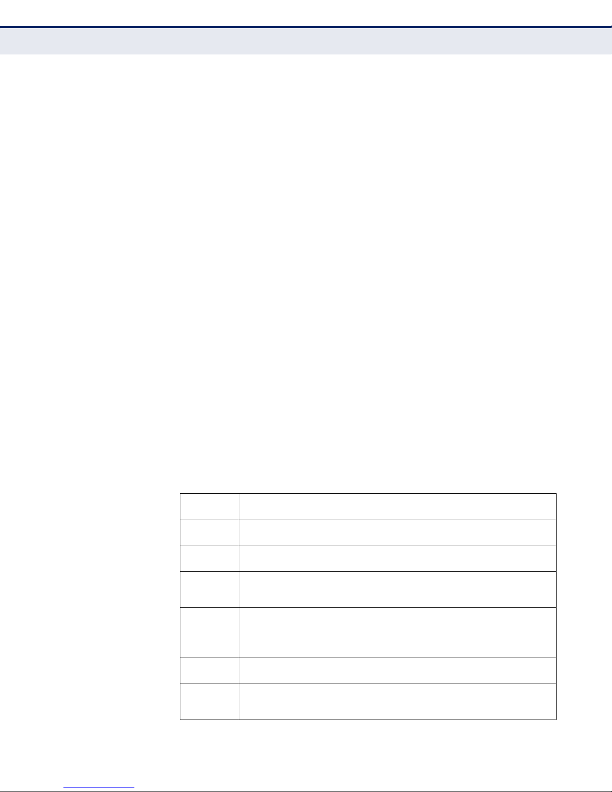
Table 1: Key Hardware Features
Feature Description
WAN Port One 100BASE-TX RJ-45 port for connecting to the Internet.
LAN Port One 100BASE-TX RJ-45 port for local network connections.
USB Port One USB slot for a 3G or 3.5G modem.
WPS Button To set up a secure connection to a wireless device.
Reset Button For resetting the unit and restoring factory defaults.
LEDs Provides LED indicators for Power, WAN port, LAN port, and WLAN
Mounting Options Can be mounted on any horizontal surface such as a desktop or
The wireless 3G Broadband Router package includes:
◆ 802.11b/g/n wireless 3G Broadband Router (
◆ RJ-45 Category 5 network cable
status.
shelf, or on a wall using two screws.
SMCWBR14S-3GN
)
◆ AC power adapter
◆ SMC Warranty Information Card
– 15 –
◆ Quick Installation Guide
◆ EZ Installation & Documentation CD
Inform your dealer if there are any incorrect, missing or damaged parts. If
possible, retain the carton, including the original packing materials. Use
them again to repack the product in case there is a need to return it.
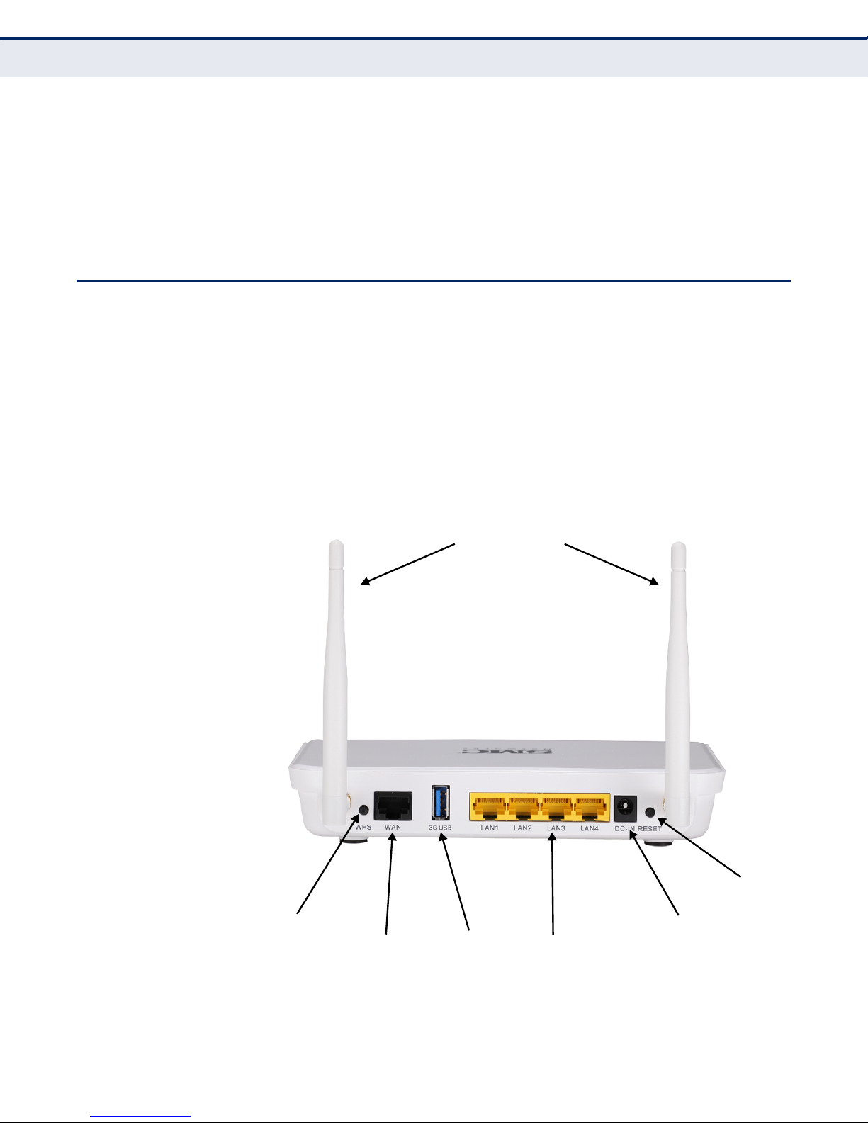
HARDWARE DESCRIPTION
The wireless 3G Broadband Router, from herein refered to as wireless 3G
Broadband Router, connects to the Internet through its RJ-45 WAN port. It
connects directly to your PC or to a local area network using its RJ-45 Fast
Ethernet LAN port.
The wireless 3G Broadband Router includes an LED display on the front
panel for system power and port indications that simplifies installation and
network troubleshooting.
C
HAPTER
1
| Introduction
Hardware Description
Figure 1: Rear Panel
Antennas
Reset Button
WPS Button
Ethernet WAN
RJ-45 Port
– 16 –
3G USB
Slot
Power Socket
Ethernet LAN
RJ-45 Ports
C
HAPTER
1
| Introduction
Hardware Description
ANTENNAS The access point includes integrated MIMO antennas for wireless
communications. A MIMO antenna system uses two or more identical
antennas to receive and transmit signals, helping to increase data
throughput and range. The antennas transmit the outgoing signal as a
toroidal sphere (doughnut shaped), with the coverage extending most in a
direction perpendicular to the antenna. The antenna should be adjusted to
an angle that provides the appropriate coverage for the service area.
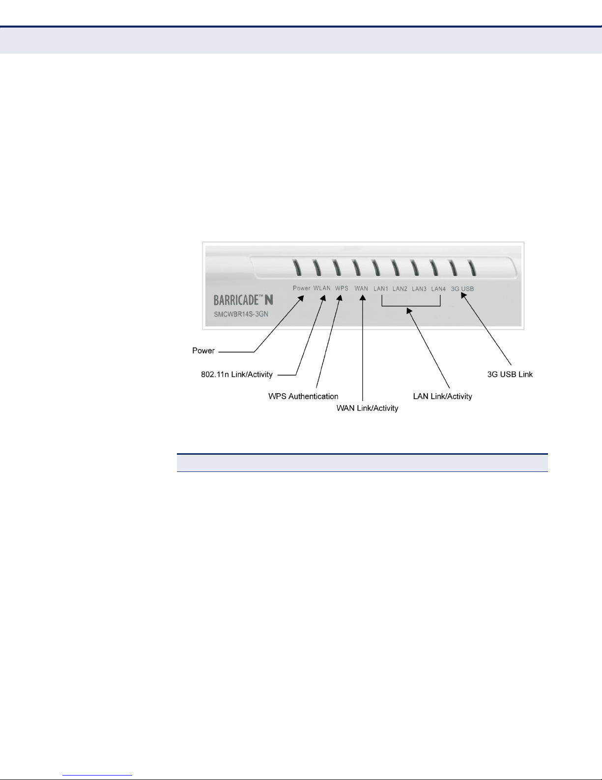
LED INDICATORS The wireless 3G Broadband Router includes four status LED indicators, as
described in the following figure and table.
Figure 2: LEDs
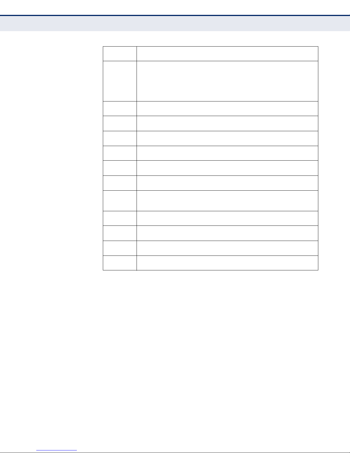
Table 2: LED Behavior
LED Status Description
Power On Blue The unit is receiving power and is operating normally.
Off There is no power currently being supplied to the
WLAN On/Blinking Blue The 802.11n radio is enabled and
Off The 802.11n radio is disabled.
WPS On Blue Indicates the WPS authentication of a device has
Fast Blinking Blue Indicates the WPS authentication of a client device is
Slow Blinking
Off The WPS is not in progress.
unit.
transmitting or receiving data through wireless links.
been successfully completed.
in progress.
If the WPS authentication of a device does not
complete after 120 seconds, the LED changes to Slow
Blinking.
Blue Indicates the WPS authentication of a device did not
complete after 120 seconds. The LED status does not
change until the user restarts or disables the WPS
connection.
– 17 –

C
HAPTER
1
| Introduction
Hardware Description
Table 2: LED Behavior (Continued)
LED Status Description
WAN On Blue The Ethernet WAN port is aquiring an IP address.
Blinking The Ethernet WAN port is connected and is
Off The Ethernet WAN port is disconnected or has
LAN (4 LEDs) On Blue The Ethernet LAN port is connected to a PC or server.
Blinking The Ethernet port is connected and is transmitting or
Off The Ethernet port is disconnected or has
3G USB On Blue A 3G connection has been established.
Slow Blinking A 3G connection is in progress.
Ultra Fast Flashing
Green
Fast Blinking The wrong 3G PIN code has been entered, or the 3G
5 Blinks Cycle The 3G pre-limit budget has been reached.
Off There is no modem connected to the 3G USB port, or
transmitting/receiving data.
malfunctioned.
receiving data.
malfunctioned.
Indicates that 3G usage is already over the ISP
supplied limit.
budget limit has been reached.
the device has failed.
◆ Slow blinking is an on-off cycle of once every 2 seconds.
◆ Fast blinking is an on-off cycle of once of every 0.5 seconds.
◆ Untra Fast flashing is an on-off cycle of once of every 0.2 seconds.
ETHERNET WAN PORT A 100BASE-TX RJ-45 port that can be attached to an Internet access
device, such as a DSL or Cable modem.
ETHERNET LAN PORT The wireless 3G Broadband Router has four 100BASE-TX RJ-45 ports that
can be attached directly to a PC or 10BASE-T/100BASE-TX LAN segments.
These ports support automatic MDI/MDI-X operation, so you can use
straight-through cables for all network connections to PCs, switches, or
hubs.
3G MODEM USB
P
The 3G Modem USB Port supports connection to a wireless cellular 3G or
3.5G modem for broadband Internet access.
ORT
– 18 –

C
HAPTER
1
| Introduction
Hardware Description
POWER CONNECTOR The wireless 3G Broadband Router must be powered with its supplied
power adapter. Failure to do so results in voiding of any warrantly supplied
with the product. The power adapter automatically adjusts to any voltage
between 100~240 volts at 50 or 60 Hz, and supplies 12 volts DC power to
the unit. No voltage range settings are required.
WPS BUTTON Press the WPS button to automatically configure the wireless 3G
Broadband Router with other WPS devices in the WLAN.
RESET BUTTON The Reset button is used to restore the factory default configuration. If you
hold down the button for 5 seconds or more, any configuration changes
you may have made are removed, and the factory default configuration is
restored to the wireless 3G Broadband Router.
– 19 –

2 INSTALLING THE WIRELESS 3G
BROADBAND ROUTER
The wireless 3G Broadband Router has two basic operating modes that can
be set through the web-based management interface. For information on
setting the mode suitable for your network environment. See “Operation
Mode” on page 46
◆ Router Mode — A router mode that connects a wired LAN and wireless
clients to an Internet access device, such as a cable or DSL modem.
This is the factory set default mode.
◆ Bridge Mode — An access point mode that extends a wired LAN to
wireless clients.
In addition to these basic operating modes, the wireless interface supports
a Wireless Distribution System (WDS) link to another wireless 3G
Broadband Router. These advanced configurations are not described in this
section. See “Network Planning” on page 25 for more information.
In a basic configuration, how the wireless 3G Broadband Router is
connected depends on the operating mode. The following sections describe
connections for basic Router Mode and Bridge Mode operation.
SYSTEM REQUIREMENTS
You must meet the following minimum requirements:
◆ An Internet access device (DSL or Cable modem) with an Ethernet port
◆ An up-to-date web browser: Internet Explorer 6.0 or above or Mozilla
connection.
Firefox 2.0 or above.
– 20 –

C
HAPTER
2
| Installing the wireless 3G Broadband Router
Mounting the Device
MOUNTING THE DEVICE
The wireless 3G Broadband Router can be mounted on any horizontal
surface, or on a wall. The following sections describe the mounting options.
MOUNTING ON A WALL The wireless 3G Broadband Router should be mounted only to a wall or
wood surface that is at least 1/2-inch plywood or its equivalent. To mount
the unit on a wall, always use its wall-mounting slots.
To mount on a wall, follow the instructions below.
1. Mark the position of the two screw holes on the wall. For concrete or
brick walls, you will need to drill holes and insert wall plugs for the
screws.
2. Insert two 20-mm M4 tap screws (not included) into the holes, leaving
about 2~3 mm (0.08~0.12 inches) clearance from the wall.
MOUNTING ON A
HORIZONTAL SURFACE
3. Line up the two mounting points on the unit with the screws in the wall,
then slide the unit down onto the screws until it is in a secured position.
To keep the wireless 3G Broadband Router from sliding on the surface, the
unit has four rubber feet on its base.
It is recommended to select an uncluttered area on a sturdy surface, such
as a desktop or table. The unit can also be protected by securing all
attached cables to a table leg or other nearby fixed structure.
– 21 –
ROUTER MODE CONNECTIONS
4.
Set up wireless
devices
Notebook PC
2.
Connect LAN port
to PC
3.
Connect AC power
adapter to
power source
Cable/DSL Modem
1.
Connect WAN port to
cable/DSL modem
Internet
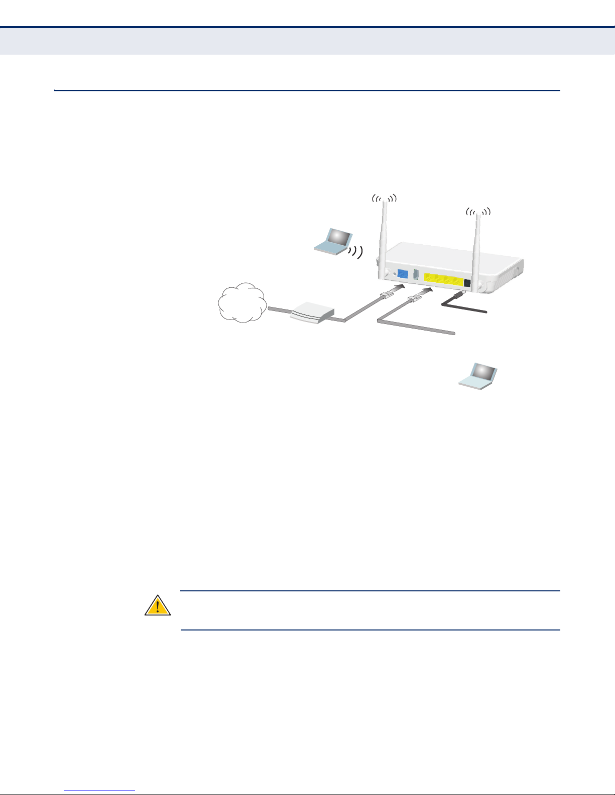
In its default Router Mode, the wireless 3G Broadband Router forwards
traffic between an Internet connected cable or ADSL modem, and wired or
wireless PCs or notebooks. The basic connections are illustrated in the
figure below.
Figure 3: Router Mode Connection
C
HAPTER
2
| Installing the wireless 3G Broadband Router
Router Mode Connections
To connect the wireless 3G Broadband Router in router mode for use as an
Internet gateway, follow these steps:
1. Connect an Ethernet cable from the wireless 3G Broadband Router’s
WAN port to your Internet connected cable or DSL modem.
2. Connect an Ethernet cable from the wireless 3G Broadband Router’s
LAN port to your PC. Alternatively, you can connect to a workgroup
switch to support more wired users. The wireless 3G Broadband Router
can support up to 253 wired and wireless users.
3. Power on the wireless 3G Broadband Router by connecting the AC
power adapter and plugging it into a power source.
C
AUTION
Broadband Router. Otherwise, the product may be damaged.
:
Use ONLY the power adapter supplied with the wireless 3G
When you power on the wireless 3G Broadband Router, verify that the
Power LED turns on and that the other LED indicators start functioning
as described under “LED Indicators” on page 17.
– 22 –
4. Set up wireless devices by pressing the WPS button on the wireless 3G
3.
Set up wireless
devices
Notebook PC
2.
Connect LAN port
to PC
2.
Connect AC power
adapter to
power source
1.
Connect LAN and WAN
ports to an Ethernet LAN
switch or PCs
Broadband Router or by using the web interface. See “Initial
Configuration” on page 29 for more information on accessing the web
interface.
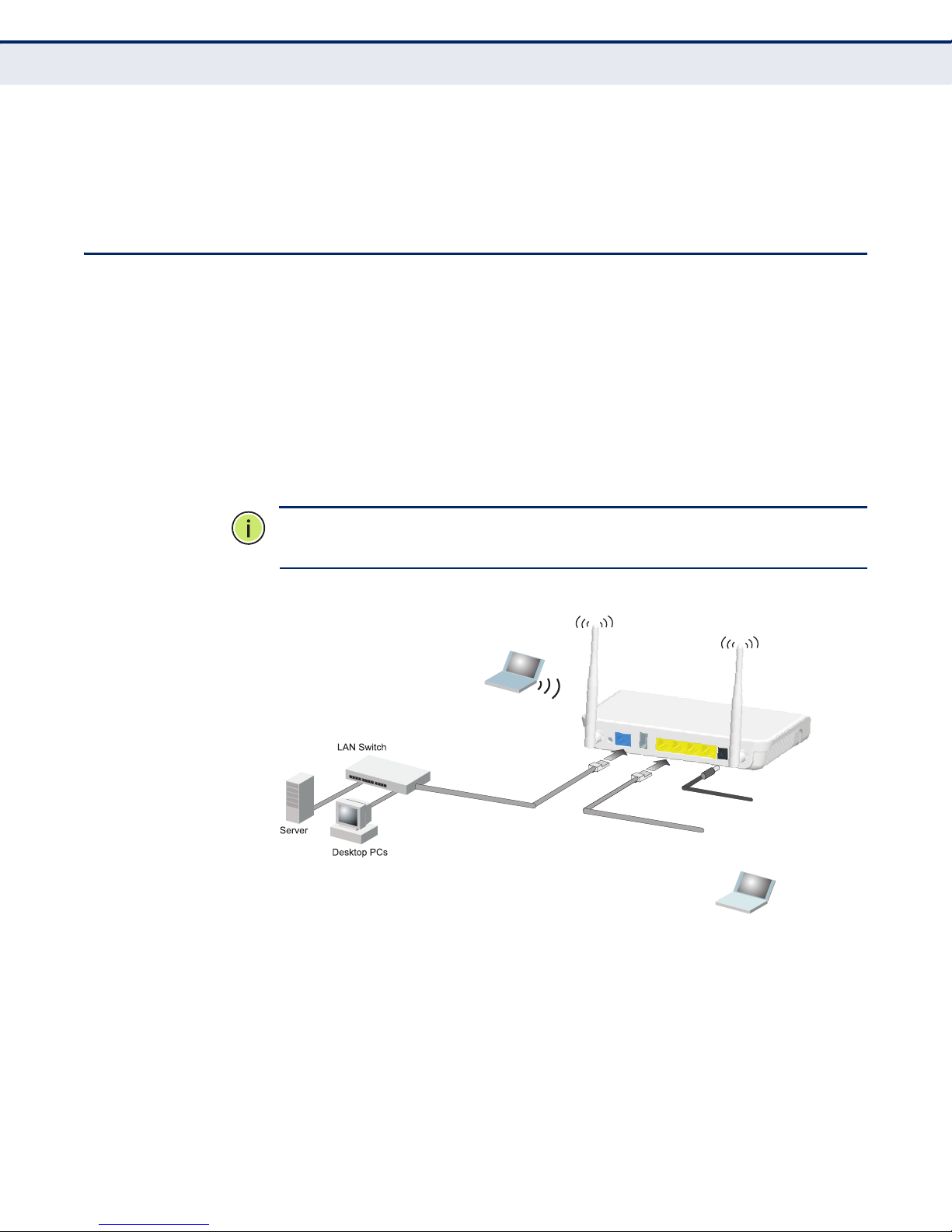
BRIDGE MODE CONNECTIONS
In Bridge Mode, the wireless 3G Broadband Router operates as a wireless
access point, extending a local wired network to associated wireless clients
(PCs or notebooks with wireless capability). From any nearby location, you
can then make a wireless connection to the wireless 3G Broadband Router
and access the wired network resources, including local servers and the
Internet.
In Bridge Mode, the wireless 3G Broadband Router does not support
gateway functions on its WAN port. Both the LAN port and the WAN ports
can be connected to a local Ethernet LAN.
C
HAPTER
2
| Installing the wireless 3G Broadband Router
Bridge Mode Connections
N
OTE
:
Bridge Mode is not the factory default mode and must be manually
set using the web management interface.
Figure 4: Bridge Mode Connection
To connect the wireless 3G Broadband Router for use as an access point,
follow these steps:
1. Using Ethernet cable connect the wireless 3G Broadband Router’s LAN
and WAN ports to PCs. Alternatively, you can connect to a workgroup
switch to support more wired users.
2. Power on the wireless 3G Broadband Router by connecting the AC
power adapter and plugging it into a power source.
– 23 –

C
C
AUTION
HAPTER
:
Use ONLY the power adapter supplied with the wireless 3G
2
| Installing the wireless 3G Broadband Router
Bridge Mode Connections
Broadband Router. Otherwise, the product may be damaged.
When you power on the wireless 3G Broadband Router, verify that the
Power LED turns on and that the other LED indicators start functioning
as described under “LED Indicators” on page 17.
3. Set up wireless devices by pressing the WPS button on the wireless 3G
Broadband Router or by using the web interface. See “Initial
Configuration” on page 29 for more information on accessing the web
interface.
– 24 –
3 NETWORK PLANNING
Wireless AP/Router
Server
(IP: 192.168.2.x)
Desktop PC
(IP: 192.168.2.x)
Cable/DSL
Modem
Internet
Service
Provider
Notebook PC
(IP: 192.168.2.x)
WAN (IP assigned from ISP)
LAN (IP: 192.168.2.x)
LAN Switch
3G
Modem
3G Internet
Service
Provider
The wireless 3G Broadband Router is designed to be very flexible in its
deployment options. It can be used as an Internet gateway for a small
network, or as an access point to extend an existing wired network to
support wireless users. It also supports use as a wireless bridge to connect
two wired LANs.
This chapter explains some of the basic features of the wireless 3G
Broadband Router and shows some network topology examples in which
the device is implemented.
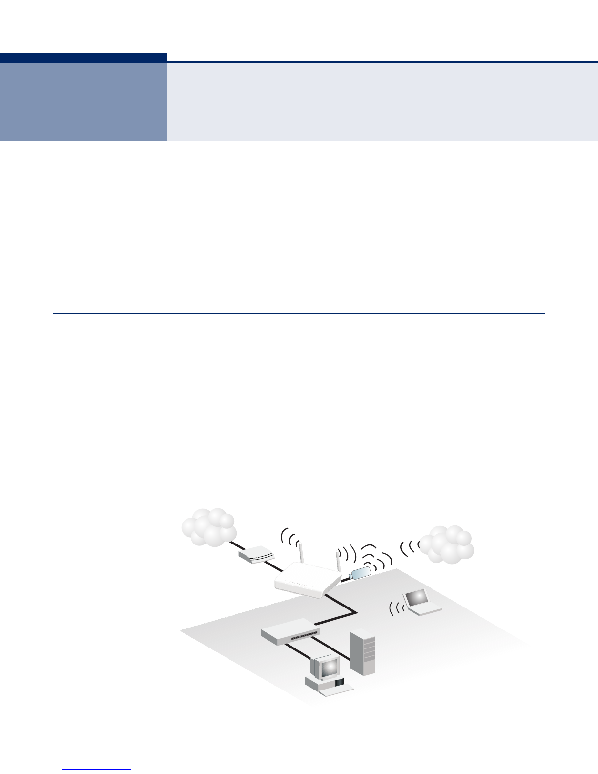
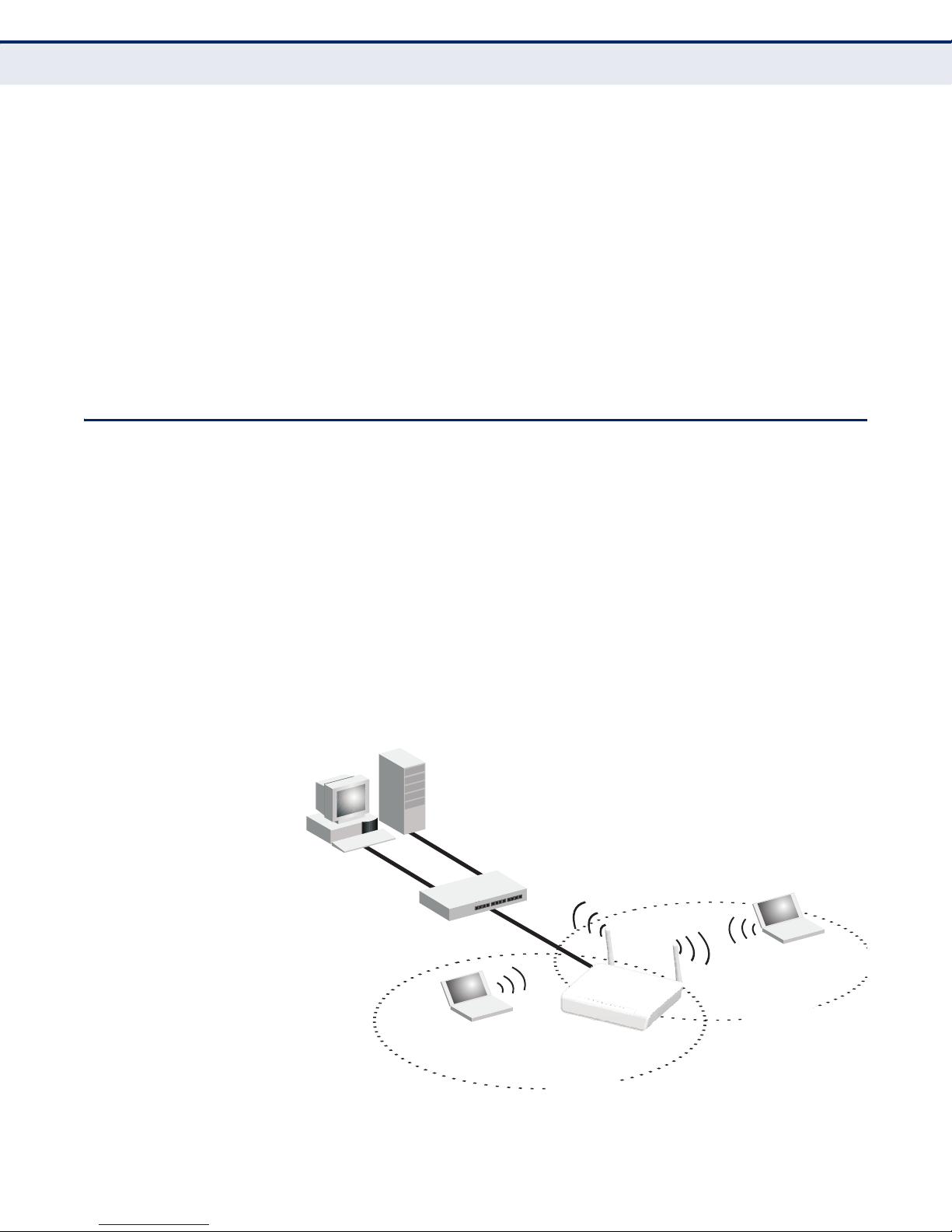
INTERNET GATEWAY ROUTER
The wireless 3G Broadband Router can connect directly to a cable or DSL
modem to provide an Internet connection for multiple users through a
single service provider account. Users connect to the wireless 3G
Broadband Router either through a wired connection to a LAN port, or
though the device’s own wireless network. The wireless 3G Broadband
Router functions as an Internet gateway when set to Router Mode.
An Internet gateway employs several functions that essentially create two
separate Internet Protocol (IP) subnetworks; a private internal network
with wired and wireless users, and a public external network that connects
to the Internet. Network traffic is forwarded, or routed, between the two
subnetworks.
Figure 5: Operating as an Internet Gateway Router
– 25 –
LAN ACCESS POINT
Server
(IP: 192.168.2.x)
Desktop PC
(IP: 192.168.2.x)
LAN Switch
Notebook PC
(IP: 192.168.2.x)
SSID 1
(public)
Notebook PC
(IP: 192.168.2.x)
SSID 2
(private)
Wireless AP/Router
C
HAPTER
3
| Network Planning
LAN Access Point
The private local network, connected to the LAN port or wireless interface,
provides a Dynamic Host Configuration Protocol (DHCP) server for
allocating IP addresses to local PCs and wireless clients, and Network
Address Translation (NAT) for mapping the multiple "internal" IP addresses
to one "external" IP address.
The public external network, connected to the WAN port, supports DHCP
client, Point-to-Point Protocol over Ethernet (PPPoE), static IP for
connection, L2TP and PPTP to an Internet service provider (ISP) through a
cable or DSL modem.
The 3G Modem link can provide a backup Internet connection with
automatic failover and fallback to the primary WAN connection.
The wireless 3G Broadband Router can provide an access point service for
an existing wired LAN, creating a wireless extension to the local network.
The wireless 3G Broadband Router functions as purely an access point
when set to Bridge Mode. When used in this mode, there are no gateway
functions between the WAN port and the LAN and wireless interface.
A Wi-Fi wireless network is defined by its Service Set Identifier (SSID) or
network name. Wireless clients that want to connect to a network must set
their SSID to the same SSID of the network service. The wireless 3G
Broadband Router supports two separate wireless interfaces, that is two
SSIDs or Virtual Access Points (VAPs). The two VAP interfaces can be
configured separately to support different security settings or other
wireless functions.
Figure 6: Operating as an Access Point
– 26 –
WIRELESS CLIENT
Cable/DSL
Modem
Internet
Service
Provider
Wireless AP/Router
Server
(IP: 192.168.2.x)
Desktop PC
(IP: 192.168.2.x)
Notebook PC
(IP: 192.168.2.x)
Wireless Client WAN
(IP from external network)
LAN Port
(IP: 192.168.2.x)
LAN Switch
Access Point
(External SSID)
C
HAPTER
3
| Network Planning
Wireless Client
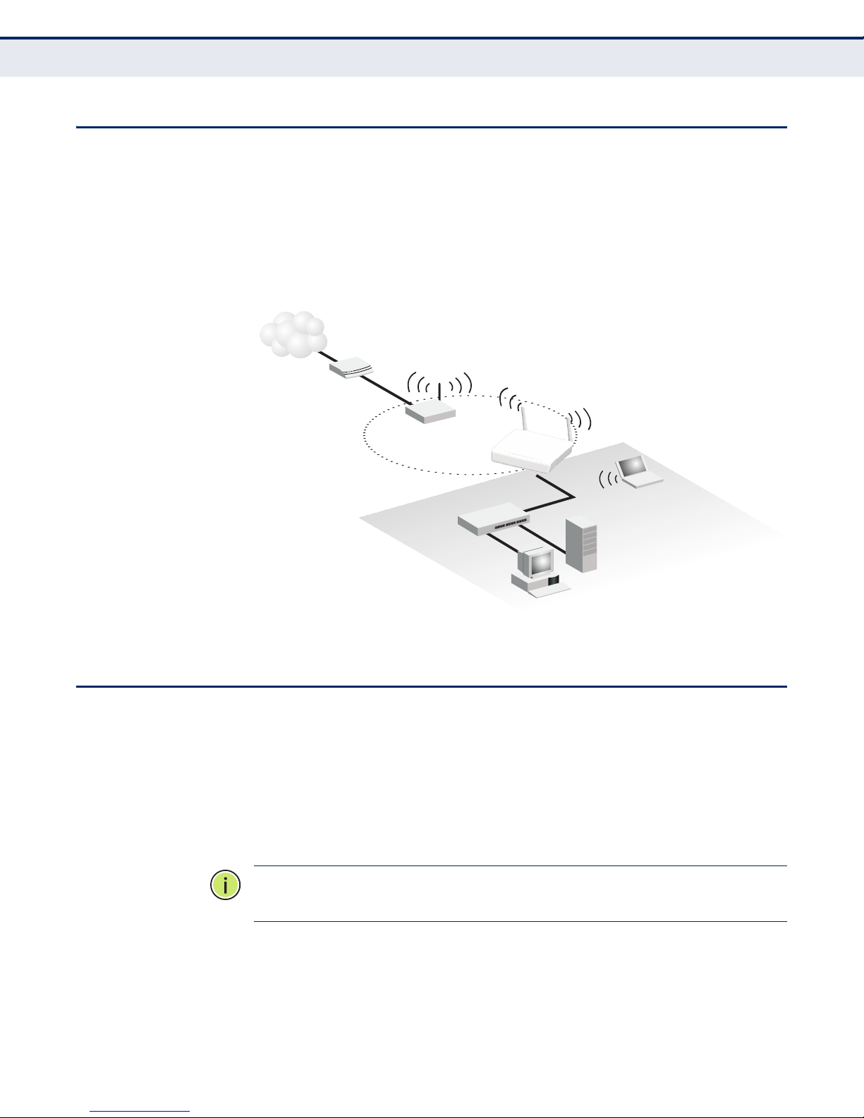
The wireless 3G Broadband Router can operate as a wireless client on one
VAP interface, which enables a connection to another Wi-Fi network. When
the wireless client option is enabled as a WAN connection, the client VAP
interface functions as an external gateway WAN port. When the wireless
client option is enabled as a LAN connection, the other VAP interface and
LAN ports all function as the local network within the same IP subnet.
Figure 7: Operating with a Wireless Client WAN Connection
WIRELESS BRIDGE
The IEEE 802.11 standard defines a Wireless Distribution System (WDS)
for bridge connections between access points. The wireless 3G Broadband
Router can use WDS to forward traffic on links between units.
A single WDS bridge link can be specified for the WLAN1 interface. One end
of a link must be configured as the “WDS Parent” and the other as the
“WDS Child.”
N
OTE
parent.
:
The network domain of WDS child has to be the same as WDS
– 27 –
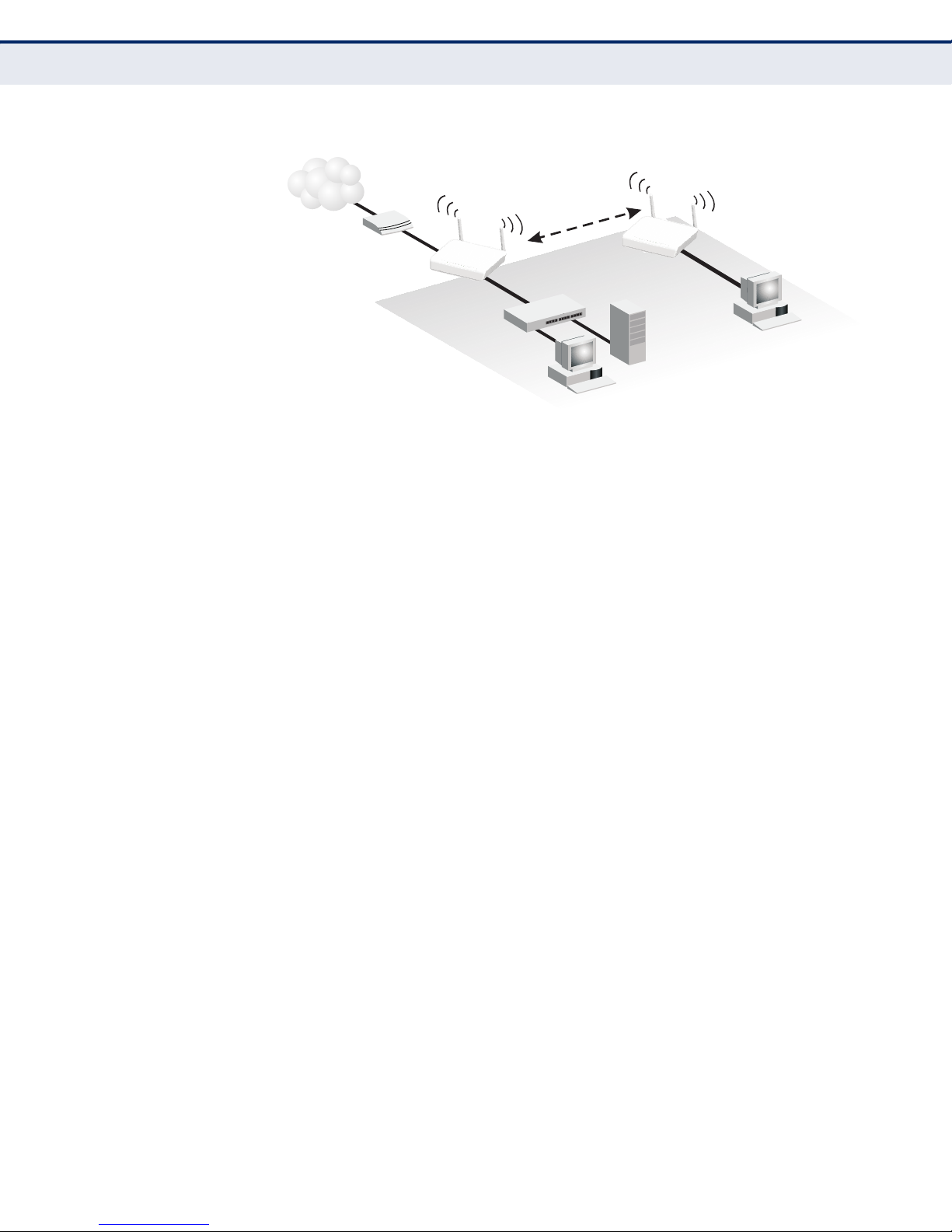
Figure 8: Operating as a Wireless Bridge
Wireless AP/Router
(Gateway Mode)
Server
(IP: 192.168.2.x)
Desktop PC
(IP: 192.168.2.x)
Cable/DSL
Modem
Internet
Service
Provider
WAN
(IP from ISP)
LAN
(IP: 192.168.2.x)
LAN Switch
Desktop PC
(IP: 192.168.2.x)
WDS Child
WDS Parent
WDS Link
Wireless AP/Router
(Bridge Mode)
C
HAPTER
3
| Network Planning
Wireless Bridge
– 28 –

4 INITIAL CONFIGURATION
The wireless 3G Broadband Router offers a user-friendly web-based
management interface for the configuration of all the unit’s features. Any
PC directly attached to the unit can access the management interface using
a web browser, such as Internet Explorer (version 6.0 or above).
ISP SETTINGS
If you are not sure of your connection method, please contact your
Internet Service Provider. There are several connection types to choose
from: Static IP, DHCP (cable connection), PPPoE (DSL connection), PPTP,
L2TP and 3G.
N
OTE
:
If using the PPPoE option, you will need to remove or disable any
PPPoE client software on your computers.
CONNECTING TO THE LOGIN PAGE
It is recommended to make initial configuration changes by connecting a
PC directly to the wireless 3G Broadband Router’s LAN port. The wireless
3G Broadband Router has a default IP address of 192.168.2.1 and a subnet
mask of 255.255.255.0. You must set your PC IP address to be on the
same subnet as the wireless 3G Broadband Router (that is, the PC and
wireless 3G Broadband Router addresses must both start 192.168.2.x).
To access the wireless 3G Broadband Router’s management interface,
follow these steps:
1. Use your web browser to connect to the management interface using
the default IP address of 192.168.2.1.
2. Log into the interface by entering the default username “admin” and
password “smcadmin,” then click OK.
N
OTE
:
It is strongly recommended to change the default password the first
time you access the web interface. For information on changing passwords,
See “System Management” on page 98.
– 29 –
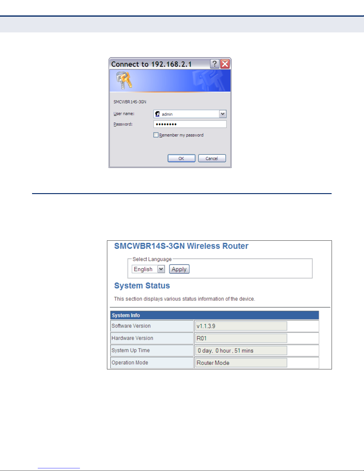
Figure 9: Login Page
C
HAPTER
4
| Initial Configuration
Home Page and Main Menu
HOME PAGE AND MAIN MENU
After logging in to the web interface, the Home page displays. The Home
page shows the main menu and the method to access the Setup Wizard.
Figure 10: Home Page
– 30 –
 Loading...