

SMC Networks VXS23, VXS26, VXS25, VXS24 Installation And Maintenance Manual
VXSS-TFR48
Installation and Maintenance Manual
VXS Zero Pressure Differential Type
Pilot operated 2 port solenoid valve
For Steam and Heated water
1 Safety Instructions
This manual contains essential information for the protection of users and
others from possible injury and/or equipment damage.
• Read this manual before using the product, to ensure correct handling,
and read the manuals of related apparatus before use.
• Keep this manual in a safe place for future reference.
• These instructions indicate the level of potential hazard by label of
“Caution”, “Warning” or “Danger”, followed by important safety
information which must be carefully followed.
• To ensure safety of personnel and equipment the safety instructions in
this manual and the product catalogue must be observed, along with
other relevant safety practices.
Caution
Indicates a hazard with a low level of risk, which if not
avoided, could result in minor or moderate injury.
Warning
Indicates a hazard with a medium level of risk, which
if not avoided, could result in death or serious injury.
Danger
Indicates a hazard with a high level of risk, which if
not avoided, will result in death or serious injury.
Warning
• The compatibility of equipment is the responsibility of the person
who designs the system or decides its specifications.
Since the products specified here can be used in various operating
conditions, their compatibility with a specific system must be based on
specifications or after analysis and/or tests to meet specific
requirements.
• Only trained personnel should operate pneumatically operated
machinery and equipment.
The fluid can be dangerous if an operator is unfamiliar with it. Assembly,
handling or repair of the system should be performed by trained and
experienced personnel.
• Do not service machinery/equipment or attempt to remove
components until safety is confirmed.
1) Inspection and maintenance of machinery/equipment should only be
performed after confirmation of s afe locked-out control positions.
Measures to prevent danger from the fluid should also be taken.
2) When equipment is to be removed, confirm the safety processes as
mentioned above. Release the fluid pressure and be certain there is no
danger from fluid leakage or fluid remaining in the system. Switch off
electrical supplies.
3) Before machinery/equipment is re-started, ensure all safety measures
are being implemented.
• Do not use this product outside of the specifications. Contact SMC
if it is to be used in any of the following conditions:
1) Conditions and environments beyond the given specifications, or if the
product is to be used outdoors.
2) Installations in conjunction with atomic energy, railway, air na vigation,
vehicles, medical equipment, food and beverage, recreation equipment,
emergency stop circuits, press applications, or safety equipment.
3) An application which has the possibility of having negative effects on
people, property, or animals, requiring special safety analysis.
Caution
• Ensure that the air supply system is filtered to 5 m.
2 Specifications
2.1 General Specifications
Valve
specifications
Valve construction
Zero differential pressure pilot operated 2
port piston type
Withstand pressure (with
water)
2.0 MPa
Maximum system pressure
1.0 MPa
Maximum operating
pressure differential
1.0 MPa
Minimum operating
pressure differential
0 MPa
Note 1)
Body material
Brass (C37), Stainless steel
Seal material
(Note 3)
FKM
Enclosure
Dust-tight, Water jet-proof type (IP65)
Environment
Location without corrosive or explosive
gases
Coil
specifications
Rated voltage
AC
100 VAC, 200VAC, 110VAC, 230VAC,
(220VAC, 240VAC, 48VAC, 24VAC)
Note 2)
DC
24 VDC
Allowable voltage fluctuation
±10% of rated voltage
Allowable leakage
voltage
AC
5% or less of rated voltage
DC
2% or less of rated voltage
Coil insulation type
Class H
Note 1) The operation of the valve may be unstable due to the capacity of the
pressure supply source such as pumps and compressors or the pressure loss by the
orifice of piping. Please contact SMC to check if the required valve size can be used
in the application. Contact SMC for the compatibility of the circuit and valve size.
Note 2) Voltage in brackets ( ) indicates special voltage.
2.2 Coil Specifications
2.2.1 Normally Closed (N.C.)
DC Specification
Model
Power consumption (W)
Note1)
Temperature rise (°C)
Note2)
VXS23/24
12
100
VXS25/26
15
100
Note 1: Power consumption: The value at ambient temperature of 20°C and when the
rated voltage is applied. (Variation: ±10%).
Note 2: The value at ambient temperature of 20°C and when the rated voltage is
applied. The value depends on the ambient environment. This is for reference.
2.2.2 Normally Closed (N.C.)
AC Specification (Built-in Full-wave Rectifier Type)
Model
Apparent power (VA)
Note 1, 2)
Temperature rise (°C)
Note 3)
VXS23/24
12
100
VXS25/26
15
100
Note 1: Power consumption, apparent power: The value at ambient temperature of
20°C and when the rated voltage is applied. (Variation: ±10%)
Note 2: There is no difference in the frequency and the inrush and energized apparent
power, since a rectifying circuit is used for AC. (Built-in full-wave rectifier type).
Note 3: The value at ambient temperature of 20°C and when the rated voltage is
applied. The value depends on the ambient environment. This is for reference.
2.3 Model/Valve specifications
For STEAM / Single Unit (Can be used with heated water)
Normally closed (N.C.)
C37, Stainless steel body
Size
Port
Size
Orifice
Dia.
(mm)
Model
Flow characteristics
Weight
Note)
(g)
Av
(x 10-6 m2)
Cv
3
1/4
10
VXS235
58
2.4
600
3/8
67
2.8
4
1/2
15
VXS245
130
5.3
720
5
3/4
20
VXS255
220
9.2
1100
6 1 25
VXS265
290
12.0
1300
Note) Weight of Grommet type. Add 10g for Conduit type, 30g for DIN terminal, 60g
for Conduit terminal type.
Ambient and fluid temperature
Fluid
Temperature (°C)
Ambient temperature (°C)
Steam
183 or less
-20 to 60
Heated water
99 or less
Note) With no freezing.
2 Specifications (continued)
Valve Internal Leakage Rate
Fluid
Seal Material
Leakage rate
Note)
Steam
FKM
1 cm3/min or less
Heated water
0.1 cm3/min or less
Valve External Leakage Rate
Fluid
Seal Material
Leakage rate
Note)
Steam
FKM
1 cm3/min or less
Heated water
0.1 cm3/min or less
Note) Leakage is the value at ambient temperature 20°C.
2.4 Pneumatic Symbol
2.4.1 Valve
Valve
Symbol
Normally closed (N.C.)
Table 1
3 Installation
Warning
• Do not install the product unless the safety instructions have been read
and understood.
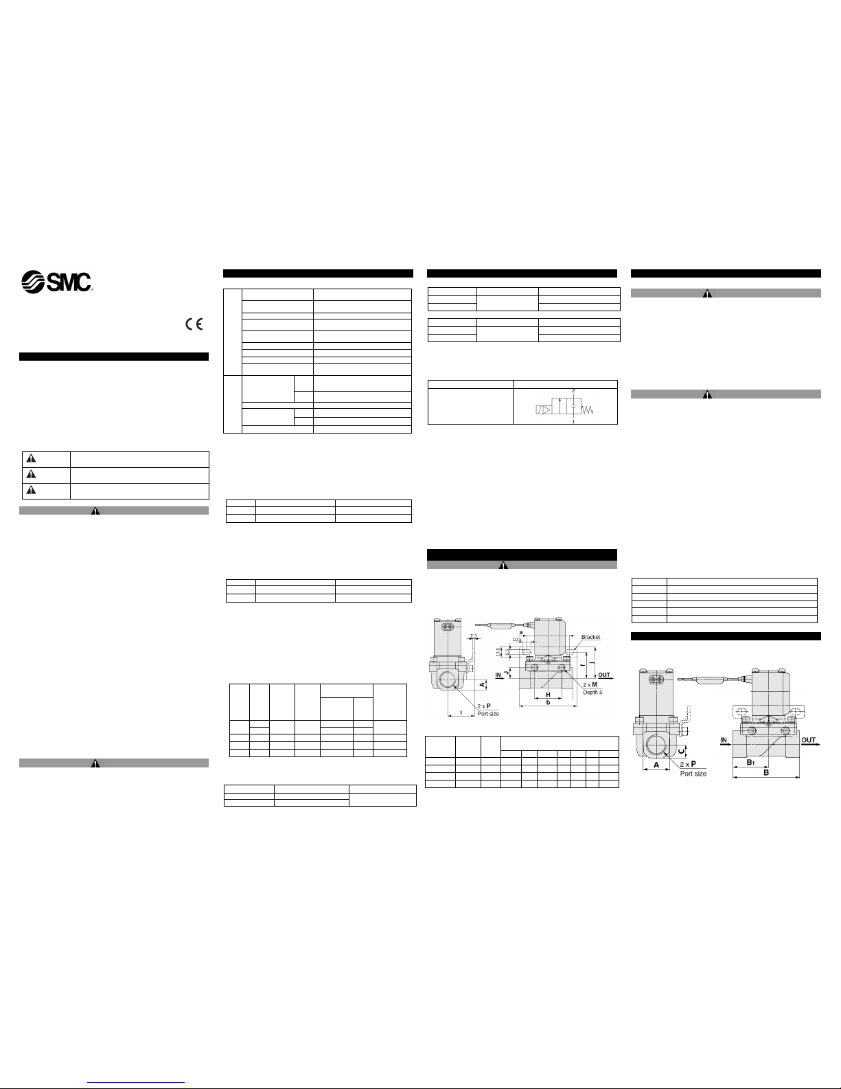
3.1 VXS Valve Mounting Bracket
C37, Stainless steel (Bracket optional)
Figure 1
Model
Port
size
P
A
(mm)
Bracket Mounting
(mm)
a b f i j H J
VXS23
1/4, 3/8
10.5
56
75
30
31
37
35
10
VXS24
1/2
14
56
75
34
35
41
35
14
VXS25
3/4
17
70.5
92
39
43
46
33
15.2
VXS26 1 20
70.5
92
41
45
48
37
17.2
Table 2
3 Installation (continued)
3.2 Environment
Warning
• Do not use in an environment where corrosive gases, chemicals, salt
water, water, water vapour are present or where there is direct contact
with any of these.
• Do not use in an explosive atmosphere.
• Do not expose to direct sunlight. Use a suitable protective cover.
• Do not install in a location subject to vibration or impact. Check the
product specifications.
• Do not mount in a location exposed to radiant heat.
• Employ suitable protective measures in locations where there is contact
with water droplets, oil or welding splatter, etc.
3.3 Piping
Caution
• Before connecting piping, it should be thoroughly blown out with air
(flushed) or washed to remove chips, cutting oil and other debris from
inside the pipe.
• Avoid connecting ground lines to piping, as this may cause electrolytic
corrosion of the system.
• When installing piping or fittings, ensure sealant material does not enter
inside the port. When using seal tape, leave 1.5 to 2 threads exposed on
the end of the pipe/fitting.
• Tighten fittings to the specified tightening torque, see Table 3.
• Install piping s o that it does not apply pulling, pressing, bending or other
forces on the valve body.
• When connecting piping, avoid mistakes regarding the supply port.
• Steam generated by a boiler contains a large amount of drainage;
ensure to operate with a drain trap installed.
• Avoid installing piping to the valve at the lowest point of the layout. If
condensate accumulates in the valve or adjacent piping, this could
cause steam hammer. If steam hammer causes a problem, install a
bypass to discharge condensate from the piping.
• If the effective area of the piping on the fluid supply side is restricted, the
operating time m ay become unstable due to the differential pressure
fluctuation when the valve is closed.
Thread
Tightening Torque N•m
Rc 1/4
12 to 14
Rc 3/8
22 to 24
Rc 1/2
28 to 30
Rc 3/4
28 to 30
Rc 1
36 to 38
Table 3
3 Installation (continued)
3.3.1 Valve Ports
C37, Stainless steel
Figure 2
VXSS-TFR48
3 Installation (continued)
Model
Port size P
(Rc)
Valve Ports
(mm)
A B B1 C VXS23
1/4, 3/8
21
57
28.5
10.5
VXS24
1/2
28
70
37.5
14
VXS25
3/4
33.5
71
38.5
17
VXS26 1 42
95
49.5
20
Table 4
3.4 Electrical connection
Caution
• Avoid mis-wiring, as this can cause malfunction, damage and fire to the
product.
• To prevent noise and surge in signal lines, keep all wiring separate from
power lines and high voltage lines. Otherwise this can cause
malfunction.
• When a surge from the solenoid affects the electrical circuitry, install a
surge absorber, etc., in parallel with the solenoid. Or, use an option that
comes with surge voltage protection circuit.
• Use electrical circuits that do not generate chattering in their contacts.
• Use voltage that is within ±10% of the rated voltage. In cases with a DC
power supply where responsiveness is important, stay within ±5% of the
rated value. (The voltage drop is the value in the lead wire section
connecting the coil).
• Generally use electrical wire with cross sectional area 0.5 to 1.25 mm2.
• Do not bend or pull cables repeatedly.
• Do not allow excessive force to be applied to the lines.
• Do not apply AC voltage to AC type unless it has a built in full-wave
rectifier or it will be damaged.
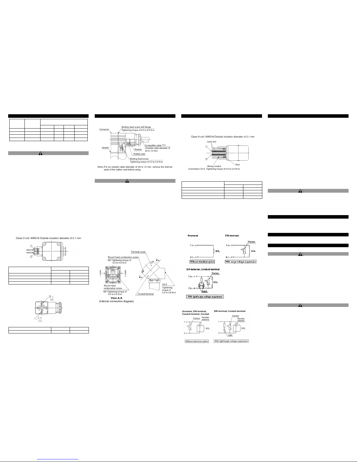
3.4.1 Grommet
Figure 3
Rated Voltage
Lead wire colour
1
2
DC
Black
Red
100 VAC
Blue
Blue
200 VAC
Red
Red
Other AC
Grey
Grey
*There is no polarity
Table 5
3.4.2 DIN Terminal
Figure 4
Terminal no.
1
2
Din Terminal
+(-)
-(+)
*There is no polarity
Table 6
• Use a heavy-duty cord with an outside cable diameter of Ø6 to 12 mm.
• Tighten screws and fittings according to Figure 5.
3 Installation (continued)
Figure 5
Caution
• For class H coil, surge voltage suppressor and full-wave rectifier (for AC)
are on DIN connector side. A SMC DIN connector must be used. Part
numbers can be found in product catalogue.
3.4.3 Conduit Terminal
• Make connections according to the marking shown in Figure 6.
• Tighten screws and fittings according to Figure 6.
• Properly seal the terminal connection (G1/2) with special wiring conduit,
etc.
Figure 6
3 Installation (continued)
3.4.4 Conduit
• When used as an IP65 equivalent use seal (VCW20-15-6) to install the
wiring conduit.
• Tighten conduit to torque shown in Figure 7.
Figure 7
Rated Voltage
Lead wire colour
1
2
DC
Black
Red
100 VAC
Blue
Blue
200 VAC
Red
Red
Other AC
Grey
Grey
*There is no polarity
(For the power saving type, there is polarity)
Table 7
3.5 Electrical circuits
3.5.1 DC circuit
Figure 8
3.5.2 AC circuit
Figure 9
3 Installation (continued)
3.6 Mounting
• Secure with brackets, except in the case of steel piping and copper
fittings.
• Avoid sources of vibration, or adjust the distance from the body to a
minimum length so that resonance will not occur.
• If air leakage increases or equipment does not operate properly, stop
operation. After mounting is completed, confirm that it has been done
correctly by performing a suitable function test.
• Do not apply external force to the coil section:
When tightening fittings, apply a wrench or other tool to the outside of
the piping connection parts.
• Do not install with the coil downwards.
If a valve is mounted with the coil positioned downwards, foreign objects
in the fluid will adhere to the iron core leading to a malfunction.
• Do not warm the coil assembly with a heat insulator, etc.
Use tape, heaters, etc., for freeze prevention on the piping and body
only. They can cause the coil to burn out.
• Painting and coating:
Warnings or specifications printed or labeled on the product should not
be erased, removed or covered up.
3.7 Lubrication
Caution
• SMC products have been lubricated for life at manufacture, and do not
require lubrication in service.
• If a lubricant is used in the system, use turbine oil Class 1 (no additive),
ISO VG32.
• Once lubricant is used in the system, lubrication must be continued
because the original lubricant applied during manufacturing will be
washed away.
4 How to Order
Refer to the catalogue for this product.
5 Outline Dimensions (mm)
Refer to the catalogue for this product.
6 Maintenance
6.1 General Maintenance
Caution
• Not following proper maintenance procedures could cause the product to
malfunction and lead to equipment damage.
• If handled improperly, compressed air can be dangero us. Maintenance
of pneumatic systems should be performed only by qualified personnel.
• Before performing maintenance, turn off the power supply and be sure to
cut off the supply pressure. Confirm that the air is released to
atmosphere.
• After installation and maintenance, apply operating pressure and power
to the equipment and perform appropriate functional and leakage tests
to make sure the equipment is installed correctly.
• Do not make any modification to the product.
• Do not disassemble the product, unless required by installation or
maintenance instructions.
• Exhaust the drainage from the piping periodically.
Warning
6.2 Removing the product:
• The valve will reach a high temperature when used with high
temperature fluids. Confirm that the valve temperature has dropped
sufficiently before performing work. If touched inadvertently, there is
danger of being burned.
1. Shut off the fluid supply and release the fluid pressure in the
system.
2. Shut off the power supply.
3. Remove the valve, ensuring any seals are retained.
 Loading...