

SMC Networks VX21, VX22, VX23, VVX21, VVX22 Installation And Maintenance Manual
...
Installation and Maintenance Manual
VX21/22/23, 2 Port Solenoid Valves and
VVX21/22/23, Manifold Series
This manual should be read in conjunction with the current catalogue
For future reference, please keep this manual in a safe place
Safety Instructions
These safety instructions are intended to prevent a hazardous situation and/or equipment damage.These instructions indicate the level
of potential hazard by label of “Caution”,“Warning” or “Danger”.
To ensure safety,be sure to observe ISO4414
(Note1)
, JIS B 8370
(Note2)
and other safety practices.
Note 1: ISO 4414:Pneumatic fluid power – Recommendations for the
application of equipment to transmission and control systems.
Note 2: JIS B 8370: Pneumatic system axiom.
CAUTION : Operator error could result in injury or
equipment damage.
WARNING: Operator error could result in serious
injury or loss of life.
DANGER : In extreme conditions, there is a
possible result of serious injury or loss of life.
WARNING
1. The compatibility of pneumatic equipment is the responsibility of the person who designs the pneumatic system
or decides its specifications.
Since the products specified here are used in various operating
conditions, their compatibility for the specific pneumatic system
must be based on specifications or after analysis and/or tests to
meet your specific requirements.
2. Only trained personnel should operate pneumatically
operated machinery and equipment.
Compressed air can be dangerous if an operator is unfamiliar
with it.Assembly, handling or repair of pneumatic systems should
be performed by trained and experienced operators.
3. Do not service machinery/equipment or attempt to
remove component until safety is confirmed.
1) Inspection and maintenance of machinery/equipment should
only be performed after confirmation of safe locked-out
control positions.
2) When equipment is to be removed, confirm the safety process
as mentioned above.Switch off air and electrical supplies and
exhaust all residual compressed air in the system.
3) Before machinery/equipment is re-started, ensure all safety
measures to prevent sudden movement of cylinders etc.
(Bleed air into the system gradually to create back-pressure,
i.e. incorporate a soft-start valve).
4. Contact SMC if the product is to be used in any of the
following conditions:
1) Conditions and environments beyond the given specifica-
tions, or if product is used outdoors.
2) Installations in conjunction with atomic energy, railway, air
navigation, vehicles,medical equipment, food and beverage,
recreation equipment, emergency stop circuits, press
applications, or safety equipment.
3) An application which has the possibility of having negative
effects on people, property, or animals, requiring special
safety analysis.
CAUTION
Ensure that the air supply system is filtered to 5 micron.
Type/Valve specifications (Energised open type)
Flow rate
Max. operating pressure Max
Orifice differential MPa (kgf/cm
2
) system Proof Weight
Port size Effective
Model
pressure pressure (g)
size (mmø) Cv area Water Air Oil Steam MPa MPa (Note)
(mm
2
) (kgf/cm2) (kgf/cm2)
AC DC AC DC AC DC AC
1
/
8
2 0.17 3 VX2110-01 2.0{20} 1.5{15} 2.0{20} 1.5{15} 1.5{15} 1.5{15} 1.0{10}
(6A) 3 0.33 6 VX2120-01 0.9{9} 0.5{5} 1.1{11} 0.6{6} 0.5{5} 0.5{5} 1.0{10}
4.5 0.61 11 VX2130-01 0.4{4} 0.2{2} 0.45{4.5} 0.2{2} 0.2{2} 0.15{1.5} 0.45{4.5} 260
2 0.17 3 VX2110-02 2.0{20} 1.5{15} 2.0{20} 1.5{15} 1.5{15} 1.5{15} 1.0{10} Water
VX2120-02 0.9{9} 0.5{5} 1.1{11} 0.6{6} 0.5{5} 0.5{5} 1.0{10} Oil
3 0.33 6 VX2220-02 1.7{17} 1.5{15} 2.0{20} 1.5{15} 1.2{12} 1.2{12} 1.0{10} Air 5.0 400
VX2320-02 2.5{25} 3.0{30} 3.0{30} 3.0{30} 1.7{17} 2.0{20} - 3.0 {50} 540
VX2130-02 0.4{4} 0.2{2} 0.45{4.5} 0.2{2} 0.2{2} 0.15{1.5} 0.45{4.5} {30} 260
1
/
4
4.5 0.61 11 VX2230-02 0.6{6} 0.35{3.5} 0.75{7.5} 0.35{3.5} 0.35{3.5} 0.3{3} 0.75{7.5} Steam 400
(8A) VX2330-02 0.85{8.5} 0.9{9} 1.0{10} 0.9{9} 0.55{5.5} 0.85{8.5} 1.0{10} 1.0 540
6 1.05 19 VX2240-02 0.35{3.5} 0.15{1.5} 0.4{4} 0.15{1.5} 0.2{2} 0.1{1} 0.4{4} {10} 400
VX2340-02 0.55{5.5} 0.3{3} 0.5{5} 0.35{3.5} 0.35{3.5} 0.3{3} 0.5{5} 540
8 1.7 31 VX2250-02 0.13{1.3} 0.08{0.8} 0.15{1.5} 0.08{0.8} 0.1{1} 0.08{0.8} 0.15{1.5} Water· 510
VX2350-02 0.17{1.7} 0.2{2} 0.2{2} 0.2{2} 0.14{1.4} 0.2{2} 0.2{2} Oil Air 3.0 650
10 1.9 34 VX2260-02 0.08{0.8} 0.03{0.3} 0.08{0.8} 0.03{0.3} 0.05{0.5} 0.03{0.3} 0.08{0.8} 1.0 {10} {30} 510
VX2360-02 0.1{1} 0.07{0.7} 0.1{1} 0.07{0.7} 0.08{0.8} 0.07{0.7} 0.1{1}
Steam 0.5 {5}
650
3 0.33 6 VX2220-03 1.7{17} 1.5{15} 2.0{20} 1.5{15} 1.2{12} 1.2{12} 1.0{10} Water 400
VX2320-03 2.5{25} 3.0{30} 3.0{30} 3.0{30} 1.7{17} 2.0{20} - Oil Air 540
4.5 0.61 11 VX2230-03 0.6{6} 0.35{3.5} 0.75{7.5} 0.35{3.5} 0.35{3.5} 0.3{3} 0.75{7.5} 3.0 {30} 5.0 400
VX2330-03 0.85{8.5} 0.9{9} 1.0{10} 0.9{9} 0.55{5.5} 0.85{8.5} 1.0{10} Steam {50} 540
3
/
8
6 1.05 19 VX2240-03 0.35{3.5} 0.15{1.5} 0.4{4} 0.15{1.5} 0.2{2} 0.1{1} 0.4{4} 1.0 {10} 400
(10A) VX2340-03 0.55{5.5} 0.3{3} 0.5{5} 0.35{3.5} 0.35{3.5} 0.3{3} 0.5{5} 540
8 1.7 31 VX2250-03 0.13{1.3} 0.08{0.8} 0.15{1.5} 0.08{0.8} 0.1{1} 0.08{0.8} 0.15{1.5} 510
VX2350-03 0.17{1.7} 0.2{2} 0.2{2} 0.2{2} 0.14{1.4} 0.2{2} 0.2{2} Water· 650
10 2.4 43 VX2260-03 0.08{0.8} 0.03{0.3} 0.08{0.8} 0.03{0.3} 0.05{0.5} 0.03{0.3} 0.08{0.8} Oil Air 3.0 510
VX2360-03 0.1{1} 0.07{0.7} 0.1{1} 0.07{0.7} 0.08{0.8} 0.07{0.7} 0.1{1} 1.0 {10} {30} 650
1
/
2
10 2.4 43 VX2260-04 0.08{0.8} 0.03{0.3} 0.08{0.8} 0.03{0.3} 0.05{0.5} 0.03{0.3} 0.08{0.8} Steam 590
(15A) VX2360-04 0.1{1} 0.07{0.7} 0.1{1} 0.07{0.7} 0.08{0.8} 0.07{0.7} 0.1{1} 0.5 {5} 730
Note: It is a grommet valve.Add the conduit 10g, the DIN connector 30g and the terminal 60g respectively.
Energised open type (N.C.) (Fig 3)
Manifold Series VVX21/22/23
Manifold specifications
Manifold type B Mount
Manifold base type Common pressure type,
individual pressure type (Note)
Number of valves 2~10 stations
Blanking plate VVX21···VX011-011,
(with O-rings, screws) VVX22/23···VX011-006
Note: Common port is placed on vacuum side.
Electrical connection (Fig 5)
CAUTION
Isolate both power and air supplies before removing/replacing
connector.
In the case of DIN connector and terminal block, connections are
shown below.
1. Loosen the top screw and remove the connector housing from the
terminal spades on the solenoid.
2. Remove the housing screw and insert a screwdriver into the slot
on the underside of the DIN cap and carefully remove the block.
3. Loosen the terminal screws on the block and insert the stripped
leads. Secure each lead by re-tightening the appropriate terminal
screw.
4. Tighten the housing grommet nut to secure the cable.
CAUTION
Pull connector out vertically,never at an angle.
In the case of the conduit entry,the connections are shown below.
Wiring
Should the coil be subjected to a surge voltage, place a surge suppresser in parallel with the coil if not fitted as an option.
The allowable voltage range is -10% - +10% of rated voltage.
The voltage found across the coil when de-energised is :AC: 20% or less of rated voltage
DC: 2% or less of rated voltage
Piping
1 Piping should be thoroughly flushed to remove sludge, cutting oil
and dust.
2 During piping and coupling connection, care should be taken to
prevent contamination by dirty threads or sealing materials.
When applying sealing tape to threads, the thread should extend
one screw pitch beyond the tape.
3 Pay attention to the direction of piping (solenoid valve IN,OUT.)
In the case of 2 port valves, indicates the inlet side. In the
case of 3 port valves, indicates inlet, indicates outlet,
indicates exhaust.
4 The coil should not be subjected to an external force.When tight-
ening, apply a wrench to the outside of the pipe mounting area
only.
5 In the case of solenoid valves specified for vacuum and non-leak
use, please pay special attention to the exclusion of foreign matter and leakage through the couplings.
6 In the process of piping, if the coil assembly needs to be removed,
do so by removing its retainer.
After completion of piping please reattach the retainer.
7 The piping system should not be grounded.
Grounding would cause electrolytic corrosion.
8 To prevent collection of fluid within the piping circuit please install
a relief valve within the circuit.
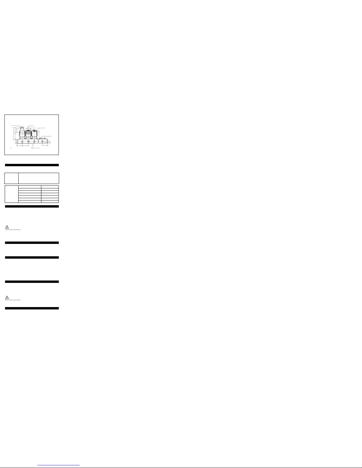
Mounting (Fig 7)
1 The solenoid valve may be mounted in any orientation. However
when mounted upside down, foreign material in the fluid is liable
to adhere to the iron core.This mounting position is not recommended by SMC.
2 Do not keep coil assemblies warm with insulating materials etc. It
will cause the coil to burn out.
Anti-freezing tape, heater etc. should be applied to piping and
body areas only.
3 Except in the case of steel pipes and couplings, mount the valve
with a bracket, especially in the case of non-leak and vacuum
valves.The bracket will help prevent loosening of the couplings.
4 Do not place the valve in areas of severe vibration.
In the case of manifold mounted type valves (where 00 connection
option appears in the part number), see Fig 7.
Ensure that 'O' rings item 5 in Fig 8 are not damaged and free from
any foreign bodies. Locate valve on manifold, being sure to connect
the OUT port on the manifold with the centre port on the valve.Locate
the 4 off mounting screws and tighten so as to achieve an air tight
seal between the valve and the manifold.
049A/ENG
Installation
WARNING
Ensure all air and power supplies are ISOLATED before commencing
installation.
Do not install these valves in explosive atmospheres.
If these valves are exposed to water or oil droplets ensure that they
are protected.
If it is intended to energise a valve for an extended period please consult SMC.
If air leakage causes associated equipment to malfunction cease using
valve and inspect for cause.
Check fixings while pressure and power are applied. Initial function
and leakage tests should be performed after installation.
Install only once safety instructions have been read and understood.
OUT
Symbol
IN
Fig 1 Fig 4
Fig 8
Fig 2
Fig 3
Fig 5
Fig 6
Energise to open type (N.C.) (Fig 1)
Energise to close type (N.O.) (Fig 2)
Type/Valve specifications (Energised close type)
Flow rate Max. operating pressure Max
Orifice differential MPa (kgf/cm
2
) system Proof Weight
Port size Effective Model pressure pressure (g)
size (mmø) Cv area Water Air Oil Steam MPa MPa (Note)
(mm2) (kgf/cm2) (kgf/cm2)
1
/
8
2 0.17 3 VX2112-01 0.9{9} 1.5{15} 0.8{8} 1.0{10}
(6A)
3 0.33 6 VX2122-01 0.45{4.5} 0.7{7} 0.45{4.5} 0.7{7}
4.5 0.61 11 VX2132-01 0.2{2} 0.3{3} 0.2{2} 0.3{3} 280
2 0.17 3 VX2112-02 0.9{9} 1.5{15} 0.8{8} 1.0{10}
VX2122-02 0.45{4.5} 0.7{7} 0.45{4.5} 0.7{7}
3 0.33 6 VX2222-02 0.8{8} 1.0{10} 0.7{7} 1.0{10} 440
1
/
4
VX2322-02 1.2{12} 1.6{16} 1.0{10} - 580
(8A)
VX2132-02 0.2{2} 0.3{3} 0.2{2} 0.3{3} Water 280
4.5 0.61 11 VX2232-02 0.3{3} 0.45{4.5} 0.3{3} 0.45{4.5} Oil 5.0{50} 440
VX2332-02 0.6{6} 0.8{8} 0.6{6} 0.8{8} Air 580
6 1.05 19 VX2242-02 0.15{1.5} 0.25{2.5} 0.15{1.5} 0.25{2.5} 3.0 440
VX2342-02 0.35{3.5} 0.45{4.5} 0.35{3.5} 0.45{4.5} {30} 580
3 0.33 6 VX2222-03 0.8{8} 1.0{10} 0.7{7} 1.0{10} Steam 440
VX2322-03 1.2{12} 1.6{16} 1.0{10} - 1.0{10} 580
3
/
8
4.5 0.61 11 VX2232-03 0.3{3} 0.45{4.5} 0.3{3} 0.45{4.5} 440
(10A) VX2332-03 0.6{6} 0.8{8} 0.6{6} 0.8{8} 580
6 1.05 19 VX2242-03 0.15{1.5} 0.25{2.5} 0.15{1.5} 0.25{2.5} 440
VX2342-03 0.35{3.5} 0.45{4.5} 0.35{3.5} 0.45{4.5} 580
Note: It is a grommet value.Add the conduit 10g, the DIN connector 30g and the terminal 60g respectively.
OUT
Symbol
IN
Symbol
Common pressure type
Individual pressure type
Port A
Port A
Port A
Port P
OUT OUT
OUT
OUT
IN
IN
IN IN
Port P
Port P
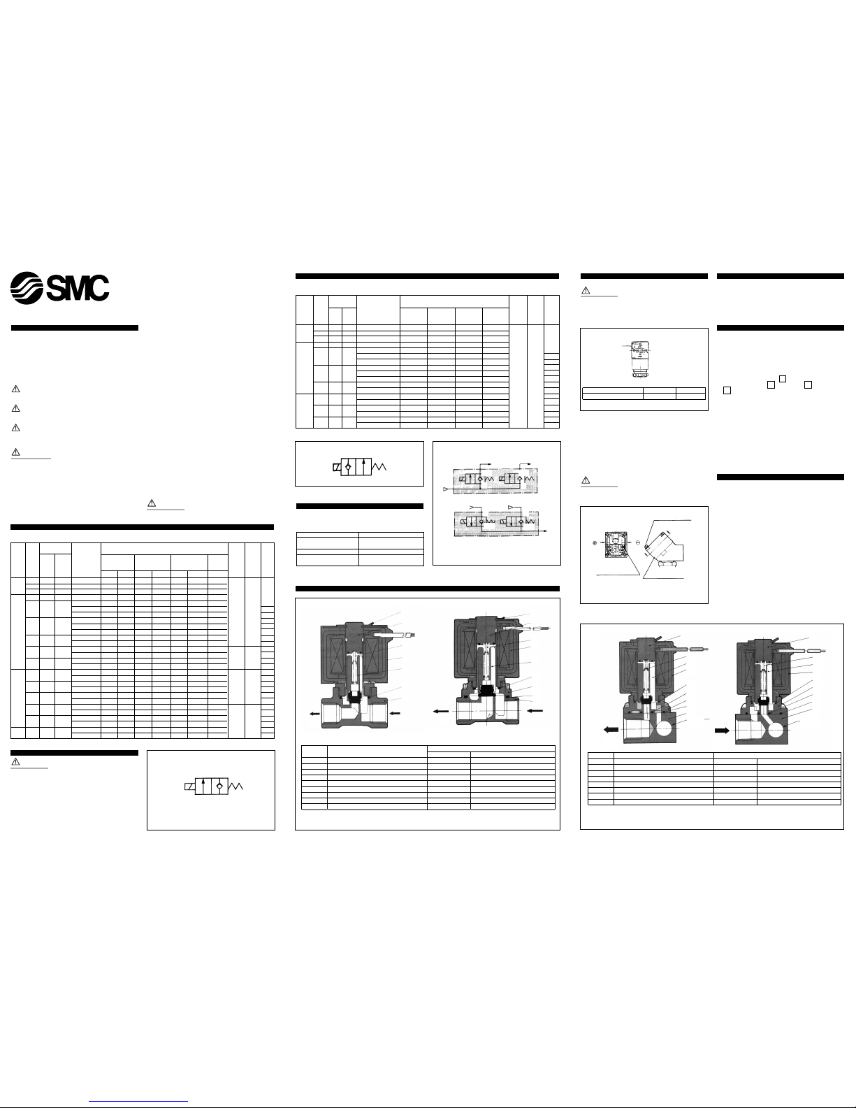
Construction and parts (Fig 4)
7
7
2
4
5
2
4
5
3
3
6
6
8
9
1
1
IN
IN
OUT
P
2
P
1
OUT
VX21/22/23 (Orifice size 2,3,4,5,6mmø) VX22/23 (Orifice size 8,10mmø)
No. Description
Material
Standard Option
1 Body Brass SUS304
2 Core assembly SUS430·Copper SUS430·Silver
3 Armature assembly SUS430·NBR SUS430·FPM/SUS430·PTFE/SUS430·EPR
4 Return spring SUS304 -
5 Coil assembly Class B molded Class H molded
6 O-ring NBR FPM/EPR/PTFE
7 Retainer SUS304 -
8 Bonnet Brass SUS304
9 O-ring NBR FPM/EPR/PTFE
1:+
2:-
Terminal No. 1 2
DIN connector + -
With DIN connector
mark mark
Conduit terminal
Phillips/ordinary
round head screw
M3
Phillips/ordinary
round head screw
M3
View A-A'
(Internal connection)
IN
P
A
R
No. Description Material
Standard Option
1 Body Aluminum -
2 Core assembly SUS430·Copper SUS430·Silver
3 Base Aluminum -
4 Armature assembly SUS430·NBR SUS430·FPM/SUS430·EPR
5 O-ring NBR FPM/EPR
6 Coil assembly Class B molded Class H molded
7 Return spring SUS304 -
Common pressure type Individual pressure type
OUT
Port A
OUT
Port A
IN
Port P
IN
Port P
2
2
7
4
6
5
5
1
5
3
7
4
6
5
1
5
5
3
VX21/22/23
Applicable fluids
VX21/22/23, 2 Port solenoid valves
Standard Water (standard, up to 60°C), air (standard, dry),
turbine oil, spindle oil, Kerosene,vacuum (up to 1
torr), carbon dioxide (CO
2
), nitrogen gas (n2),
Freon 11, 113,114
Fluid Option symbol
Steam (S,Q)
Vacuum (up to 10-3torr) (V,M)
Option Non-leak
(10-5atm cc/sec or less)
(V,M)
High temperature water (X,E,N,P)
High temperature oil (D,N)
Others
VVX21/22/23 Manifold series
Generally, the recommended viscosity of fluid is 50 cSt max. Fluids
contaminated with foreign material can promote wear of the valve
seat and iron core.To prevent this, place a filter/strainer immediately
before the valve.A mesh of 80-100 micron is recommended.
SMC valves are designed for use without lubricant. However,correctly
lubricated air will increase the life of the valve.
CAUTION
These valves are NOT EXPLOSION PROOF.When using inflammable oil
or gas, ensure that there is no leakage either inside or outside of the
valve.
Fluid temperature
Refer to the temperature range for each model.The temperature range
changes according to the sealing material, coil insulation, power
supply,etc.
Ambient conditions
Freezing.When using water in cold environments anti-freeze precautions should be taken.These include but are not limited to, draining of
pumps and valves.When using a heater, avoid applying it to the coil.
Freezing will result when the dew point of the medium is high and the
ambient temperature is low or when a large volume of fluid flows
within the valve. In such cases install a dryer, keep the valve body
warm, or take other preventative measures.
Long period energisation or de-energisation
The valve energisation period depends on the type and viscosity of the
fluid. When pure water is the medium, then the valve should be
switched at least every 10 days.If the period is longer than 10 days, a
system check mechanism should be implemented.
CAUTION
These valves are not intended for use as emergency system valves.
Vibration
These valves should not be subjected to more than 3G and in the case
of non-leak type no more than 1G.
Fig 7
n-
1
/
8
•
1
/
4
(OUT Port)
H
(Pitch)
F F
E
T
W
D
(44)
34.5
DIN connector
Terminal
Conduit
Grommet
Blanking plate
When you enquire about the product, please contact the following
SMC Corporation:
ENGLAND Phone 01908-563888 TURKEY Phone 212-2211512
ITALY Phone 02-92711 GERMANY Phone 6103-402-0
HOLLAND Phone 020-5318888 FRANCE Phone 01-64-76-10-00
SWITZERLAND
Phone 052-34-0022 SWEDEN Phone 08-603 07 00
SPAIN Phone 945-184100 AUSTRIA Phone 02262-62-280
Phone 902-255255 IRELAND Phone 01-4501822
GREECE Phone 01-3426076 DENMARK Phone 8738-0800
FINLAND Phone 09-68 10 21 NORWAY Phone 67-12 90 20
BELGIUM Phone 03-3551464 POLAND Phone 48-22-6131847
 Loading...