

SMC Networks VV100 Series Installation And Maintenance Manual
Installation and Maintenance Manual
Connector type manifold
Series VV100
1 Safety Instructions
• This manual contains essential information for the protection of users
and others from possible injury and/or equipment damage.
• Read this manual before using the product, to ensure correct
handling, and read the manuals of related apparatus before use.
• Keep this manual in a safe place for future reference.
• These instructions indicate the level of potential hazard by label of
"DANGER", "WARNING" or "CAUTION", followed by important safety
information which must be carefully followed.
• To ensure safety of personnel and equipment the safety instructions in
this manual and the product catalogue must be observed, along with
other relevant safety practices.
VV100**-TFL0002
WARNING
• The compatibility of pneumatic equipment is the responsibility of
the person who designs the pneumatic system or decides its
specifications.
Since the products specified here can be used in various operating
conditions, their compatibility with the specific pneumatic system must
be based on specifications or after analysis and/or tests to meet
specific requirements.
• Only trained personnel should operate pneumatically operated
machinery and equipment.
Compressed air can be dangerous if an operator is unfamiliar with it.
Assembly, handling or repair of pneumatic systems should be
performed by trained and experienced personnel.
• Do not service machinery/equipment or attempt to remove
components until safety is confirmed.
1) Inspection and maintenance of machinery/equipment should only
be performed after confirmation of safe locked-out control positions.
2) When equipment is to be removed, confirm the safety process as
mentioned above. Switch off air and electrical supplies and exhaust all
residual compressed air in the system.
3) Before machinery/equipment is re-started, ensure all safety
measures to prevent sudden movement of cylinders etc. (Supply air
into the system gradually to create back pressure, i.e. incorporate a
soft-start valve).
• Do not use this product outside of the specifications.
Contact SMC if it is to be used in any of the following conditions:
1) Conditions and environments beyond the given specifications, or if
the product is to be used outdoors.
2) Installations in conjunction with atomic energy, railway, air
navigation, vehicles, medical equipment, food and beverage, recreation
equipment, emergency stop circuits, press applications, or safety
equipment.
3) An application which has the possibility of having negative effects on
people, property, or animals, requiring special safety analysis.
CAUTION
• Ensure that the air supply system is filtered to 5 microns.
1 Safety Instructions
(continued)
Exemption from Liability.
1) SMC, its officers and employees shall be exempt from liability for any
loss or damage arising out of earthquake or fire, action by a third person,
accidents, customer error with or without intention, product misuse and
any other damages caused by abnormal operating conditions.
2) SMC, its officers, and its employees shall be exempt from liability for
any incidental damage that is caused by the use or the inability to use this
product (loss of business interests, business interruptions, etc)
3) SMC is exempt from liability for any damages caused by operations not
contained in the catalogs and/or instruction manuals, and operations
outside of the specification range.
4) SMC is exempt from liability for any loss or damage whatsoever caused
by malfunctions of its products when combined with other devices or
software.
2 Specifications
2.1 Valve specifications
Note :
Impact resistance: No malfunction occurred when it was tested with a drop
tester in the axial direction and at right angles to the main valve & armature;
in both energized & de-energised states and for every time in each condition
(Values at the initial period.)
Vibration resistance: No malfunction occurred in a one-sweep test between
45 and 2000 Hz. Tests ere performed at both energized and de-energized
states in the axial direction and at right angles to the main valve & armature.
(Valves at the initial period.)
2.2 Coil specifications
Note) Keep the following voltage range for Z type and T type (with power
saving circuit) because it might have voltage drop due to internal circuit.
Z type T type
24VDC : -7 ~ +10% 24VDC : -5 ~ +10%
12VDC : -6 ~ +10% 12VDC : -6 ~ +10%
2.3 Symbol
3 Installation
3.1 Installation
WARNING
• Do not install the product unless the safety instructions have been read
and understood.
• Interlock circuit
If the products are used in an interlock circuit, prepare a double interlock
style circuit with a mechanical protection function for the prevention of a
breakdown. Examine these.
3.2 Environment
WARNING
• Do not use in an environment where the product is directly exposed to
corrosive gases, chemicals, salt water, water or steam.
• Do not use in an explosive atmosphere.
• The product should not be exposed to prolonged sunlight.Use a protective
cover.
• Do not mount the product in a location where it is subject to strong
vibrations and/or shock. Check the product specifications.
• Do not mount the product in a location exposed to radiant heat.
If using in an atmosphere where there is possible contact with water droplets, oil, weld spatter, etc., take suitable preventative measures.
• When the solenoid valve is mounted in a control panel or its energized for
a long time, make sure that the ambient temperature is within the valve's
specified range
3.3 Piping
CAUTION
• Before piping make sure to clean up chips, cutting oil, dust etc.
• When installing piping or fittings, ensure sealant material does not enter
inside the port. When using seal tape, leave 1.5 to 2 threads exposed on
the end of the pipe/fitting.
• Tighten fittings according to appropriate tightening torque.
3.4 One-touch fitting
CAUTION
Tube attachment
• Take a tube having no flaws on its periphery and cut it off at a right angle.
When cutting the tube, use tube cutters TK-1, 2 or 3. Do not use pincers,
nippers or scissors etc. If cutting is done with tools other than tube cutters,
the tube may be cut diagonally or become flattened. This makes a secure
installation impossible, and causes problems such as air leakage or the
tube being pulled out after installation. Allow some extra length in the tube.
Hold down part of the release bush
with your finger or a similar tool, as
shown in the diagram, and pull out in
the direction indicated by the arrow.
• Grasp the tube and push it in slowly, inserting it securely all the way into
the fitting.
• After inserting the tube, pull on it lightly to confirm that it will not come out.
Problems such as air leakage or the tube being pulled out can occur if the
tube is not inserted securely all the way into the fittings.
Tube detachment
• Push in the release bushing and the collar at the same time.
• Pull out the tube while holding down the release bushing so that it does not
come out. If the release bushing is not pressed down sufficiently there will
be increased bite on the tube and it will become more difficult to pull out.
• When the removed tube is to be used again, cut off the portion which has
been chewed before reusing it. If this is not done then the chewed portion
of the tube can cause problems such as air leakage or difficulty in
removing the tube from the fitting.
3 Installation
(continued)
3.5 Precautions on other tube brands
CAUTION
• When using non-SMC brand tubes, confirm that the following
specifications are satisfied with respect to the outside diameter
tolerance of the tube.
Nylon tube ±0.1mm
Soft nylon tube ±0.1mm
Polyurethane tube +0.15mm
-0.2mm
x Do not use tubes that do not meet these outside diameter tolerances. It
may not be possible to connect them, or they may cause other
problems, such as air leakage or the tube pulling out after connection.
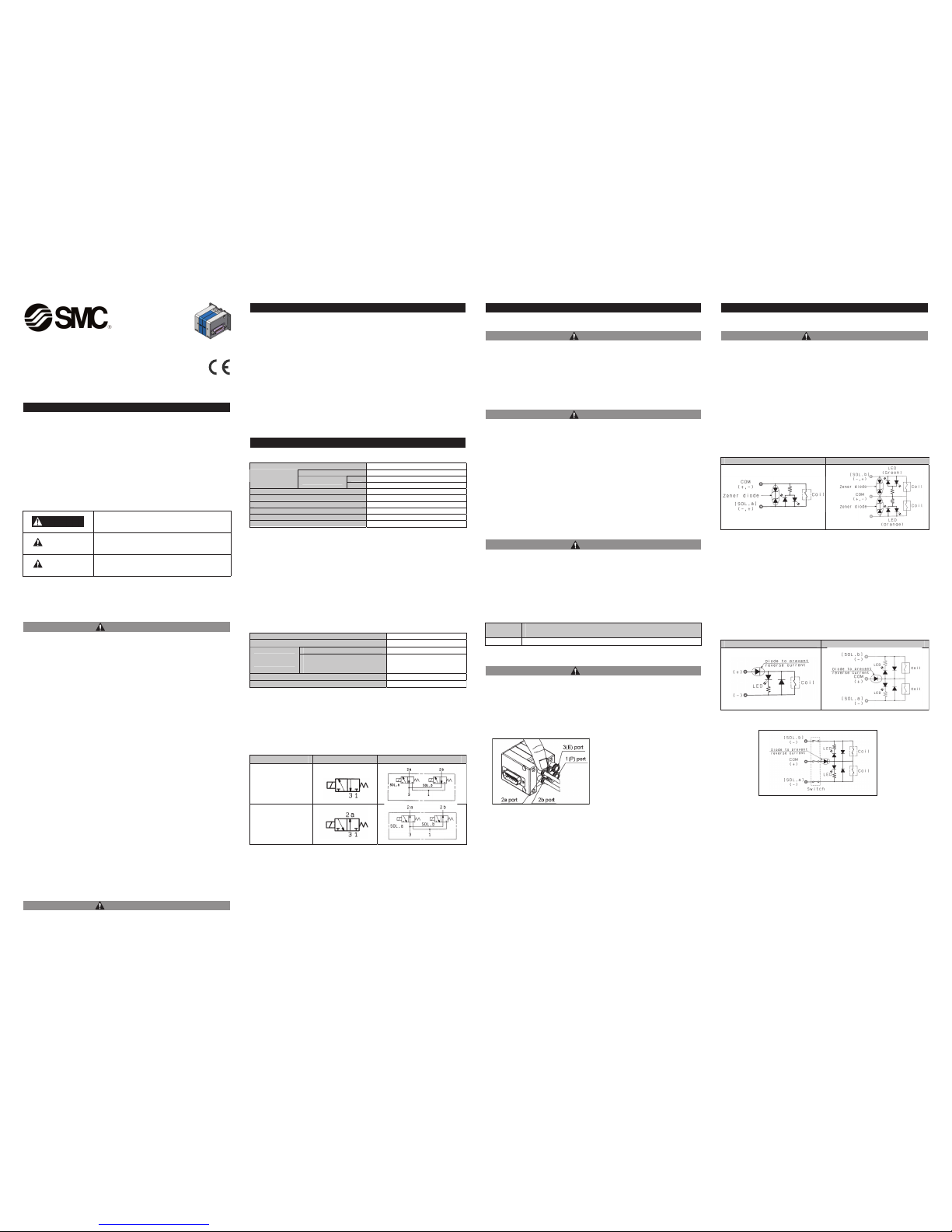
3.6 Indicator Light/Surge Voltage Suppressor
• Non-polar type
When the solenoid valve has no polarity:
In extreme conditions, there is a possibility of
serious injury or loss of life.
WARNING
If instructions are not followed there is a
possibility of serious injury or loss of life.
CAUTION
If instructions are not followed there is a
possibility of injury or equipment damage.
DANGER
Fluid
Air
Positive pressure
0 ~ 0.7MPa
N.C.
1port :-100kPa~0.6 / 3port :100kPa~0
Operating
pressure range
MPa
Vacuum pressure
N.O.
1port :-100kPa~0 / 3port :100kPa~0.6
Ambient and fluid temperature °C
Max.50
Maximum operating frequency Hz
20
Lubrication
Non required
Mounting position
Unrestricted
Impact / Vibration resistance m/s
2
150/30 *Note)
Protection structure
IP40
CDV21,42 )etoN* egatlov detaR
Allowable voltage fluctuation
±10% rated voltage
4.0 dradnatS
Power
Consumption W
Power saving type
(Extended periods
continuously energized)
0.15
edoiD rosserppus egatlov egruS
DEL thgil rotacidnI
Type of actuation Single Double
N.C.
N.O.
2a
Thread
Appropriate tightening
torque N•m
2 ot 5.1 5M
Single solenoid Double solenoid
• Polar type
When the solenoid valve has polarity:
• With switch
• Extended periods of continuous energisation
• Continuous energisation of the valve for extended periods of time may
have an adverse effect on the solenoid valve performance and the
peripheral equipment. This is due to temperature rises caused by the
heat generated by the coil.
Consult with SMC if a valve will be continuously energised for extended
periods of time or if the energized period per day will be longer than the
de-energized period. It is also possible to shorten the energisation
period by using valves of the N.O.(normally open) type.
• When solenoid valves are mounted in a control panel, employ
measures to radiate away excess heat, so that temperatures remain
within the valve specification range.Be particular ly aware when three or
more stations that are sequentially aligned on the manifold are
continuously energized. This will cause a drastic temperature rise.
Single solenoid Double solenoid
3 Installation
(continued)
3.7 Light Indication
CAUTION
When equipped with indicator light and surge voltage suppressor, the light
window turns orange when solenoid A is energized, and green when
solenoid B is energized.
VV100**-TFL0002
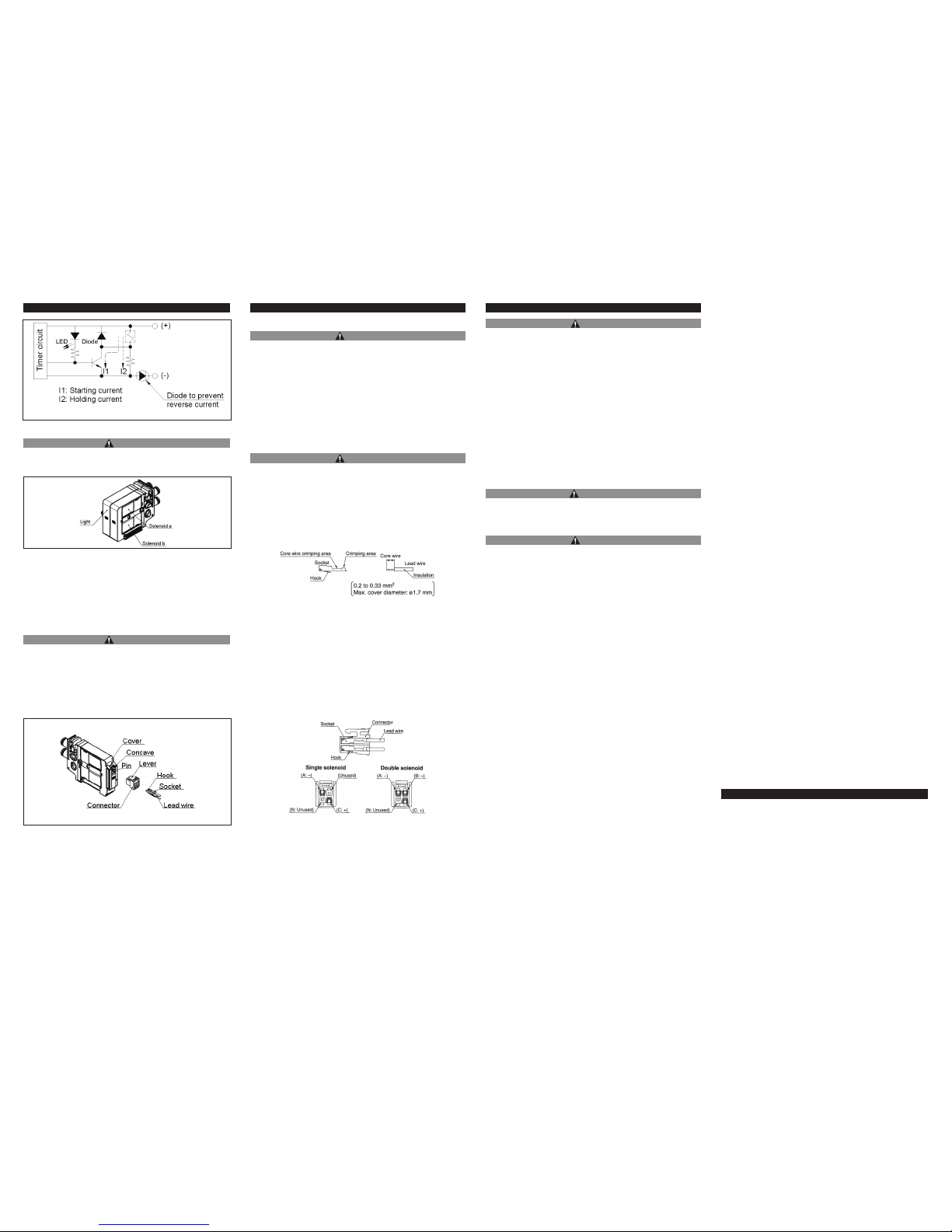
3.8 How to Use Plug Connector
CAUTION
When attaching and detaching a connector, first shut off the electric power
and the air supply.Also, crimp the lead wires and sockets securely.
Attaching and detaching connectors
• To attach a connector, hold the lever and connector unit between your
fingers and insert straight onto the pins of the solenoid valve so that the
lever's pawl is pushed into the groove and locks.
• To detach a connector, remove the pawl from the groove by pushing the
lever downward with your thumb, and pull the connector straight out.
4 Maintenance
4.1 General Maintenance
CAUTION
• Not following proper maintenance procedures could cause the product to
malfunction and lead to equipment damage.
• If handled improperly, compressed air can be dangerous.Maintenance of
pneumatic systems should be performed by qualified personnel only.
• Before performing maintenance ensure the supply pressure is shut off and
all residual air pressure is released from the system.
• After maintenance apply operating pressure and power to the equipment
and check for proper operation and possible air leaks. If operation is
abnormal, verify product set-up parameters.
• Do not make any modification to the product.
• Do not disassemble the product, unless required by installation or
maintenance instructions.
4.2 Fitting Assembly Replacement
CAUTION
By replacing a valve's fitting assembly, it is possible to change the port size
of the 2a, 2b, 1(P), and 3(E) ports. When replacing it, pull out the fitting
assembly after removing the clip with a flat head screwdriver, etc.To mount
a new fitting assembly, insert it into place and then fully reinsert the clip.
• Crimping or lead wires and sockets
Peel 3.2 to 3.7mm of the tip of lead wire, enter the core wires neatly into a
socket and crimp it with a special crimp tool. Be careful so that the cover
of lead wire does not enter into the crimping part.
(Crimping tool: Model no. DXT170-75-1).
Attaching and detaching lead wires with sockets
• Attaching
Insert the sockets into the square holes of the connector (with A,B,C and
N indication), and continue to push the sockets all the way in until the lock
by hooking into the seats in the connector.(When they are pushed in, their
hooks open and they are locked automatically.) Next, confirm that they are
locked by pulling lightly on the lead wires.
• Detaching
To detach a socket from a connector, pull out the lead wire while pressing
the socket's hook with a stick having a thin tip (approx.1mm). If the socket
is used again, spread the hook outward.
5 Limitations of Use
CAUTION
• Leakage voltage
The suppressor residual voltage should be 3 % or less of the rated voltage.
• Surge voltage suppressor
If a surge protection circuit contains non-ordinary diodes such as zener
diodes or varistor, a residual voltage will remain that is in proportion to the
protective elements & the rated voltage. Therefore, give consideration to
surge voltage protection of the controller.In the case of diodes, the residual
voltage is approximately 1 V.
• Low temperature operation
Unless otherwise indicated in the specifications for each valve, operation
is possible to -10°C, but appropriate measures should be taken to avoid
solidification or freezing of drainage and moisture, etc.
• Mounting orientation
Mounting orientation is universal.
• Low frequency operation
Valves should be operated at least once every 30 days to prevent
malfunction. (Use caution regarding the air supply.)
5.1 Supply air
WARNING
• Use clean air
If the compressed air supply includes chemicals, synthetic materials
(including organic solvents), salinity, corrosive gas etc., it can lead to
damage or malfunction.
CAUTION
• Install an air filter
Install an air filter at the upper streamside of the valve. Filtration degree
should be 5µm or less.
5.2 Limited warranty and disclaimer/compliance requirements
The product used is subject to the following "Limited warranty and
Disclaimer" and "Compliance Requirements". Read and accept them before
using the product.
Limited warranty and Disclaimer
1) The warranty period of the product is 1 year in service or 1.5 years after
the product is delivered.
*3)
Also, the product may have specified durability, running distance or
replacement parts. Please consult your nearest sales branch.
2) For any failure or damage reported within the warranty period which is
clearly our responsibility, a replacement product or necessary parts will be
provided.
This limited warranty applies only to our product independently, and not to
any other damage incurred due to the failure of the product.
3) Prior to using SMC products, please read and understand the warranty
terms and disclaimers noted in the specified catalog for the particular
products.
*3) Vacuum pads are excluded from this 1 year warranty.
A vacuum pad is a consumable part, so it is warranted for a year after it is
delivered.
Also, even within the warranty period, the wear of a product due to the use
of the vacuum pad or failure due to the deterioration of rubber material are
not covered by the limited warranty.
5.3 Compliance Requirements
When the product is exported, strictly follow the laws required by the Ministry
of Economy, Trade and Industry (Foreign Exchange and Foreign Trade
Control Law.
6 Contacts
SMC Corporation www.smcworld.com (Global) www.smceu.com (Europe)
Specifications are subject to change without prior notice from the manufacturer.
The descriptions of products in this document may be used by other companies.
© SMC Corporation All Rights Reserved.
AUSTRIA (43) 2262-62 280 NETHERLANDS (31) 20-531 8888
BELGIUM (32) 3-355 1464 NORWAY (47) 67 12 90 20
CZECH REP. (420) 5-414 24611 POLAND (48) 22 211 9600
DENMARK (45) 70 25 29 00 PORTUGAL (351) 21 471 1880
FINLAND (358) 207 513513 SLOVAKIA (421) 2 444 56725
FRANCE (33) 1-64 76 1000 SLOVENIA (386) 73 885 412
GERMANY (49) 6103 4020 SPAIN (34) 945-18 4100
GREECE (30) 210 271 7265 SWEDEN (46) 8-603 0700
HUNGARY (36) 1-371 1343 SWITZERLAND (41) 52-396 3131
IRELAND (353) 1-403 9000 UNITED KINGDOM (44) 1908-56 3888
ITALY (39) 02-92711
 Loading...