

SMC Networks VR51 Installation And Maintenance Manual
VR51-TFO26-A
Installation and Maintenance Manual
Original Instructions
VR51, Two Hand Control Valve
1 Safety Instructions
This manual contains essential information for the protection of users and
others from possible injury and/or equipment damage.
• Read this manual before using the product, to ensure correct
handling, and read the manuals of related apparatus before use.
• Keep this manual in a safe place for future reference.
• These instructions indicate the level of potential hazard by label of
“Caution”, “Warning” or “Danger”, followed by important safety
information which must be carefully followed.
• To ensure safety of personnel and equipment the safety instructions
in this manual and the product catalogue must be observed, along
with other relevant safety practices.
Caution
Indicates a hazard with a low level of risk, which if not
avoided, could result in minor or moderate injury.
Warning
Indicates a hazard with a medium level of risk, which
if not avoided, could result in death or serious injury.
Danger
Indicates a hazard with a high level of risk, which if
not avoided, will result in death or serious injury.
Warning
• The compatibility of pneumatic equipment is the responsibility of the
person who designs the pneumatic system or decides its
specifications.
Since the products specified here can be used in various operating
conditions, their compatibility with the specific pneumatic system must
be based on specifications or after analysis and/or tests to meet
specific requirements.
• Only trained personnel should operate pneumatically operated
machinery and equipment.
Compressed air can be dangerous if an operator is unfamiliar with it.
Assembly, handling or repair of pneumatic systems should be
performed by trained and experienced personnel.
• Do not service machinery/equipment or attempt to remove
components until safety is confirmed.
1) Inspection and maintenance of machinery/equipment should only
be performed after confirmation of safe locked-out control positions.
2) When equipment is to be removed, confirm the safety process as
mentioned above. Switch off air and electrical supplies and exhaust
all residual compressed air in the system.
3) Before machinery/equipment is re-started, ensure all safety
measures to prevent sudden movement of cylinders etc. (Supply air
into the system gradually to create back pressure, i.e. incorporate a
soft-start valve).
• Do not use this product outside of the specifications. Contact
SMC if it is to be used in any of the following conditions:
1) Conditions and environments beyond the given specifications, or if
the product is to be used outdoors.
2) Installations in conjunction with atomic energy, railway, air
navigation, vehicles, medical equipment, food and beverage,
recreation equipment, emergency stop circuits, press applications, or
safety equipment.
3) An application which has the possibility of having negative effects
on people, property, or animals, requiring special safety analysis.
Caution
• Ensure that the air supply system is filtered to 5 μm.
2 Specifications
2.1 Specifications
Fluid Air
Operating pressure 0.25 to 1.0 MPa
Proof pressure 1.5 MPa
Ambient and fluid temperature -5 to 60°C (with no freezing)
Flow characteristics C[dm3/(s·bar)] b Cv
Operating frequency Max 10cpm
Operating frequency Min Once every 30 days
Vibration & shock resistance Do not use in a vibration environment
Environment Indoor use only
P to A 0.3 - A to R 1.0 0.12 0.25
Metric Ø6 Port size
Inch Ø1/4
Applicable tube material Note) Nylon, Soft nylon, Polyurethane,
Flame resistant (FR) soft nylon,
FR double layer,
FR double layer polyurethane
Weight 340g
Silencer Part No.: AN101-01 Accessory
option
Bracket Part No.: VR51B
Note) In the case of soft nylon or polyurethane tubing, use caution when
the maximum operating pressure of the tubing is used.
2.2 Features
• When there is a time delay of less than 0.5 seconds between the two
air signal inputs, the VR51 provides an output signal.
• VR51 output stops when one of the two air signal inputs stops.
• Two simultaneous air signals resets the output.
2.3 Declaration of Conformity
A sample Declaration of conformity (DoC) for this product is shown below.
An actual DoC is supplied with each product.
2 Specifications (Continued)
2.4 Typical Circuit
2.5 Production batch code
The production batch code printed on the label indicates the month and
year of production as shown in the following table:
Production batch codes
2010 2011 2012 … 2021 2022 2023 …
Year
Month
H I J … Z A B …
Jan O oo Po Qo … Zo Ao Bo …
Feb P oP PP QP … ZP AP BP …
Mar Q oQ PQ QQ … ZQ AQ BQ …
Apr R oR PR QR … ZR AR BR …
May S oS PS QS … ZS AS BS …
Jun T oT PT QT … ZT AT BT …
Jul U oU PU QU … ZU AU BU …
Aug V oV PV QV … ZV AV BV …
Sep W oW PW QW … ZW AW BW …
Oct X oX PX QX … ZX AX BX …
Nov Y oy Py Qy … Zy Ay By …
Dec Z oZ PZ JZ … ZZ AZ BZ …
Note that lowercase letters are used in some instances.
3 Installation
3.1 Installation
Warning
• Do not install the product unless the safety instructions have been
read and understood.
Note) Order the silencer separately, see section 2.
3 Installation (Continued)
3.1 Environment
Warning
• Do not use in an environment where corrosive gases, chemicals, salt
water or steam are present.
• Do not use in an explosive atmosphere.
• Do not expose to direct sunlight. Use a suitable protective cover.
• Do not install in a location subject to vibration or impact. Check the
product specifications.
• Do not mount in a location exposed to radiant heat.
• Employ suitable protective measures in locations where there is
contact with oil or welding spatter etc.
Caution
• Avoid using in places where there is splashing oil, coolant or water.
In addition, avoid using where dust may adhere.
3.2 Piping
Warning
• Before piping make sure to clean up chips, cutting oil, dust etc.
• When connecting piping, consult the instruction manual and use
caution to avoid incorrect piping.
• Connect tubing with a longer length than required to prevent torsion,
stretching or moment loads. Damage of the fittings or flattening, as
well as bursting or releasing of the tubing may occur if the instructions
are not followed.
• Tubing connected to the VR51 should be used at more than its
minimum bend radius. If used under the minimum bend radius,
bending or flattening of the tubing may occur.
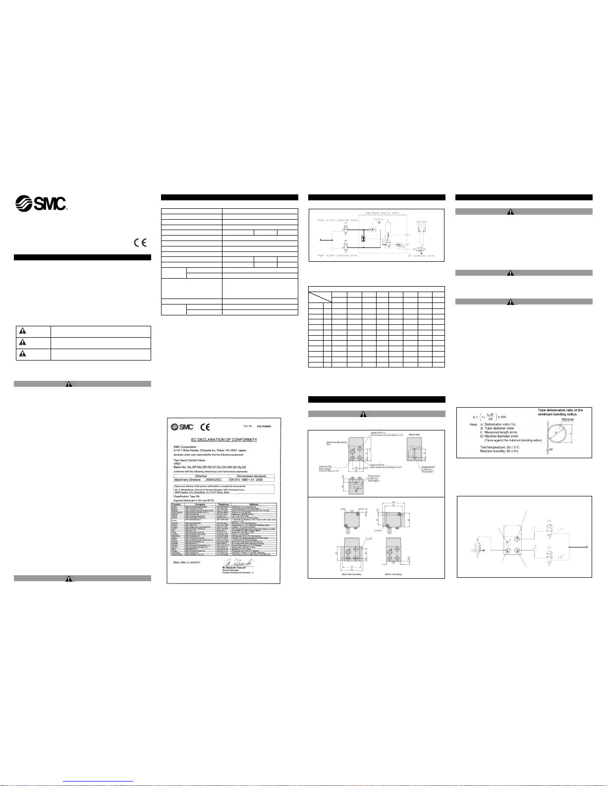
The minimum bend radius is measured in accordance with JIS B
8381-1995.
JIS specifies the tubing deformation ratio measured at the
minimum bend ratio to be 25% or less.
*Except for the TU, TIUB, TUH, TRBU, TAU and TUS series
Tube deformation ratio at the minimum bend radius is obtained by the following formula, based on
tube and mandrel diameter
• Use the same control valves for each input port.
• Use tubing of the same length and diameter between the VR51 and
each control actuating device: L2=L1, L2’=L1’.
• Operate the control valves from the same pressure source.
3.3 Piping Length for Secondary Side
Bracket mounting dimensions
EXHAUST PORT:R(4)
OUTPUT PORT:A(2)
SUPPLY PORT:P2(12)
SUPPLY PORT:P1(11)
Output Port: A(2)
Supply Port: P2(12)
Exhaust Port: R(4)
Supply Port: P1(11)
VR51-TFO26-A
3 Installation (Continued)
When the outlet side piping length is long or the piping capacity is large
due to a branch, output from the A port may not occur when the operation
buttons are pressed simultaneously because the outlet pressure will rise
slowly.
The applicable piping capacity for the outlet side is calculated by the tubing
length of T0604 (I.D. ø4 mm). The outlet side piping length should be less
than the values shown in the graph below.
When the piping length is long or the capacity is large due to a branch,
install a speed controller (AS2051F-06, AS3001F-06, etc.) close to the A
port as shown in the figure below.
3.1 Lubrication
Caution
• SMC products have been lubricated for life at manufacture, and do
not require lubrication in service.
• If a lubricant is used in the system, use turbine oil Class 1 (no
additive), ISO VG32. Once lubricant is used in the system, lubrication
must be continued because the original lubricant applied during
manufacturing will be washed away.
4 Operation Timing and Output
4.1 Control timing
VR51 provides an output signal when there is less than 0.5 seconds
difference between the two input air signals, see timing diagram below.
The output delay* depends on the piping arrangement and the operating
pressure. The relationship between output timing delay and pressure is
given in the chart. This is for typical piping, the exact delay will depend on
the application.
4 Operation Timing and Output (continued)
Output timing delay
5 Operating Button Setup
5.1 Preparing the b uttons for use
Caution
Design and prepare the buttons in accordance with instruction manuals
and European Directives. Install the button according to EN 574 Safety of
machinery. Two-hand control devices. Functional aspects. Principles for
design
If the operating buttons are incorrectly arranged, an unexpected motion is
likely to occur and safety cannot be maintained.
Principle precautions:
• Configure the buttons so only 2 hand operation is possible, ensure it
is not possible to operate by 1 hand only.
• Configure the buttons so only 2 hand operation is possible, as to
ensure it is not possible to operate by forearm(s) or elbow(s).
• Configure the buttons so only 2 hand operation is possible, as to
ensure it is not possible to operate by 1 hand and any other part of
the body (knee or hip for example).
Example of button setup:
6 Maintenance
6.1 General Maintenance
Caution
• Not following proper maintenance procedures could cause the
product to malfunction and lead to equipment damage.
• If handled improperly, compressed air can be dangerous.
Maintenance of pneumatic systems should be performed only by
qualified personnel.
• Before performing maintenance, turn off the power supply and be
sure to cut off the supply pressure. Confirm that the air is released to
atmosphere.
• After installation and maintenance, apply operating pressure and
power to the equipment and perform appropriate functional and
leakage tests to make sure the equipment is installed correctly.
• Do not make any modification to the product.
• Do not disassemble the product, unless required by installation or
maintenance instructions.
• Low frequency operation: Valves should be switched at least once
every 30 days to prevent malfunction. (Use caution regarding air
supply.)
• Perform a periodical inspection if necessary when first starting the
product to confirm that the two hand control valve is operating without
fail.
7 Air Supply
7.1 Air quality
Warning
• Use clean air.
Do not use compressed air which contains chemicals, synthetic oils
containing organic solvents, salts or corrosive gases, etc., as this can
cause damage or malfunction.
Caution
• Install air filters.
Install air filters close to valves on the upstream side. A filtration
degree of 5 μm or less should be selected.
• Install an air dryer, after cooler or water separator, etc.
Air that includes excessive moisture may cause malfunction of valves
and other pneumatic equipment. To prevent this, install an air dryer,
after-cooler or water separator, etc.
• If excessive carbon dust is present, install a mist separator on the
upstream side of the valve.
If excessive carbon dust is generated by the compressor, it may adhere
to the inside of valves and cause malfunction.
Refer to SMC’s “Air Cleaning Equipment” catalogue for compressed air
quality.
7.2 Pneumatic pressure
Warning
• Do not use fluids other than those specified. The only fluid that can
be used is air.
• Do not use the product with a pressure under 0.25 MPa. The time lag
for operating the VR51 is different depending on the operating
pressure. The higher the operating pressure, the shorter the time lag,
and vice versa. If used under 0.25 MPa, an output will be produced;
however, safety is not likely to be maintained, even though the time
lag may exceed 0.5 seconds.
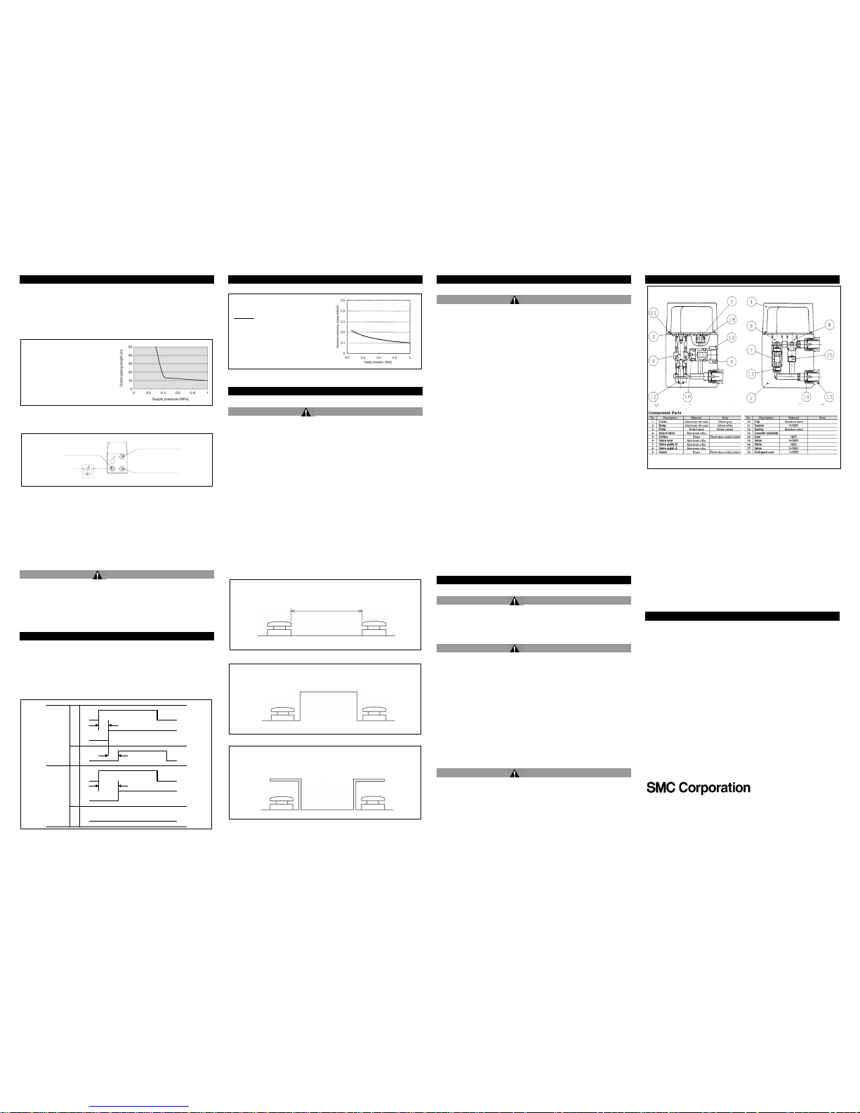
8 Construction
9 Contacts
Europe:
AUSTRIA (43) 2262-62280-0 LATVIA (371) 781 77 00
BELGIUM (32) 3-355-1464 LITHUANIA (370) 5 264 8126
BULGARIA (359) 2 9744492 NETHERLANDS (31) 20 531 8888
CZECH REP. (420) 541-424-611 NORWAY (47) 67 12 90 20
DENMARK (45) 7025 2900 POLAND (48) 22 211 9600
ESTONIA (372) 651 0370 PORTUGAL (351) 21 471 1880
FINLAND (358) 207 513513 ROMANIA (40) 21 320 5111
FRANCE (33) 1-6476-1199 SLOVAKIA (421) 2 444 56725
GERMANY (49) 6103-402-0 SLOVENIA (386) 73 885 412
GREECE (30) 210-2717265 SPAIN (34) 945 184 100
HUNGARY (36) 23-511-390 SWEDEN (46) 8 603 1200
IRELAND (353) 1-403-9000 SWITZERLAND (41) 52 396 3131
ITALY (39) 02 92711 UNITED KINGDOM (44) 1908 563888
Outside Europe:
JAPAN (81) 3-5207-8271 USA (1) 317-899-4440
URL : http// www.smcworld.com (Global) http// www.smceu.com (Europe)
SMC Corporation, Akihabara UDX15F, 4-14-1, Sotokanda, Chiyoda-ku, Tokyo
101-0021 JAPAN
Specifications are subject to change without prior notice from the manufacturer.
© 2012 SMC Corporation All Rights Reserved.
Conditions
1, Piping: Tube: T0604 with I.D. Ø4mm
2, Piping length: Primary side 1m
Secondary side 3m
3, Connected equipment: 1 Air operated valve
Supply pressure and piping
length at the outlet side
Ensure a safe spacing of the buttons so they cannot be operated by 1
hand
Install an isolating object between the buttons so they cannot be
operated by 1 hand
Place a cover over both buttons so they cannot be operated by 1 hand
SUPPLY PORT:P1(11)
SUPPLY PORT:P2(12)
OUTPUT PORT:A(2)
A
Output
No output
< 0.5s
> 0.5s
Output
delay*
P1
P2
A
P1
P2
 Loading...