

SMC Networks VQZ 1000, VQZ2000, VQZ3000 Installation And Maintenance Manual
3.7 Valve mounting
Installation and Maintenance Manual
5 Port Solenoid Valve
Series VQZ 1000/2000/3000
Read this manual before using this product
• The information within this document is to be used by pneumatically trained
personnel only.
• For future reference, please keep manual in a safe place.
• This manual should be read in conjunction with the current catalogue.
1 Safety Instructions
2 Specifications
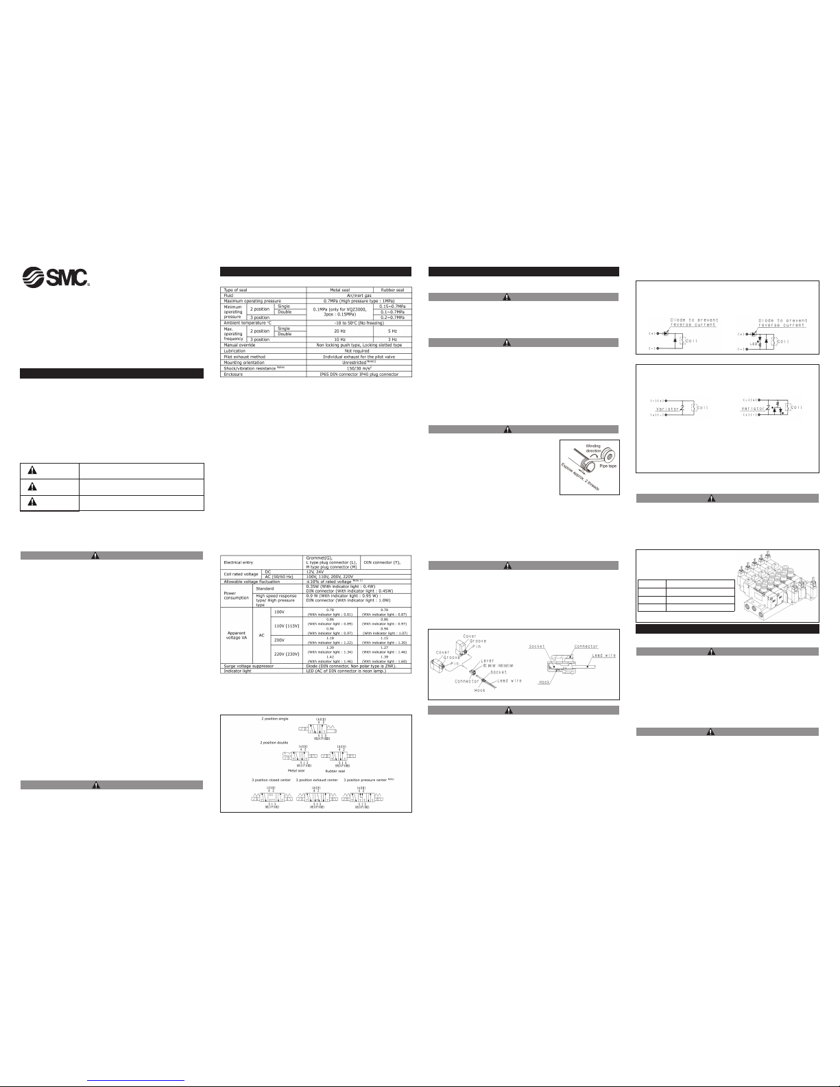
2.1 VQZ1000/2000/3000 Standard Specification
Note 1: Double solenoid type so that a spool becomes level
Note 2: Shock resistance: No malfunction occurred when it was tested with a drop
tester in the axial direction and at right angles to the main valve & armature; in
both energized & de-energised states and for every time in each condition (Values
at the initial period.)
Vibration resistance: No malfunction occurred in a one-sweep test between 45
and 2000 Hz. Test was performed at both energized and de-energized states in
the axial direction and at right angles to the main valve & armature. (Valves at the
initial period.)
Solenoid Specifications
Note 1) In common between 110 VAC and 115 VAC, and between 220 VAC and
230 VAC. For 115 VAC and 230 VAC, the allowable voltage is -15% to
+5% of rated voltage.
Note 2) AC type is applicable to only Y, YO and YZ.
2.2 Circuit symbols
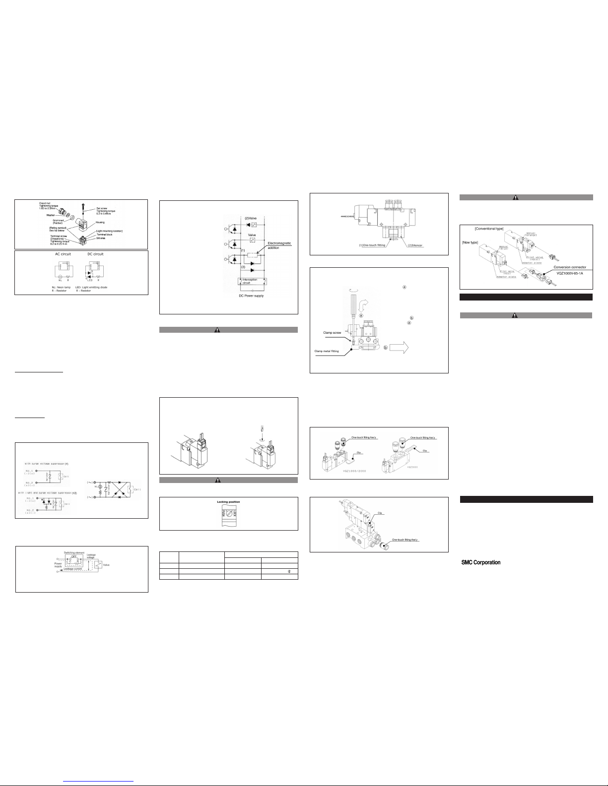
3.5 Electrical connection L/M type plug connector
Insertion/ Removal of Connector
Insertion - Push the connector straight on to the pins of the solenoid, making
sure the lip of the lever securely "locks" into the groove of the solenoid cover.
Removal - Press the lever against the connector housing and pull it away from
the solenoid.
CAUTION
<Non-polar type>
With surge voltage suppressor (R)
With light/surge voltage suppressor (U)
-please correctly connect the lead wires to +(positive) and -(negative) indications
on the connector.
-For DC voltages other then 12,24 incorrect wiring will cause damage to the surge
voltage suppressor circuit. (Wrong polarity will cause trouble).
-Solenoids, whose lead wires have been pre-wired, are positive side red and
negative side black.
In extreme conditions, there is a possibility of serious
injury or loss of life.
If instructions are not followed there is a possibility of
serious injury or loss of life.
If instructions are not followed there is a possibility of
injury or equipment damage.
CAUTION
WARNING
DANGER
• This manual contains essential information for the protection of users and
others from possible injury and/or equipment damage.
• Read this manual before using the product, to ensure correct handling, and
read the manuals of related apparatus before use.
• Keep this manual in a safe place for future reference.
• These instructions indicate the level of potential hazard by label of
"DANGER", "WARNING" or "CAUTION", followed by important safety
information which must be carefully followed.
• To ensure safety ISO4414: Pneumatic fluid power and JIS B 8370:
Pneumatic system axiom must be observed, along with other relevant safety
practices.
• The compatibility of pneumatic equipment is the responsibility of the person
who designs the pneumatic system or decides its
specifications.
Since the products specified here can be used in various operating
conditions, their compatibility with the specific pneumatic system must be
based on specifications or after analysis and/or tests to meet
specific requirements.
• Only trained personnel should operate pneumatically operated
machinery and equipment.
Compressed air can be dangerous if an operator is unfamiliar with it.
Assembly, handling or repair of pneumatic systems should be performed by
trained and experienced personnel.
• Do not service machinery/equipment or attempt to remove
components until safety is confirmed.
1) Inspection and maintenance of machinery/equipment should only be
performed after confirmation of safe locked-out control positions.
2) When equipment is to be removed, confirm the safety process as
mentioned above. Switch off air and electrical supplies and exhaust all
residual compressed air in the system.
3) Before machinery/equipment is re-started, ensure all safety measures to
prevent sudden movement of cylinders etc. (Supply air into the
system gradually to create back pressure, i.e. incorporate a soft-start valve).
• Do not use this product outside of the specifications. Contact SMC if it is to
be used in any of the following conditions:
1) Conditions and environments beyond the given specifications, or if the
product is to be used outdoors.
2) Installations in conjunction with atomic energy, railway, air navigation,
vehicles, medical equipment, food and beverage, recreation equipment,
emergency stop circuits, press applications, or safety equipment.
3) An application which has the possibility of having negative effects on
people, property, or animals, requiring special safety analysis.
• Ensure that the air supply system is filtered to 5 microns.
WARNING
CAUTION
3.2 Environment
3 Installation
WARNING
• Do not use in an environment where the product is directly exposed
to corrosive gases, chemicals, salt water, water or steam.
• Do not use in an explosive atmosphere.
• The product should not be exposed to prolonged sunlight. Use a
protective cover.
• Do not mount the product in a location where it is subject to strong vibrations
and/or shock. Check the product specifications.
• Do not mount the product in a location exposed to radiant heat.
3.3 Piping
CAUTION
• Before piping make sure to clean up chips, cutting
oil, dust etc.
• When installing piping or fittings, ensure sealant
material does not enter inside the port. When using
seal tape, leave 1.5 to 2 threads exposed on the end
of the pipe/fitting.
• Tighten fittings according to appropriate tightening
torque.
• Avoid connecting ground lines to piping, as this may
cause electric corrosion of the system.
CAUTION
After confirming the gasket is correctly placed under the valve, tighten the
mounting screws to the torque as shown in the table below.
4 Maintenance
4.1 General Maintenance
CAUTION
• Not following proper maintenance procedures could cause the product to
malfunction and lead to equipment damage.
• If handled improperly, compressed air can be dangerous. Maintenance of
pneumatic systems should be performed by qualified personnel only.
• Before performing maintenance ensure the supply pressure is shut off and all
residual air pressure is released from the system.
• After maintenance apply operating pressure and power to the equipment and
check for proper operation and possible air leaks. If operation is abnormal,
verify product set-up parameters.
• Do not make any modification to the product.
Model Suitable tightening torque
VQZ1000 0.18 to 0.25N·m
VQZ2000 0.25 to 0.35N·m
VQZ3000 0.5 to 0.7N·m
3.1 Installation
WARNING
• Do not install the product unless the safety instructions have been read and
understood.
3.4 Lubrication
CAUTION
• SMC products have been lubricated for life at manufacture, and do not require
lubrication in service.
• If a lubricant is used in the system, use turbine oil Class 1(no additive),
ISO VG32. Once lubricant is used in the system, lubrication must be
continued because the original lubricant applied during manufacturing will be
washed away.
3.6 Surge Voltage Suppressor (Grommet, L/M type plug connector)
(For DC)
Grommet. L and M type plug connector
<Standard style with polarity>
With surge voltage suppressor (S)
With light/surge voltage suppressor (Z)
VQZ1000V- TFK0003
WARNING
Note) Except VQZ1000 and metal seal type.
• Removing the product
• Shut off the fluid supply and release the fluid pressure in the system.
• Shut off the power supply.
• Dismount the product.
• Low frequency operation
Switch valve at least once every 30 days to prevent malfunction.
Also, in order to use it under the optimum state, conduct a regular
inspection
once every six months.
• Do not disassemble the product. Products that have been disassembled
cannot be guaranteed.
If disassembly is necessary, please contact SMC.
Removing
1) Loosen the clamp screws of both
clamp metal fittings.
2) Lift the side
⇒ of the manifold off
the DIN rail and slide it in the direction
shown.
Mounting
1) Catch the hook of the DIN rail
bracket on the side on the DIN rail.
2) Push side onto the DIN rail and
tighten the clamp screw. The proper
tightening torque for screws is 0.3 to
0.4 N·m.
VQZ1000V-TFK0003
Specifications are subject to change without prior notice and any obligation on the
part of the manufacturer.
The descriptions of products shown in this document may be used by the other
companies as their trademarks.
© 2006 SMC Corporation All Rights Reserved
www.smceu.com (Europe)
AUSTRIA / (43) 2262-62 280 ITALY / (39) 02-92711
BELGIUM / (32) 3-355 1464 NETHERLANDS / (31) 20-531 8888
CZECH REP. / (420) 5-414 24611 NORWAY / (47) 67 12 90 20
DENMARK / (45) 70 25 29 00 POLAND / (48) 22-548 50 85
FINLAND / (358) 207 513 513 PORTUGAL / (351) 2 610 89 22
FRANCE / (33) 1-64 76 1000 SPAIN / (34) 945-18 4100
GERMANY / (49) 6103 4020 SWEDEN / (46) 8-603 0700
GREECE / (30) 1- 342 6076 SWITZERLAND / (41) 52-396 3131
HUNGARY / (36) 1-371 1343 TURKEY / (90) 212 221 1512
IRELAND / (353) 1-403 9000 UNITED KINGDOM / (44) 1908-56 3888
6 Contacts
www.smcworld,com (Global)
4.3 Surge Voltage Suppressor (DIN terminal type)
(For DC)
(For AC)
DIN terminal
For AC voltages, "S" specification is
not required because it is already
built into the converter. Do not
include "S" in the part number.
Suppress residual voltage leakage as follows:
DC Coil 3% or less of rated voltage.
AC Coil 8% or less of rated voltage.
Measure to prevent the penetration of the surge voltage
When the DC power supply is
shut off with a emergency stop
circuit, the surge voltage might be
generated from other electrical
products (solenoid coil, etc.),
which causes the valve to
malfunction. To prevent the
penetration of the surge voltage
to the valve, take a measure for
the surge voltage (surge
suppressing diode, etc) or use a
valve with reverse wiring
preventing diode. (Contact SMC
for order.)
Circuit example
(1), (3): Example of measures
for the surge voltage.
(2) : Valve with reverse wiring
preventing diode.
4.5 Manual override
Without an electric signal from the solenoid valve the manual override is used for
switching the main valve.
A Locking type manual override is available as an option (Tool required).
WARNING
Locking type (Tool required)
Push type (Tool required)
Fully Push down the manual override button
with a small screwdriver. While it is depressed,
turn it 90° clockwise to lock. Turn it
counterclockwise to release.
Push down on the manual override button
with a small screwdriver until it stops.
Release the screwdriver and the manual
override will return.
CAUTION
4.6 Fittings and Silencer Part Nos. for P,R Ports When Using Valve as an
Individual Unit
Part no. for One-touch fitting for 1(P) port and Silencer for 3(R2), 5(R1) port.
Series
(1) One-touch fitting for
1(P) port
(2) Silencer for 3(R2), 5(R1)
Silencer One-touch fitting
VQZ1000 KQ2H06-M5 AN120-M5 KJSO4-M5
VQZ2000 KQ2S06-01S INA-25-46
IN-457-32L (for 6 )
VQZ3000 KQ2H08-02S AN101-01 KQ2H06-01S
The diameter of the above fitting and silencer is the maximum diameter to in the
EXH. port.
5 Limitations of Use
5.1 Design
CAUTION
• This valve cannot be used as an emergency shutoff valve, etc.
The valves presented in this catalogue are not designed for safety
applications such as an emergency shutoff valve. If the valves are used in this
type of system, other reliable safety assurance measures should also be
adopted.
• Extended periods of continuous energization
Please consult with SMC when using with energization for long periods
of time.
• This solenoid valve cannot be used for explosion proof applications.
• Maintenance space
The installation should allow sufficient space for maintenance activites
(removal of valve, etc.)
• Actuator drive
When an actuator, such as a cylinder, is to be driven using a valve, take
appropriate measures to prevent potential danger caused by actuator
operation.
• Pressure (including vacuum) holding
It is not usable for an application such as holding the pressure
(including vacuum) inside of a pressure vessel because air leakage is
entailed in a valve.
Changing the one-touch fittings
The built in fittings on the manifold can be easily changed. The clip prevents the
fittings coming off. After removing the corresponding valve, take out the clip with
a screwdriver, etc., to replace the fittings. To mount the fittings: fully insert the
fitting until it stops, then put the clip into the prescribed position.
DIN rail removing / mounting
The clip is designed to fit the VQZ1000/2000 from the side and VQZ3000 from the
end plate side.
Precaution
When pulling the fitting assembly away from the manifold base, remove the clip,
then connect a tube or plug (KQ2P-NN) with the One-touch fitting
and pull it out holding the tube or plug. Do not hold the release bushing to avoid
damage.
When the existing type of valve is replaced with the new type of valve
(e.g., during maintenance) a conversion connector assembly is required to
convert the connecter terminal from 3 terminals to 2 terminals. This needs to
be prepared separately. (Refer to the following part number for ordering.)
CAUTION
4.4 Leakage voltage
Note that when using a C-R device (surge voltage suppressor) for contact
protection, the voltage leakage may increase due to the current leakage
flowing through the C-R device.
4.2 DIN connector
Connection
1) Loosen the holding screw and pull the connector out of the solenoid valve
terminal block.
2) After removing the holding screw, insert a flat head screwdriver, etc. into the
notch on the bottom of the terminal block and pry it open, separating the
terminal block and the housing.
3) Loosen the 3 slotted screws in the terminal block, insert the cores of the
lead wires into the terminals according to the connection method, and
fasten them securely with the terminal screws.
4) Secure the cord by fastening the ground nut.
When making connections, take note that using sizes of heavy duty cored wire
other than the supported sizes (Ø3.5 to Ø7) will not satisfy IP65 (enclosure)
standards. Also, be sure to tighten the ground nut and holding screw within
their specified torque ranges.
Changing the entry direction
After separating the terminal block and housing, the cord entry can be
changed by attaching the housing in the opposite direction 180°.
*Be careful not to damage the element, etc. with the cord's lead wires.
Precaution
Do not tilt the connector when removing it from the solenoid valve
terminal block.
Compatible cable
Cord O.D. : Ø3.5 to Ø7
(Reference) 0.5 to 1.5mm
2
, 2-core or 3-core, equivalent to JIS C3306
Do not apply excessive torque when turning the locking type.
(0.1 N·m or less)
 Loading...