

SMC Networks VQC2000, VQC1000, VQC4000 Installation And Maintenance Manual
2 INTENDED CONDITIONS OF USE
2.1 Specifications
(Note 1) Use dry air to prevent condensation at low temperatures.
(Note 2) Impact resistance: No malfunction resulted from the impact test using a
drop impact tester. The test was performed one time
each in the axial and right angle directions of the
main valve and armature, for both energized and
de-energized states.
Vibration resistance: No malfunction occurred in a one-sweep test between
8.3 and 2000Hz. Test was performed in the axial and
right angle directions of the main valve and armature
for both energized and de-energized states.
(Note 3) Values in ( ) are for the low wattage (0.5W) specification.
(Note 4) Metal seal type only.
2.2 Piping
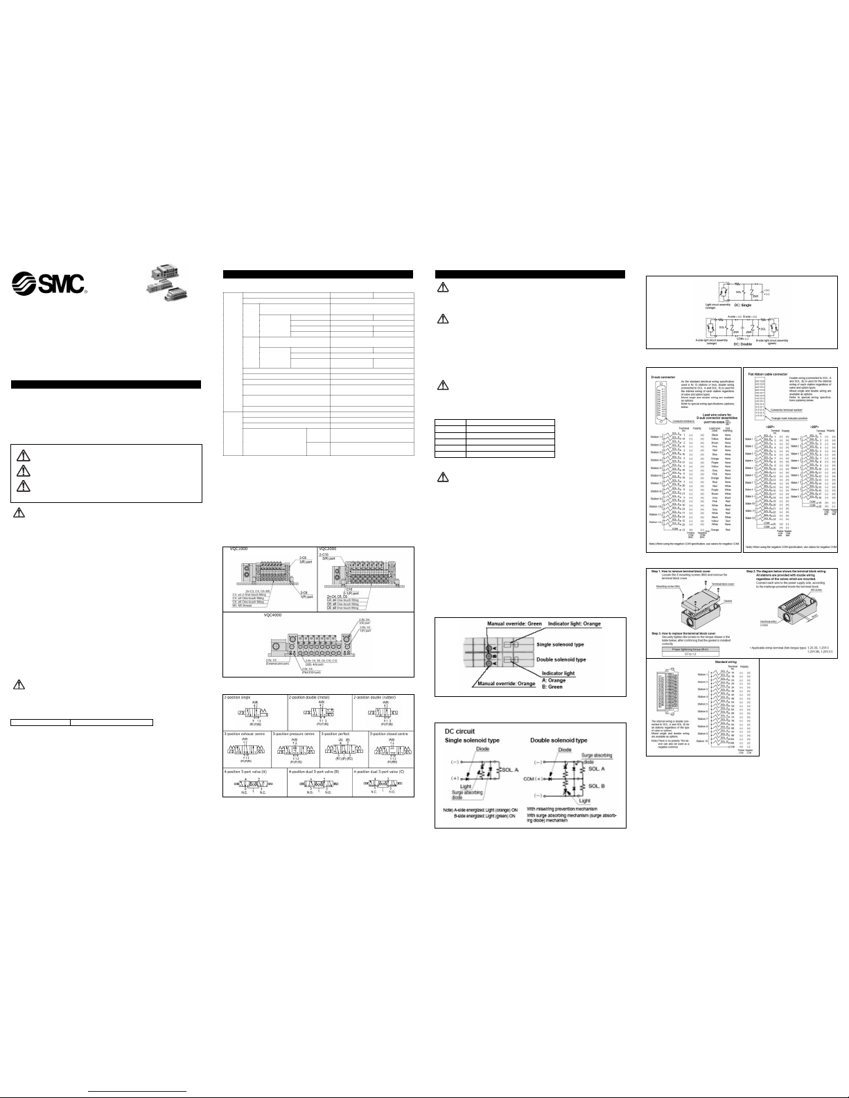
2.3 Circuit Symbols
Read this manual before using this product
The information within this document is to be used by pneumatically trained
personnel only.
For future reference, please keep manual in a safe place.
This manual should be read in conjunction with the current catalogue.
1 SAFETY RECOMMENDATION
1.1 General recommendation
These safety instructions are intended to prevent a hazardous situation and/or
equipment damage. These instructions indicate the level of potential hazard by label of
"Caution", "Warning" or "Danger". To ensure safety, be sure to observe ISO4414
(Note1)
,
JIS B 8370
(Note2)
and other safety practices.
Note 1:ISO 4414:Pneumatic fluid power - General rules relating to systems.
Note 2:JIS B 8370:Pneumatic system axiom.
WARNING:
• The compatibility of pneumatic equipment is the responsibility of the person
who designs the pneumatic system or decides its specifications.
Since the products specified here are used in various operating conditions, their
compatibility for the specific pneumatic system must be based on specifications or
after analysis and/or tests to meet your specific requirements.
• Only trained personnel should operate pneumatically operated machinery
and equipment.
Compressed air can be dangerous if an operator is unfamiliar with it Assembly,
handling or repair of pneumatic systems should be performed by trained and
experienced operators.
• Do not service machinery/equipment or attempt to remove component until
safety is confirmed.
Inspection and maintenance of machinery/equipment should only be performed
after confirmation of safe locked-out control positions.
When equipment is to be removed, confirm the safety process as mentioned above.
Switch off air and electrical supplies and exhaust all residual compressed air in the
system.
Before machinery/equipment is re-started, ensure all safety measures to prevent
sudden movement of cylinders etc. (Bleed air into the system gradually to create
backpressure, i.e. incorporate a soft-start valve).
• Contact SMC if the product is to be used in any of the following conditions:
Conditions and environments beyond the given specifications, or if product is used
outdoors.
Installations in conjunction with atomic energy, railway, air navigation, vehicles,
medical equipment, food and beverage, recreation equipment, emergency stop
circuits, press applications, or safety equipment.
An application, which has the possibility of having negative effects on people,
property, or animals, requiring special safety analysis.
CAUTION:
Ensure that the air supply system is filtered to 5 micron.
1.2 Conformity to standard
This product is certified to and complies with the following standards:
3 INSTALLATION
WARNING:
Do not install unless the safety instructions have been read and understood.
3.1 Environment
WARNING:
Do not use in an environment where the product is directly exposed to corrosive
gases, chemicals, salt water, water or steam.
Do not use in an explosive atmosphere.
The product should not be exposed to prolonged sunlight. Use a protective cover.
Do not mount the product in a location where it is subject to strong vibrations
and/or shock. Check the product specifications for above ratings.
Do not mount the product in a location where it is exposed to radiant heat.
3.2 Piping
CAUTION:
Before piping make sure to clean up chips, cutting oil, dust etc.
When installing piping or fitting into a port, ensure that sealant material does not
enter the port inside. When using seal tape, leave 1.5 to 2 threads exposed on the
end of pipe/fitting.
3.3 Electrical connection
CAUTION:
When DC power is connected to a solenoid valve equipped with light and/or surge
voltage suppressor, check for polarity indications.
For polarity indications:
1. No diode to protect polarity: if polarity connection is wrong, the diode in the
valve or switching device at control equipment or power supply may be
damaged.
2. With diode to protect polarity: if polarity connection is wrong, the valve does
not switch.
3.3.2 Cable safety instructions
1. Avoid miswiring, as this can cause malfunction, damage and fire in the unit.
2. To prevent noise and surge in signal lines, keep all wiring separate from
power lines and high voltage lines. Otherwise, this can cause a malfunction.
3. Check wiring insulation, as defective insulation can cause damage to the unit
when excessive voltage or current is applied.
4. Do not bend or pull cables repeatedly, and do not place heavy objects on
them or allow them to be pinched. This can cause broken
3.3.3 Light/Surge voltage suppressor VQC1000/2000
Indicator lights are all positioned on one side for both single solenoid and double
solenoid type valves.
For double solenoid type, 2 colors that are same as the manual override are used to
indicate the energization of A-side or B-side.
3.3.4 Internal wiring specification
VQC1000/2000
CAUTION: Operator error could result in injury or equipment damage.
WARNING: Operator error could result in serious injury or loss of life.
DANGER: In extreme conditions, there is a possible result of serious
injury or loss of life.
VQC4000
3.3.5 Electrical Wiring
D-sub connector (F kit) Flat cable connector (P kit)
Terminal box kit (T kit)
VQC-TFJ40GB
Installation and Maintenance Manual
5 Port Solenoid Valve, Series VQC
EMC Directive 89/336/EEC EN61000-6-2, EN55011, EN61000-4-5
X
Valve Configuration
Metal seal
Rubber seal
Fluid
Air/Inert gas
Max. operating pressure
0.7MPa (High pressure type:
1.0MPa)
(Note 4)
Single
0.1MPa
0.15MPa
Double
0.1MPa
3-position
0.1MPa
0.2MPa
VQC1000/
2000
Min.
operating
pressure
4-position - 0.15MPa
Max. operating pressure
(Note 3)
1.0MPa (0.7MPa)
Single
0.15MPa
0.2MPa
Double
0.15MPa
VQC4000
Min.
operating
pressure
3-position
0.15MPa
0.2MPa
Proof pressure
1.5MPa
Ambient and fluid temperature
-10° to 50°C
(Note 1)
Lubrication
Not required
Manual override
Push type/Locki ng type
(tool required) optional
Impact resistance/
Vibration resistance
150/30 m/s2
(Note 2)
Valve specification
Enclosure
IP67
Rated coil voltage
12VDC, 24VDC
Allowable voltage fluctuation
±10% of rated voltage
Coil insulation type
Equivalent to B type
24VDC
1W DC (42mA),
0.5W DC (21mA)
Electrical
specification
Power consumption
(current)
12VDC
1W DC (83mA),
0.5W DC (42mA)
Thread Appropriate tightening torque (Nm)
Rc(PT) 1/8 7 to 9
Rc(PT) 1/4 12 to 14
Rc(PT) 3/8 22 to 24
Rc(PT) 1/2 28 to 30
Rc(PT) 3/4 28 to 30
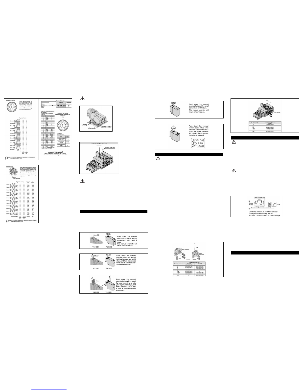
Multi connector kit (M kit)
Lead wire cable kit (L kit)
3.4 Mounting
If air leakage increases or equipment does not operate properly, stop
operation.
After mounting, repairs, or equipment modification, connect the compressed air
and power supplies, and perform appropriate function and leakage inspections to
confirm that the unit is mounted properly.
Instruction manual
Mount and operate the product only after reading the manual carefully and
understanding its contents. Always keep the manual handy for easy reference.
Painting and coating
Warnings or specifications printed or pasted on the product should not be erased,
removed or covered up.
Solenoid valve removal and mounting VQC1000/2000
Removal steps
1. Loosen the clamp screws until they turn freely. (The screws do not come out.)
2. Remove the solenoid valve from clamp B by lifting the coil side of the valve
while pushing on the screw top. If pushing down on the screw is difficult, you
can alternately press down on the valve gently in the area near the manual
override.
Mounting steps
1. Push the clamp screws. Clamp A opens. Now insert the end plate hook of the
valve into clamp B from an angle.
2. Push the valve down into place. (When you release the screws, the valve will
be locked into clamp A.)
3. Tighten the clamp screws with a tightening torque of 0.25 to 0.35N-m for
VQC1000 and 0.5 to 0.7N m for VQC2000.
CAUTION:
Do not let foreign matter stick on the seal side of the gasket and solenoid, as this will
cause air leakage.
Valve mounting VQC4000
After confirming that the gasket is installed correctly, securely tighten the mounting
screws according to the tightening torque shown below.
3.5 Lubrication
CAUTION:
SMC products have been lubricated for life at manufacturer, and do not require
lubrication in service.
If a lubricant is used in the system, use turbine oil Class 1(no additive), ISO VG32.
Once lubricant is used in the system, lubrication must be continued because the
original lubricant applied during manufacturing will be washed away.
1. The valve has been lubricated for life at the factory, and does not require any
further lubrication.
2. Should you wish to apply additional lubrication, however, please be sure to use ISO
VG32 Class 1 turbine oil (without additives).
Please be aware, however, that once additional lubrication is applied, it must be
continued to avoid malfunctions, as the new lubricant will completely cancel out the
original lubrication.
4 SETTINGS AND PROGRAMMING
Manual override
Since connected equipment will operate when the manual override is activated, confirm
that conditions are safe prior to activation.
The non-locking push type (tool required) is standard, and the slotted locking type (tool
required) is optional.
VQC1000/2000
Non-locking push type (tool required)
Slotted locking type (tool required) <Optional>
Locking type (manual) <Optional>
VQC4000
Non-locking push type (tool required)
Locking type (manual) <Optional>
5 MAINTENANCE
WARNING:
Not following proper procedures could cause the product to malfunction and could
lead to damage to the equipment or machine.
If handled improperly, compressed air can be dangerous. Assembly, handling and
repair of pneumatic system should be performed by qualified personnel only.
Drain: remove condensate from the filter bowl on a regular basis.
Shut-down before maintenance: before attempting any kind of maintenance make
sure the supply pressure is shut off and all residual air pressure is released from
the system to be worked on.
Start-up after maintenance: apply operating pressure and power to the equipment
and check for proper operation and possible air leaks. If operation is abnormal,
please verify product set-up parameters.
Do not make any modification to the product.
Do not disassemble the product, unless required by installation or maintenance
instructions.
Perform maintenance procedures as shown in the instruction manual.
If handled improperly, malfunction or damage of machinery or equipment may
occur.
Equipment removal and supply/exhaust of compressed air
When equipment is to be removed, first confirm that measures are in place to
prevent dropping of driven objects and run-away of equipment, etc. Then cut the
supply air pressure and electric power, and exhaust all compressed air from the
system using its residual pressure release function.
Infrequent operation
Valves should be switched at least once every 30 days to prevent malfunction. (Use
caution regarding the air supply.)
Manual override operation
When the manual override is operated, connected equipment will be actuated.
Confirm safety before operating.
Replacing one-touch fittings
Cylinder port fittings are available in cassette type and can be replaced easily.
Fittings are secured with a retaining clip that is inserted from the top side of the
valve. After removing the valve, remove the clip with a flat head screw driver to
replace the fittings.
To mount a fitting, insert the fitting assembly until it stops and reinsert the
retaining clip to its designated position.
VQC1000/2000
VQC4000
6 LIMITATIONS OF USE
WARNING:
Do not exceed any of the specifications laid out in section 2 of this document or the
specific product catalogue.
1. Confirm all specifications.
The products featured in this catalog are designed only for use in
compressed air systems (including vacuum). Do not operate at pressures or
temperatures beyond the range of specifications, as this can cause damage
or malfunction. (Refer to specifications.) Contact SMC when using a fluid
other than compressed air (including vacuum).
2. Extended periods of continuous en-ergization
Contact SMC if valves will be continuously energized for extended periods
of time.
CAUTION:
1. Momentary en-ergization
If a double solenoid valve will be operated with momentary en-ergization, it
should be energized for at least 0.1 second.
However, depending on the secondary load conditions, it should be energized
until the cylinder reaches the stroke end position. If the valve is to be used
in an air blowing application, it should be energized continuously during the
application.
2. Leakage voltage
When using a C-R element (surge voltage suppressor) for protection of the
switching element, please keep in mind that leakage voltage will increase
due to leakage current flowing through the C-R element.
3. Low temperature operation
Avoid ambient temperatures outside the range of -10°C to 50°C. At low
temperatures, take any necessary steps to avoid solidification or freezing of
drainage and moisture.
4. For air blowing applications
When using solenoid valves for air blowing, use external pilot type valves.
Also, air supply to the external pilot port should be compressed air that is
within the pressure range prescribed in the specifications.
5. Mounting orientation
In the case of a single solenoid, the mounting orientation is unrestricted. In
the case of double solenoid or 3-position valves, mount so that the spool
valve is horizontal. Also, when mounting for an application that will inevitably
involve vibration or impact, mount so that the spool valve is at a right angle
to the direction of vibration. Do not use in applications where vibration or
impact exceed the product's specifications.
7 EUROPEAN CONTACT LIST
7.1 SMC Corporation
Country Telephone Country Telephone
Austria (43) 2262-62 280 Italy (39) 02-92711
Belgium (32) 3-355 1464 Netherlands (31) 20-531 8888
Czech Republic (420) 5-414 24611 Norway (47) 67 12 90 20
Denmark (45) 70 25 29 00 Poland (48) 22-548 50 85
Finland (358) 9-859 580 Portugal (351) 22 610 89 22
France (33) 1-64 76 1000 Spain (34) 945-18 4100
Germany (49) 6103 4020 Sweden (46) 8 603 12 00
Greece (30) 1- 342 6076 Switzerland (41) 52-396 3131
Hungary (36) 23 511 390 Turkey (90) 212 221 1512
Ireland (353) 1-403 9000 United Kingdom (44) 1908-56 3888
7.2 Websites
SMC Corporation www.smcworld.com
SMC Europe www.smceu.com
VQC-TFJ40GB
 Loading...