

SMC Networks VQ100 Series Installation And Maintenance Manual
Installation and Maintenance Manual
VQ100 Series Solenoid Valve
This manual should be read in conjunction with the current valve catalogue.
For future reference, please keep this manual in a safe place
Safety Instructions
These safety instructions are intended to prevent a hazardous situation and/or equipment damage.These instructions indicate the level
of potential hazard by label of “Caution”,“Warning” or “Danger”.
To ensure safety,be sure to observe ISO4414
(Note1)
, JIS B 8370
(Note2)
and other safety practices.
Note 1: ISO 4414:Pneumatic fluid power – Recommendations for the
application of equipment to transmission and control systems.
Note 2: JIS B 8370: Pneumatic system axiom.
CAUTION : Operator error could result in injury or
equipment damage.
WARNING: Operator error could result in serious
injury or loss of life.
DANGER : In extreme conditions, there is a
possible result of serious injury or loss of life.
WARNING
1. The compatibility of pneumatic equipment is the responsibility of the person who designs the pneumatic system
or decides its specifications.
Since the products specified here are used in various operating
conditions, their compatibility for the specific pneumatic system
must be based on specifications or after analysis and/or tests to
meet your specific requirements.
2. Only trained personnel should operate pneumatically
operated machinery and equipment.
Compressed air can be dangerous if an operator is unfamiliar
with it.Assembly, handling or repair of pneumatic systems should
be performed by trained and experienced operators.
3. Do not service machinery/equipment or attempt to
remove component until safety is confirmed.
1) Inspection and maintenance of machinery/equipment should
only be performed after confirmation of safe locked-out
control positions.
2) When equipment is to be removed, confirm the safety process
as mentioned above.Switch off air and electrical supplies and
exhaust all residual compressed air in the system.
3) Before machinery/equipment is re-started, ensure all safety
measures to prevent sudden movement of cylinders etc.
(Bleed air into the system gradually to create back-pressure,
i.e. incorporate a soft-start valve).
4. Contact SMC if the product is to be used in any of the
following conditions:
1) Conditions and environments beyond the given specifica-
tions, or if product is used outdoors.
2) Installations in conjunction with atomic energy, railway, air
navigation, vehicles,medical equipment, food and beverage,
recreation equipment, emergency stop circuits, press
applications, or safety equipment.
3) An application which has the possibility of having negative
effects on people, property, or animals, requiring special
safety analysis.
CAUTION
Ensure that the air supply system is filtered to 5 micron.
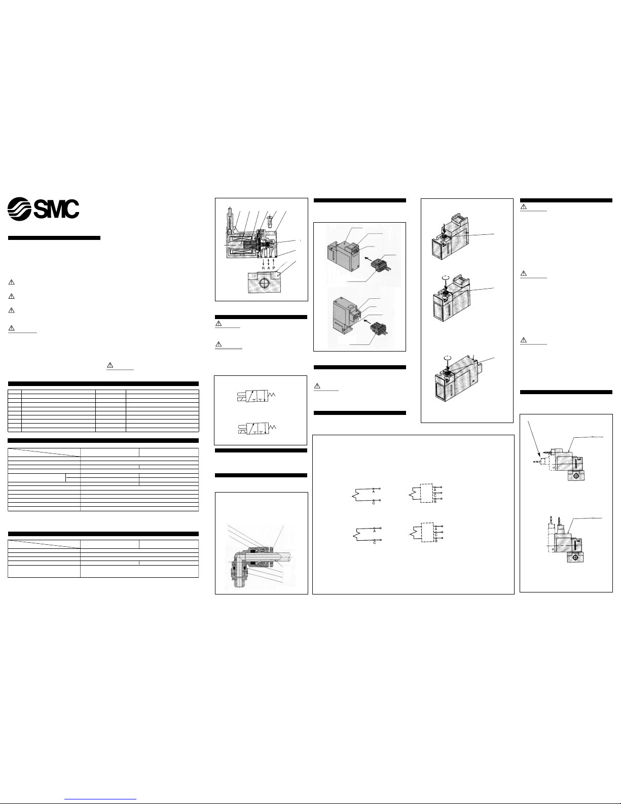
Main parts (Fig 1)
No. Description Material Note
1 Solenoid coil ––
2 Body Resin
3 Fixed iron core SUS
4 Movable iron core assembly SUS · Resin
5 Return spring SUS
6 Poppet NBR
7 Philips/ordinary round head screw Carbon steel AXT632-7-3 (M1.7x14)
8 Interface gasket NBR AXT782-11
9 Subplate ZDC AXT662-1-1/2 (1: M5,2: M3)
Valve specifications
Specifications 1 wattage
specifications
0.5 wattage
specifications
Item 0.7 MPa 0.7 MPa
Type 3 port direct operated poppet type (NC)
Fluid Air · inert gas
Max. operating pressure 0.7MPa (8.2 kgf/cm2) 0.7MPa (7.1 kgf/cm2)
Min. operating pressure 0MPa (0 kgf/cm2)
Effective orifice PRA 0.28mm2(Cv 0.016) 0.14mm2(Cv 0.008)
ARR 0.36mm2(Cv 0.02) 0.20mm2(Cv 0.011)
Response time Note 1 ON: 3.5ms,OFF: 2ms ON: 3.5ms, OFF: 2.5ms
Ambient and fluid temperature -10~+50°C Note 2
Lubrication Not required
Manual override Non-locking recessed type/Locking tool type Note 3
Mounting orientation Free
Protection structure IP40
Weight 12.6g (L/M type connector,without subplate)
Note 1:As per JISB8375-1981 (with indicator light and surge voltage suppressor; clean air), dispersion accuracy ±1ms.
Note 2: Use dry air to prevent dew condensation when operating at low temperature.
Note 3: Locking type is optional specification.
Solenoid specifications
Specifications 1 wattage
specifications
0.5 wattage
specifications
Item 0.7 MPa 0.7 MPa
Coil rated voltage 24VDC, 12VDC
Allowable voltage ±10% of rated voltage
Type of coil insulation Class B
Power consumption 1WDC 0.5WDC
Electrical entry
Plug-in, L/M type connector
(with indicator light and surge voltage suppressor)
Installation
CAUTION
Ensure all air and power supplies are isolated before commencing
installation.
WARNING
DO NOT INSTALL THESE VALVES IN EXPLOSIVE ATMOSPHERES.
If these valves are exposed to water or oil droplets, ensure that the
valves are protected.
If it is intended to energise a valve for an extended period please
consult SMC.
Tube connections-push-in fittings (Fig 2)
Ensure that the end of the tube 6 is cut square.
Push the tube 6 firmly into the fitting 7 until it stops.
Pull back on the tube 6 to ensure it is correctly gripped.
Tube disconnection (Fig 2)
Push down on the collet flange 2, via the release button 4, hold
down, and withdraw the tube 6.
Connection of plug connector (Fig 3)
Push the connector, in a straight line,onto the pins of the solenoid,
ensuring that the lip of the lever is securely positioned in the groove
of the solenoid cover.
Disconnection of plug connector (Fig 3)
Press the lever against the connector and pull the connector away
from the solenoid.
CAUTION
Do not exert excessive force on the wires, as this may cause contact
failure.
Wiring specifications (Fig 4)
The lead wires are connected to the valve as shown below.Connect
each to the power supply side.
Solenoid manual override (Fig 5)
WARNING
Exercise extreme CAUTION when operating solenoid manual
overrides, as connected equipment will commence operation.
Push non-locking type
Push down on the manual button 1 (Fig 5) until it stops (ON).
Hold this position whilst carrying out function checks.
Release the manual override button and the override will re-set to the
OFF position.
Locking type manual override (Fig 5)
Turn the manual override clockwise through 180°,using a small slotted screwdriver,until the mark P lines up with the No. 1.
Push down on the button until the override locks (ON) position.
WARNING
In this position the manual override is mechanically locked ON.
Un-locking (Fig 5)
Turn the manual override anti-clockwise through 180°,using a small
slotted screwdriver until the mark Plines up with the No.0.
Remove the screwdriver and the manual override will re-set to the
(OFF) position.
Latching Type (Fig 5)
Locking (Fig 5)
Turn the manual override clockwise 180°using a small slotted screwdriver until the mark P lines up with the letter A.
Push the override button down until it locks in position (ON).
WARNING
In this position the manual override is mechanically locked in the ON
position.
Un-locking
Turn the manual override anti-clockwise through 180° until the mark
P lines up with the letter B.
Remove the screwdriver, and the Manual override will re-set to the
OFF position.
Indicator light and surge suppressor (Fig 6a)
In the latching type, A (set) side and B (re-set) side energisation are
indicated by two colours,which match the colours of the manual override buttons. See below (Fig 6a)
019A/ENG
Symbol
Fig 2
Fig 4
Fig 6a
Fig 1
Fig 3
Fig 5
Latching type specification
1 Guide
2 Collet
3 Chuck
4 Release button
5 Packing
6 Tube
7 Body
8 O-ring
9 Stud
DC positive COM
DC negative COM
SOL.
Latching solenoid type
Single solenoid type
Lead wire colour
(-) Black
(+)Red
(-) White
SOL.
Single solenoid type
Lead wire colour
(+)Red
(-) Black
Non-locking recessed type
Latching type
Locking recessed type
Locking tool type (option)
1
2
3
4
1
2
3
5
6
7
8
9
Cover
Cover
Groove
Groove
Pin
Pin
Lever
Connector
Connector
Simultaneously
energised
protection
circuit
set
COM.
reset
Latching solenoid type
Lead wire colour
(+)Red
(-) Black
(+)White
Simultaneously
energised
protection
circuit
set
COM.
reset
SOL.
Indicator light
• ON
: Orange
(Set)
• (Reset) : Green
Indicator light
• ON
: Orange
(Set)
• (Reset) : Green
M type plug connector
Note: Dotted line shows latching type
L type plug connector
1 3 4 5 7 2
6
8
9
Lead wire colour
(-) Black
(+)Red
Valve specifications
(A)
2
3
(R)1(P)
3
(R)1(P)
(A)
2
Wiring specifications
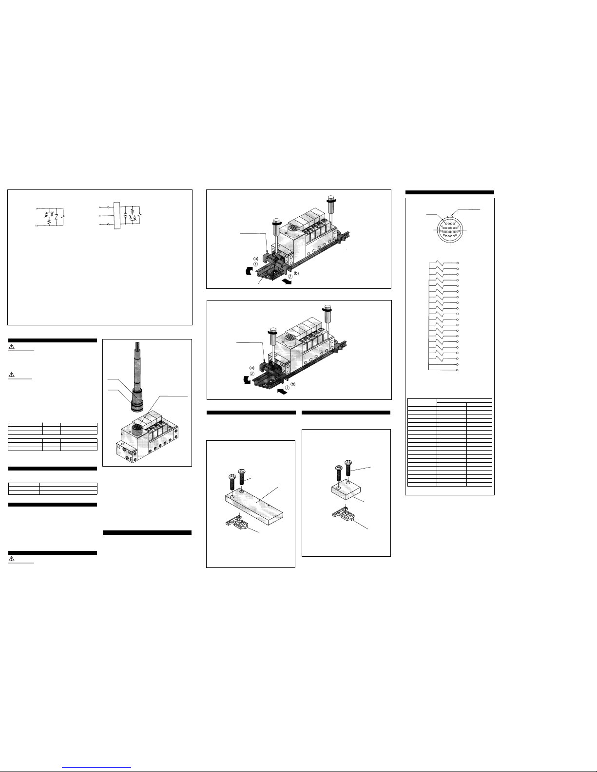
Blanking plate (Fig 12) (VVQ100-10A-1)
This type of blanking plate is fitted to multi-connector manifolds.
Ensure that the gasket 1 is correctly fitted.
Fit the blanking plate 2 onto the manifold station.
Fit and tighten the holding down screws 3 to the same torque
figures as the valve holding down screws (see above).
Blanking plate (Fig 13) (VVQ100-10A-2)
This type of blanking plug is fitted to standard multi-connector
manifolds (plug lead).
Fitting as above.
Wiring specification (Fig 6b)
WARNING
Latching solenoid
The latching solenoid is equipped with a self-holding mechanism,
which permits a moveable iron core 4 (Fig 1),in the solenoid, to hold
the 'set' position.
CAUTION
Do not employ simultaneous ON and OFF signals, as a 10ms energisation time is required for self-latching.
Avoid using these valves in applications involving excessive vibration
(10G or more).
Do not use in high magnetic fields.
At despatch the valve is set in the 'un-latched' mode. However it is
possible that it could move to the 'latch' position during transit.Before
operating this valve ensure that it is set to the 'un-latch' position.
See chart below (Fig 7).
Latching Passage Indicator light
A-C ON (Set) 1(P)R2(A) Orange
B-C ON (Reset) 2(A)R3(R) Green
Single Passage Indicator light
A-C ON 1(P)R2(A) Orange
OFF 2(A)R3(R) ––
Fittings
Tighten fittings into the valve using the following torque figures (Fig 8).
Mounting thread Correct clamping torque N-m (kgf-cm)
M5 1.5~2.0 (15~20)
M3 0.3~0.5 (3~5)
Multi-connector (Fig 9)
Connection
When fitting a connector align the positioning key 1 grooves and
ensure that the connector is vertical when inserting and that it locks
into position.
Disconnection
To disconnect the connector,lift the locking ring 3 and remove the
body 2 in a straight line (vertically).
Maintenance
WARNING
Before carrying out any form of maintenance ensure all air and power
supplies are isolated.
Removing a valve from the sub-base (Fig 11)
Disconnect the electrical connector (Fig 3).
Remove the valve holding down screws 7 (Fig 1).
Lift off the valve.
Retain the gasket.
Refitting a valve to a sub-base
Refit the gasket to the sub-base ensuring correct orientation.
Replace the valve.
Refit the valve holding down screws.
Torque screws to the following figure:
0.9 kgf/cm.
Mounting/Removing from a DIN-rail (Fig 10)
Removing
Loosen the clamp screw of the end plate 1 on both ends of the
manifold. Lift side (a) of the manifold base, slide the end plate in the
direction of 2 to remove.
Mounting
Hook side (b) of the manifold base onto the DIN-rail.
Press down side (a) and clip the end plate onto the DIN-rail.
Tighten the clamp screws to the following torque figures:
0.8 N-m~1.2 N-m (8~12 kgf/cm).
Fig 6b
Fig 10
Fig 14
Fig 11
Fig 7
Fig 8
Note 3:The solenoid valve channel is,
A-(set): I (P)R2(A)
B-(reset) : 2AR3(R)
Note 4:Applicable to negative COM
specification model.
Single solenoid type (DC) Latching solenoid type (DC)
Note 1:Single type: non-polarity
ON: light (orange) illuminates.
Note 2: A (set) side energisation:
A light (orange) illuminates.
B (reset) side energisation:
B light (green) illuminates.
Equipped with a wiring error prevention
(stop diode) mechanism and a surge absorption.
A (-) Set
C (+) COM
B (-) Reset
Fig 9
Fig 12
Fig 13
1 station
2 stations
3 stations
4 stations
5 stations
6 stations
7 stations
8 stations
9 stations
10 stations
11 stations
12 stations
13 stations
14 stations
15 stations
16 stations
17 stations
18 stations
1
2
3
4
5
6
7
8
9
10
11
12
13
14
15
16
17
18
19
20
SOL.
SOL.
SOL.
SOL.
SOL.
SOL.
SOL.
SOL.
SOL.
SOL.
SOL.
SOL.
SOL.
SOL.
SOL.
SOL.
SOL.
SOL.
COM
COM
When you enquire about the product, please contact the following
SMC Corporation:
ENGLAND Phone 01908-563888 TURKEY Phone 212-2211512
ITALY Phone 02-92711 GERMANY Phone 6103-402-0
HOLLAND Phone 020-5318888 FRANCE Phone 01-64-76-10-00
SWITZERLAND
Phone 052-34-0022 SWEDEN Phone 08-603 07 00
SPAIN Phone 945-184100 AUSTRIA Phone 02262-62-280
Phone 902-255255 IRELAND Phone 01-4501822
GREECE Phone 01-3426076 DENMARK Phone 8738-0800
FINLAND Phone 09-68 10 21 NORWAY Phone 67-12 90 20
BELGIUM Phone 03-3551464 POLAND Phone 48-22-6131847
SOL.
A (-)
C (+)
SOL.
Simultaneously energised
protection circuit
1 Positioning key
2 Body
3 Ring
DIN-rail mounting
bracket
DIN-rail mounting
bracket
1
2
3
3
2
1
1
Blanking plate with 2 damp screws and gasket
Blanking plate with 2 damp screws and gasket
Pin No.
Positioning key
Multi-connector pin arrangement
Pin No.
Electrical wiring specifications
Terminal No./Lead wire colour
Terminal No.
Lead wire colour
Lead wire colour Dot marking
1 Black -–
2 Brown -–
3 Red -–
4 Orange -–
5 Yellow -–
6 Pink -–
7 Blue -–
8 Violet White
9 Grey Black
10 White Black
11 White Red
12 Yellow Red
13 Orange Red
14 Yellow Black
15 Pink Black
16 Blue White
17 Violet -–
18 Grey -–
19 Orange Black
20 Red White
 Loading...