

SMC Networks VQ0000 Series,VQ1000 Series,VQ2000 Series Installation And Maintenance Manual

Installation and Maintenance Manual
Series VQ0000/1000/2000 Series Solenoid Valve,
Body Ported Type (Metal/Rubber Seal)
This manual should be read in conjunction with the current valve catalogue
For future reference, please keep this manual in a safe place
Safety Instructions
These safety instructions are intended to prevent a hazardous situation and/or equipment damage.These instructions indicate the level
of potential hazard by label of “Caution”,“Warning” or “Danger”.
To ensure safety,be sure to observe ISO4414
(Note1)
, JIS B 8370
(Note2)
and other safety practices.
Note 1: ISO 4414:Pneumatic fluid power – Recommendations for the
application of equipment to transmission and control systems.
Note 2: JIS B 8370: Pneumatic system axiom.
CAUTION : Operator error could result in injury or
equipment damage.
WARNING : Operator error could result in serious
injury or loss of life.
DANGER : In extreme conditions, there is a
possible result of serious injury or loss of life.
WARNING
1. The compatibility of pneumatic equipment is the responsibility of the person who designs the pneumatic system
or decides its specifications.
Since the products specified here are used in various operating
conditions, their compatibility for the specific pneumatic system
must be based on specifications or after analysis and/or tests to
meet your specific requirements.
2. Only trained personnel should operate pneumatically
operated machinery and equipment.
Compressed air can be dangerous if an operator is unfamiliar
with it.Assembly, handling or repair of pneumatic systems should
be performed by trained and experienced operators.
3. Do not service machinery/equipment or attempt to
remove component until safety is confirmed.
1) Inspection and maintenance of machinery/equipment should
only be performed after confirmation of safe locked-out
control positions.
2) When equipment is to be removed, confirm the safety process
as mentioned above.Switch off air and electrical supplies and
exhaust all residual compressed air in the system.
3) Before machinery/equipment is re-started, ensure all safety
measures to prevent sudden movement of cylinders etc.
(Bleed air into the system gradually to create back-pressure,
i.e. incorporate a soft-start valve).
4. Contact SMC if the product is to be used in any of the
following conditions:
1) Conditions and environments beyond the given specifica-
tions, or if product is used outdoors.
2) Installations in conjunction with atomic energy, railway, air
navigation, vehicles,medical equipment, food and beverage,
recreation equipment, emergency stop circuits, press
applications, or safety equipment.
3) An application which has the possibility of having negative
effects on people, property, or animals, requiring special
safety analysis.
CAUTION
Ensure that the air supply system is filtered to 5 micron.
Standard specifications (Fig 2)
Type of seal Metal seal Rubber seal
Fluid Air • Inert gas Air • Inert gas
Note3)
Max. operating pressure 0.7MPa (High pressure type: 0.8MPa)
Valve specifications
Min. operating pressure
Single 0.1MPa (1.0 kgf/cm2) 0.15MPa (1.5 kgf/cm2)
Double 0.18MPa (1.8 kgf/cm
2
) 0.18MPa (1.8 kgf/cm2)
(latching)
3 position 0.1MPa (1.0 kgf/cm2) 0.2MPa (2.0 kgf/cm2)
Proof pressure 1.5MPa (15.3 kgf/cm2)
Ambient and fluid temperature -10~+50°C
Note 1)
-5~+50°C
Note 1)
Lubrication Not required
Manual override
Note 2)
Non-locking push type/push-locking
tool, lever types (option)
Protection structure IP40
Coil rated voltage 12, 24VDC
Allowable voltage ±10% of rated voltage
Solenoid Type of coil insulation Class B
specifications Power consumption 24VDC 1WDC (42mA),
Note 3)
1.5WDC (63mA),
Note 4)
0.5WDC (21mA)
(current value) 12VDC 1WDC (83mA),
Note 3)
1.5WDC (125mA),
Note 4)
0.5WDC (42mA)
Note 1: Use dry air to prevent dew condensation when operating at low temperature.
Note 2: Push-locking type (B) or (C) should be selected for double (latching) type.
Note 3:Value for low-wattage (0.5W) specifications.
Note 4:Value for high-pressure (1.5W) type specifications.
Tube connection (push-in fitting) (Fig 5)
Ensure that the end of the tube is cut square.Push the tube firmly into
the fitting until it stops. Pull back on the tube to ensure that it is
engaged.
Replacement of cylinder port fittings
The cylinder port fittings are of a cassette type for easy replacement
(except for VQ0000).The fittings are blocked by a clip inserted from
the top of the valve.Remove the clip with a screwdriver to remove fittings.To replace, insert the fitting assembly until it strikes against the
inside wall and then re-insert the clip to the specified position.
Disconnection
Push down on the collet flange, hold down,and withdraw the tube.
Electrical connection, plug lead only (plug connector) (Fig 4)
Push the connector onto the pins of the solenoid valve in a straight
line, ensuring that the lip of the lever is securely positioned in the
groove of the solenoid cover.
Disconnection (Fig 4)
Press the lever against the connector and pull the connector in a
straight line away from the solenoid.
NOTE
Plug-in units are factory pre-wired to specification (Fig 8).
Electrical disconnection D-sub connector (Fig 8)
Loosen the two captive screws 1, pull off the connector 2.
Electrical re-connection of D-sub connector (Fig 8)
Insert connector 2 into the body 3.
CAUTION
Ensure that the connector enters directly onto the pins in the body.
Tighten the two retaining screws 1.
Electrical dis-connection flat cable connector (Fig 11)
Lift the two clamps 1 outwards from the connector 2.
Remove the connector 2 out of the body 3.
Re-fitting is the reverse of the above.
Wiring
Ensure that control wiring is separated from power wiring to prevent
noise generation.
Manual override
WARNING
Exercise extreme CAUTION when operating solenoid valve manual
overrides as connected equipment will commence operation.
Push non-locking type (Fig 6)
Push down on the manual override button 1 until it stops (ON). Hold
this position whilst carrying out function checks. Release the manual
override button and the override will re-set to the (OFF) position.
Push locking type manual override (Fig 6)
Push down on the manual override button, using a small screwdriver
until it stops. Turn the button through 90° clockwise to lock. (180°
VQ0000).
CAUTION
In this position the override will be mechanically 'locked' in the ON
position.
Un-locking
Turn the manual override using a small screwdriver through 90°(180°
VQ0000) anti-clockwise. Remove the screwdriver and the manual
override will re-set.
Raised button type locking override (Fig 6)
Push down on the raised button until it stops.Turn the button through
90° clockwise by hand.
CAUTION
In this position the override is mechanically 'locked' in the ON
position.
Un-locking manual override
Turn the raised button through 90° anti-clockwise by hand. Release
the button and the manual override will re-set to the OFF position.
Lamp and surge voltage suppressor (Fig 7)
All solenoid valves are equipped with lamp and surge protection as a
standard feature. The indicators are positioned on one end of the
valve, for both single and double solenoid types.The colours of the
indicator lamps match the colours of the manual override buttons.
D-sub connector/flat cable connector/terminal block
Wiring specification (Fig 12)
With the A side solenoid of the 1st station,as No. 1 (i.e. connected to
No. 1 terminal), wires are connected in the order indicated by the
arrow in Fig 12.
NOTE: No terminal should be left vacant.
Maintenance
WARNING
Before carrying out any maintenance work ensure that air and power
supplies are ISOLATED.
Plug lead unit/flip type
Removal of a Valve (Fig 5b)
1. Disconnect electrical connector. (See above.)
2. Slacken lower tie bolt 3 2~3 turns.Remove the upper tie bolt 6
and retain. Separate the valves either side of the valve to be
removed approximately 2mm. Lift the valve to be changed off the
manifold, in the direction of the arrow J.
Replacing a valve (Fig 5b)
Reverse the above procedure to replace a valve.
023a/eng
Installation
CAUTION
Ensure all air and power supplies are isolated before commencing
installation.
WARNING
DO NOT INSTALL THESE VALVES IN EXPLOSIVE ATMOSPHERES.
If these valves are exposed to water or oil droplets, ensure that the
valves are protected.
If it is intended to energise a valve for an extended period please
consult SMC.
Fig 1
Symbol
2 position single 3 position closed centre
3 position exhaust centre
3 position pressure centre
2 position double (latching)
Metal
seal
Rubber
seal
Plug lead unit/flip type (Fig 3)
Fig 3
Fig 5
Fig 12
Fig 6
Fig 11
Fig 8
Fig 4 Fig 7
Note 1:A-side energization: A light (orange) illuminates. B-side energization: B light (green) illuminates.
Equipped with a wiring error prevention (stop diode) mechanism and a surge absorption (ZNR/surge absorption
diode) mechanism.
Note 2:Applicable to negative COM specification models.
Note 3:In case of double (latching), the electromagnetic valve channel is, A- (set): PRA,BRR, (B- (reset): PRB, A RR
Connector
assembly
Connector
assembly
Connector
assembly
Type of
connection
Type of
connection
Type of
connection
P port
P port
P port
R port
R port
R port
A, B port
A, B port
A, B port
25-pin
VV5Q24
VV5Q14VV5Q04
Cover
Cover
Groove
Lever
Hook
Connector
AXT661-12
DC indicator
Socket
DXT170-71-1
Lead wire
0.2~0.33mm
2
(Max. O.D.
: ø1.7mm)
Groove
Pin
Pin
Type of connection
25-pin
Clip
Fittings assembly
P port
R port
A, B port
3
3
2
2
1
1
Cable
assembly
Electrical wiring specifications
D side
U side
1 2 3 -------------Stations
Non-locking push type
Push-locking tool type
Push-locking lever type
Bore:ø3.2
Bore:ø3.2
10 mm
3
2
1
Manual override: Orange
Single
solenoid type
Double
(latching)
type
Indicator light
A: Orange
B: Green
Indicator light
Orange
Manual override: Green
DC type circuit diagram
Single solenoid type (DC)
Double (latching) solenoid
type (DC)
A (-)
A -(Set)
C +(Com)
B - (Reset)
C(+)
Light
ZNR
SOL
SOL
Protection circuit
COM
COM
COM
COM
COM
F kit
D-sub connector
(In case of 25-pin)
P kit
Flat cable
connector
(In case of 26-pin)
T kit
Terminal block
(In case of
16 terminals)
Removal of manifold from DIN-rail (Fig 9)
Loosen the clamp screws 1 at both ends of the manifold. Lift side (a)
of the manifold base and slide the manifold in the direction of the figure (2).
Replacing the manifold onto the DIN-rail (Fig 9)
Hook side (b) onto the DIN rail. Press down side (a) to engage the
manifold onto the DIN rail.Tighten the two clamp screws 1.
NOTE:Tightening torque is as follows:
0.8N-m ~ 1.2N-m (8 ~ 12 kgf/cm)
Replacement of cylinder port fittings (Fig 5b)
Remove and retain clip K from the valve body L.Remove fittings 2
from the valve body.Fit replacement fittings into valve body, pushing
them into the body until they stop. Replace the retaining clip K into
the valve body.
Replacing silencer element (Fig 10)
Remove element cover retaining screws 1 from both ends of the
manifold (retain). Remove both element end covers 2 and retain.
Remove and replace both silencer elements 3, discard the originals.
Replace both element end covers. Re-fit element cover retaining
screws at both ends and tighten.
Plug lead unit/cassette type (Fig 15)
1 Valve
2 Fitting
3 Lower tie bolt
4 DIN-rail
5 Supply and exhaust block
6 Upper tie bolt
7 Solenoid pilot
8 Connector (electrical)
9 Collet
J Direction arrow
K Retaining clip (fittings)
L Valve body
Fig 5b
Fig 10
Fig 9 Fig 15
Fig 13
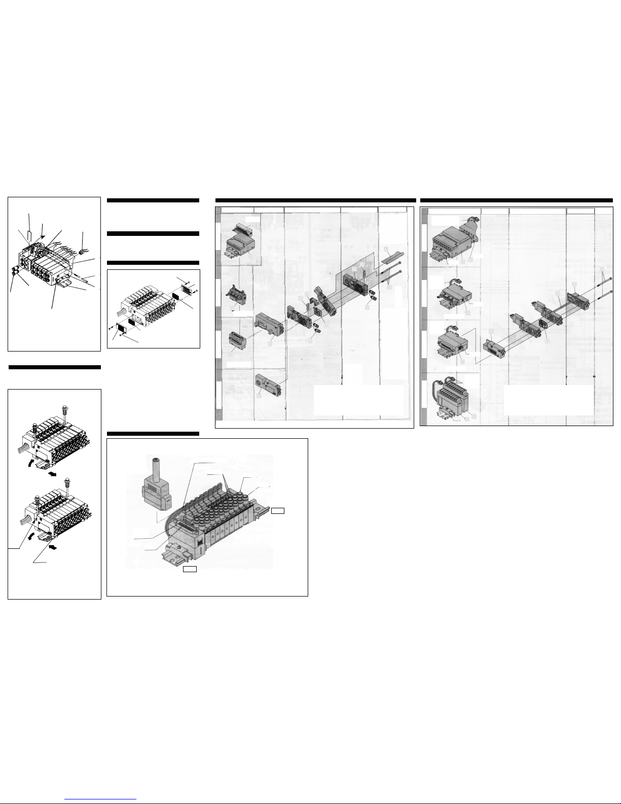
Exploded view of plug-in unit/flip type manifold (Fig 13)
Fig 14
Exploded view of plug lead unit/flip type (Fig 14)
1 SI unit-omron
2 Flat cable kit
3 D-sub kit
4 D-side end plate
5 D-side end plate
6 D-side end plate
7 Junction box assembly
8 Gasket
9 Clip
J Fitting assembly
K Tie rod bolt
L Junction cover
1 SI unit-omron
2 Flat cable kit
3 D-sub kit
4 Terminal block
5 Terminal block
6 D-side end plate assembly
7 U-side end plate assembly
8 Gasket
9 Tie rod bolt
J Guide rod
D-sub connector
When you enquire about the product, please contact the following
SMC Corporation:
ENGLAND Phone 01908-563888 GERMANY Phone 6103-402-0
ITALY Phone 02-92711 FRANCE Phone 1-64-76-10-00
HOLLAND Phone 020-5318880 SWEDEN Phone 08-603-07-00
SWITZERLAND
Phone 052-34-0022 AUSTRIA Phone 02262-62-280
SPAIN Phone 945-290600 IRELAND Phone 01-4501822
GREECE Phone 01-3426076 DENMARK Phone 8738-0800
FINLAND Phone 9-68-10-21 NORWAY Phone 67-12-90-20
BELGIUM Phone 03-3551464 POLAND Phone 48-22-6131847
TURKEY Phone 212-2211512
VQ Series
1
1
1
2
2
2
2
1
2
3
5
4
J
J
6
1
2
2
3
4
5
6
8
J
7
9
9
L
K
8
9
7
3
3
3
4
5
6
7
8
9
J
K
L
(a)
1
1
2
2
(b)
(a)
(b)
Hook
DIN
clamp
screw
Connector assembly
A, B port
R port
P port
25-pin
Type of
connection
D-side
U-side
Housing assembly and SI unit D side end plate assembly Valve and junction box assembly
U side end plate assembly
Station increase parts
Housing assembly and SI unit
Note 3)
D side end plate ass’y
Valve
U side end plate ass’y
Station increase
parts
S kitP kit
F kit
L kit
S kitP kitF kit
T kit
FS (side entry)
Note 4)
PS (side entry)
Note 1)
Note 1: S kit is composed of a flat cable housing assembly (AXT100-2-PU20) of 1 SI unit and 2 P kit (20-pin).
Note 2
Connector assembly
Note 2
Connector
assembly
Note 2
Connector
assembly
Note 2
Connector
assembly
Note 4
Note 4
Note 4
PS (side entry)
FS (side entry)
Note 1
Note 1: S kit is composed of a flat cable housing assembly (AXT100-2-PU20) of 1 SI unit and 2 P kit (20-pin).
Note 2: Since no connector assembly is included,order it separately.
Note 3:A housing assembly is not used for a C kit.
Note 4:A DIN rail clamping bracket rail is attached to each.
 Loading...