

SMC Networks VP300, VP500 Series, VP700 Series Series Manual
3 Port Solenoid Valve
Series
VP300/500/700
RoHS
compliant
0.55
w
1.55
w
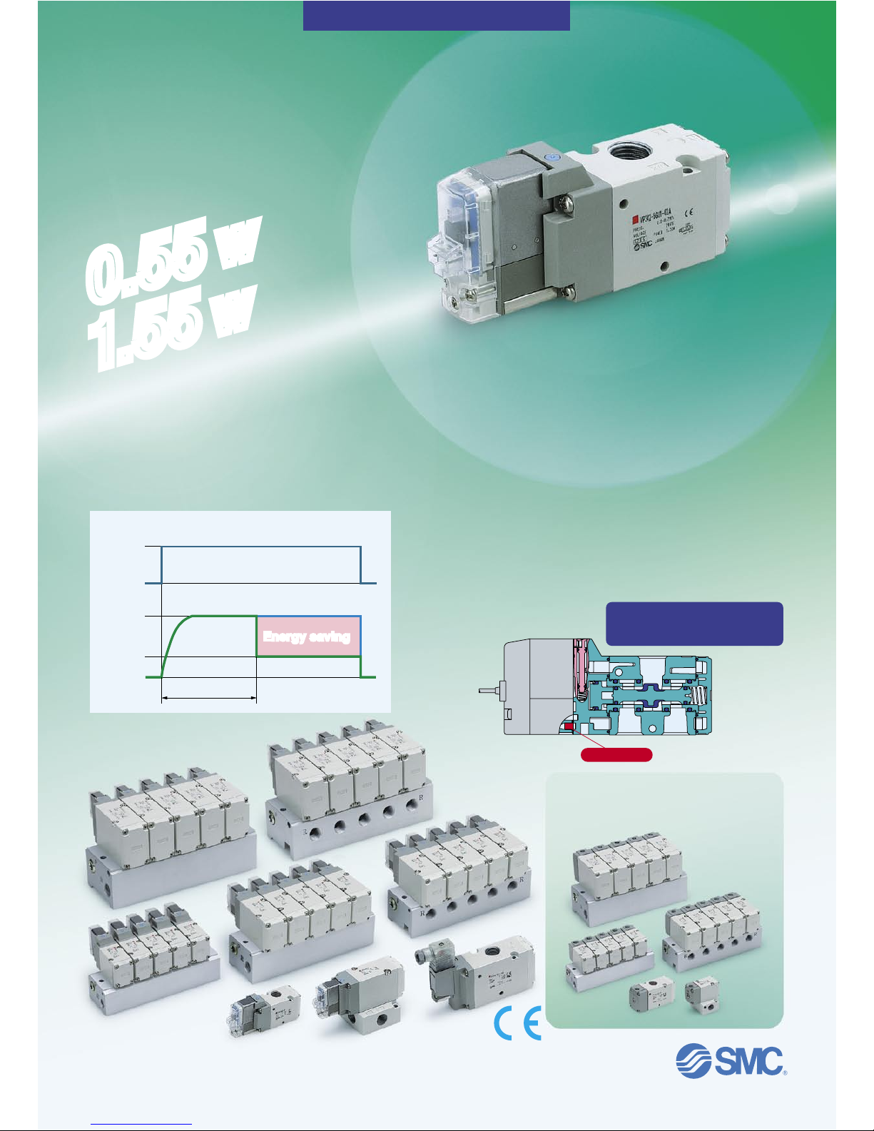
Built-in full-wave rectifier
(AC)
Noise reduction
Noise is considerably reduced by changing it to DC mode via
a full-wave rectifier.
Reduced apparent power
Conventional:
5.6
VA →
1.55
VA
Longer life expectancy:
50 million cycles or more
(Conventional: 20 million cycles)
∗
Based on SMC test conditions
Built-in strainer in the pilot valve
Unexpected troubles due to foreign matter can be prevented.
Note) Be sure to mount an air filter on the inlet side.
Rubber material: HNBR
Ozone-resistant specification
∗ The pilot valve poppet is made of FKM.
Strainer
Electrical power waveform of energy saving type
Applied voltage
Standard
With power saving circuit
40
ms
24
V
0
V
1.55
W
0.55
W
0
W
Energy savingEnergy saving
Reduced power consumption:
0.55
w
[
With power saving circui
t
]
1
.55
w
[
Standar
d
]
(Conventional: 2.0 W)
∗
With DC light
Power consumption reduced
by power saving circuit.
Power consumption is decreased by approx. 1/3 by reducing
the wattage required to hold the valve in an energized state.
(effective energizing time is over 40 ms at 24 VDC.) Refer to
electrical power waveform as shown below.
Series VP300
Air Operated Valve
Series VPA300
/
500/700
CAT.EUS11-97A-UK
1
(P)3(R)
(A)
2
1
(P)3(R)
(A)
2
1
(P)3(R)
(A)
2
X
1
(P)3(R)
(A)
2
1
(P)3(R)
(A)
2
1
(P)3(R)
(A)
2
X
1
(P)3(R)
(A)
2
X
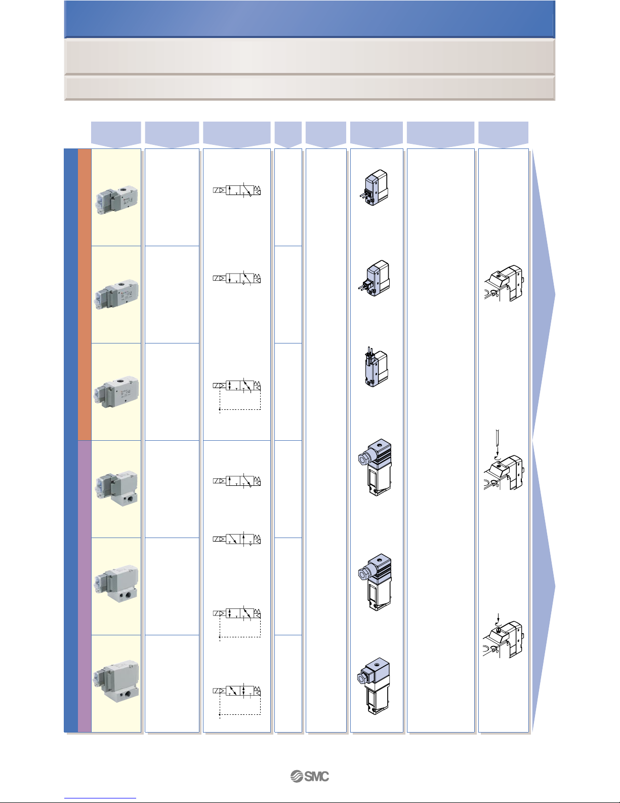
Base mounted Body ported
Solenoid valve
Series
Sonic conductance
C [dm3/(s·bar)]
Type of actuation
Internal pilot
N.C.
Grommet
Non-locking
push type
Push-turn
locking
slotted type
Push-turn
locking
lever type
L-type plug
connector
M-type plug
connector
DIN
terminal
DIN (EN1753
01-803)
terminal
Conduit
terminal
Internal pilot
N.C.
N.O.
External pilot
N.C.
N.O.
N.O.
External pilot
N.C./N.O.
Port
size
Voltage
Light/surge
voltage suppressor
Manual
override
Electrical
entry
VP300
VP500
VP700
VP300
VP500
VP700
12 VDC
24 VDC
100 VAC
200 VAC
110 VAC
220 VAC
240 VAC
P. 1
P.
8
1/8
1/4
1/4
3/8
3/8
1/2
1/8
1/4
1/4
3/8
3/8
1/2
4.2
8.9
15.3
3.8
8.8
15.0
Series VP300/500/700
Model Selection by Operating Conditions
q
Solenoid Valve: Single Unit
DC
With surge voltage
suppresso
r
With light/surge
voltage suppressor
With surge voltage
suppressor (Nonpolar)
With light/surge
voltage suppressor
(Non-polar)
AC
With light/surge
voltage suppressor
Note) Only DIN and conduit terminal types can be set for AC mode.
Note)
3(R) port
1/4
3(R) port
3/8
3(R) port
1/2
3(R) port
1/2
3(R) port
1/4
2(A) port
1/4
1(P) port
1/4
2(A) port
1/4
2(A) port
3/8
2(A) port
3/8
2(A) port
1/2
2(A) port
1/2
3(R) port
3/8
1(P) port
1/4
1(P) port
3/8
1(P) port
3/8
1(P) port
1/2
1(P) port
1/2
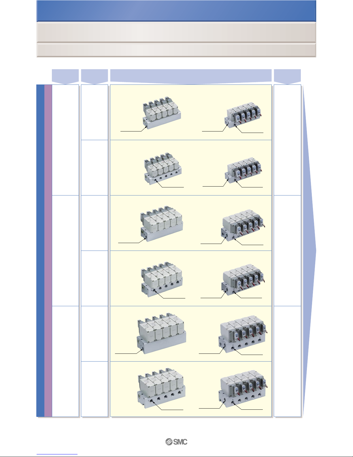
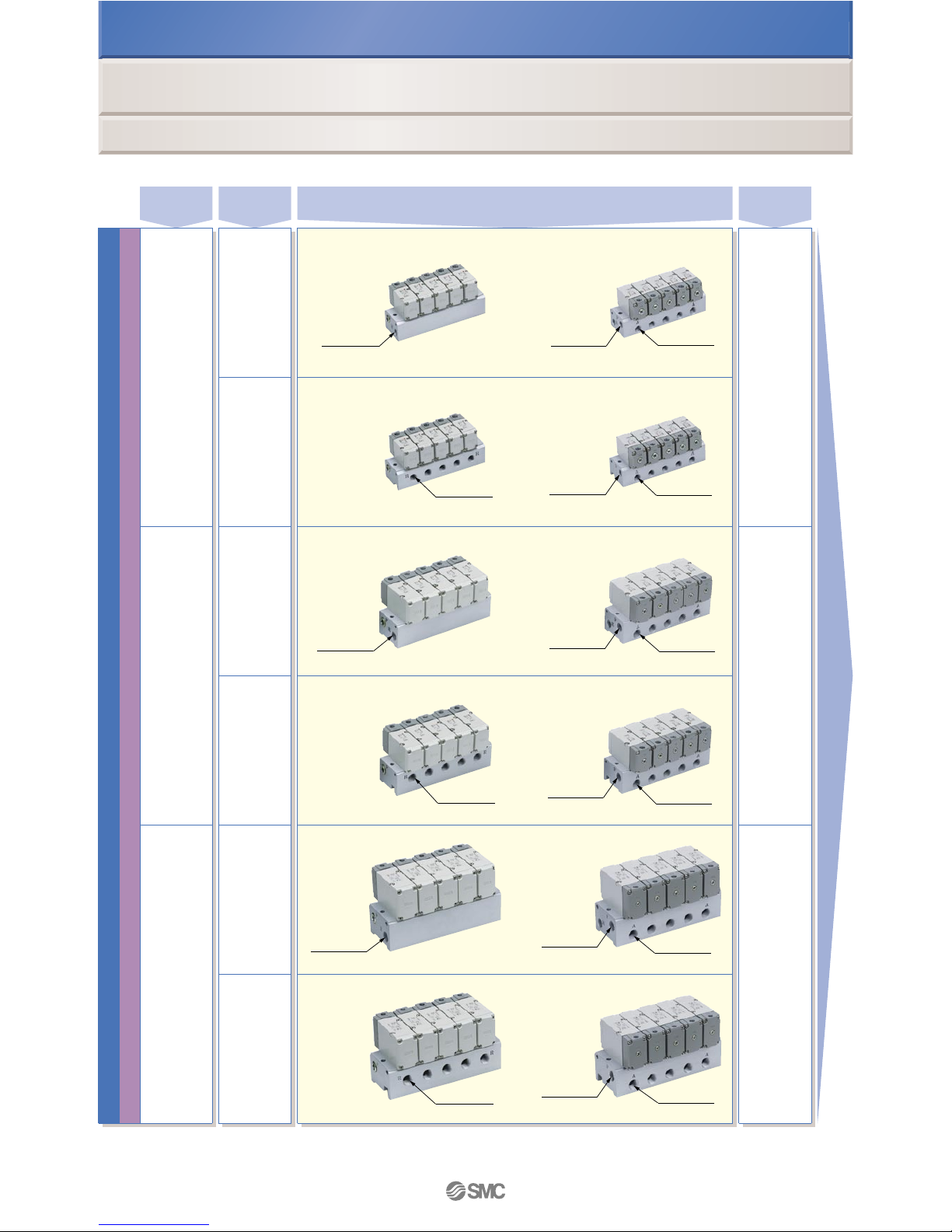
Base mounted
Solenoid valve
Series
EXH port
type
2 to 20
stations
2 to 20
stations
2 to 20
stations
Common EXH
Individual EXH
Common EXH
Individual EXH
Common EXH
Individual EXH
VV3P3-41
VV3P3-42
VV3P5-41
VV3P5-42
VV3P7-41
VV3P7-42
Manifold
base model
VP300
VP500
VP700
Applicable
stations
Note)
P. 15
Note) Supply pressure to 1(P) ports and exhaust air from 3(R) ports on both sides for 10 stations or more.
Series VP300/500/700
Model Selection by Operating Conditions
w
Solenoid Valve: Manifold
Features 1
3(R) port
1/4
3(R) port
3/8
3(R) port
1/2
3(R) port
1/2
3(R) port
1/4
2(A) port
1/4
1(P) port
1/4
2(A) port
1/4
2(A) port
3/8
2(A) port
3/8
2(A) port
1/2
2(A) port
1/2
3(R) port
3/8
1(P) port
1/4
1(P) port
3/8
1(P) port
3/8
1(P) port
1/2
1(P) port
1/2
Base mounted
Solenoid valve
Series
EXH port
type
2 to 20
stations
2 to 20
stations
2 to 20
stations
Common EXH
Individual EXH
Common EXH
Individual EXH
Common EXH
Individual EXH
VV3P3-41
VV3P3-42
VV3P5-41
VV3P5-42
VV3P7-41
VV3P7-42
Manifold
base model
VP300
VP500
VP700
Applicable
stations
Note)
P. 15
Note) Supply pressure to 1(P) ports and exhaust air from 3(R) ports on both sides for 10 stations or more.
Series VP300/500/700
Model Selection by Operating Conditions
w
Solenoid Valve: Manifold
Features 2
1
(P)3(R)
(A)
2
12
1
(P)3(R)
(A)
2
12
1
(P)3(R)
(A)
2
12
1
(P)3(R)
(A)
2
12
12
(A)
2
1
(P)3(R)
12
(A)
2
1
(P)3(R)
12
(A)
2
3
(R)1(P)
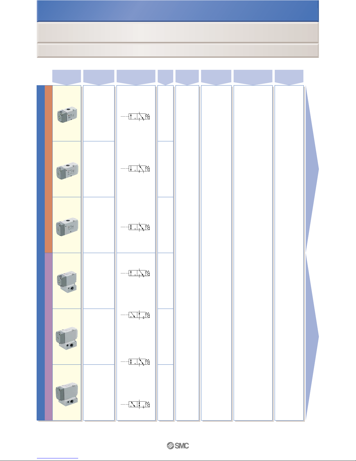
Air operated valve
N.C.
N.O.
For vacuum
N.C./N.O.
N.C.
N.O.
For vacuum
N.C.
N.O.
VPA300
VPA500
VPA700
VPA300
VPA500
VPA700
— ———
P. 25
P. 30
1/8
1/4
1/4
3/8
3/8
1/2
1/8
1/4
1/4
3/8
3/8
1/2
4.2
8.9
15.3
3.8
8.8
15.0
Series VPA300/500/700
Model Selection by Operating Conditions
e
Air Operated Valve: Single Unit
Series
Sonic conductance
C [dm3/(s·bar)]
Type of actuation
Port
size
Voltage
Light/surge
voltage suppressor
Manual
override
Electrical
entry
Base mounted Body ported
3(R) port
1/4
3(R) port
3/8
3(R) port
1/2
3(R) port
1/2
3(R) port
1/4
2(A) port
1/4
2(A) port
1/4
2(A) port
3/8
2(A) port
3/8
2(A) port
1/2
2(A) port
1/2
3(R) port
3/8
1(P) port
1/4
1(P) port
1/4
1(P) port
3/8
1(P) port
3/8
1(P) port
1/2
1(P) port
1/2
2 to 20
stations
2 to 20
stations
2 to 20
stations
VV3PA3-41
VV3PA3-42
VV3PA5-41
VV3PA5-42
VV3PA7-41
VV3PA7-42
VPA300
VPA500
VPA700
P. 35
Note) Supply pressure to 1(P) ports and exhaust air from 3(R) ports on both sides for 10 stations or more.
Common EXH
Individual EXH
Common EXH
Individual EXH
Common EXH
Individual EXH
EXH port
type
Series VPA300/500/700
Model Selection by Operating Conditions
r
Air Operated Valve: Manifold
Series
Manifold
base model
Applicable
stations
Note)
Base mounted
Air operated valve
Features 3
3(R) port
1/4
3(R) port
3/8
3(R) port
1/2
3(R) port
1/2
3(R) port
1/4
2(A) port
1/4
2(A) port
1/4
2(A) port
3/8
2(A) port
3/8
2(A) port
1/2
2(A) port
1/2
3(R) port
3/8
1(P) port
1/4
1(P) port
1/4
1(P) port
3/8
1(P) port
3/8
1(P) port
1/2
1(P) port
1/2
2 to 20
stations
2 to 20
stations
2 to 20
stations
VV3PA3-41
VV3PA3-42
VV3PA5-41
VV3PA5-42
VV3PA7-41
VV3PA7-42
VPA300
VPA500
VPA700
P. 35
Note) Supply pressure to 1(P) ports and exhaust air from 3(R) ports on both sides for 10 stations or more.
Common EXH
Individual EXH
Common EXH
Individual EXH
Common EXH
Individual EXH
EXH port
type
Series VPA300/500/700
Model Selection by Operating Conditions
r
Air Operated Valve: Manifold
Series
Manifold
base model
Applicable
stations
Note)
Base mounted
Air operated valve
Features 4
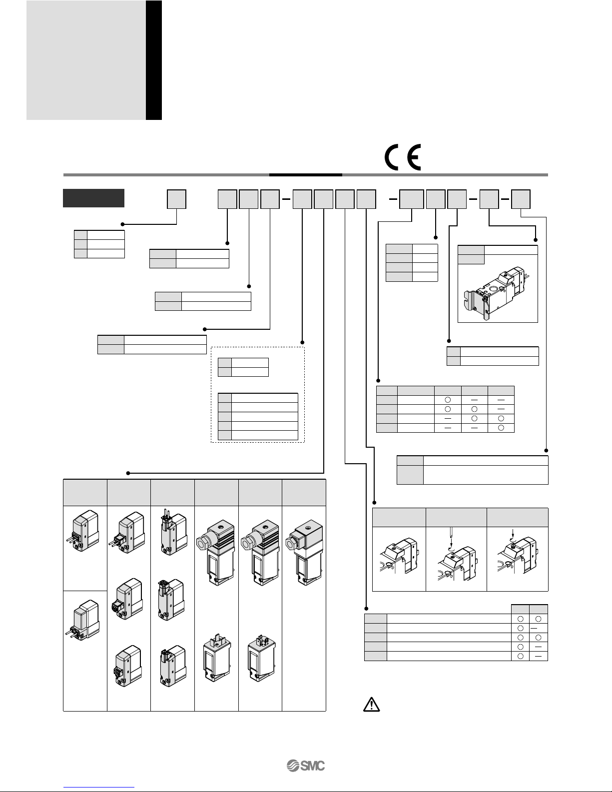
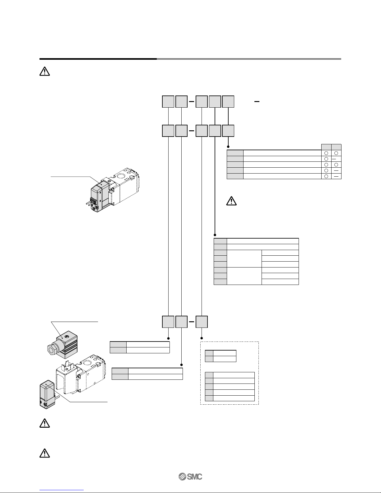
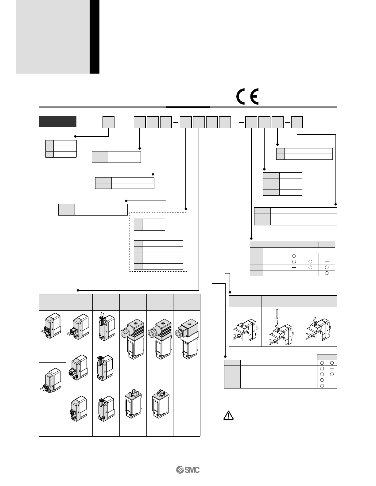
How to Order
Series VP300/500/700
Rubber Seal
3 Port/Pilot Poppet Type
Body Ported/Single Unit
VP
3
4 2
5 G
1
01 A
Series
3
5
7
VP300
VP500
VP700
5
6
24 VDC
12 VDC
Pilot type
—
R
Internal pilot
External pilot
Bracket
—
F
Without bracket
With bracket
Thread type
—
F
N
T
Rc
G
NPT
NPTF
Light/surge voltage suppressor
DC AC
—
S
Z
R
U
Without light/surge voltage suppressor
With surge voltage suppressor
With light/surge voltage suppressor
With surge voltage suppressor (Non-polar)
With light/surge voltage suppressor (Non-polar)
Port size
01
02
03
04
Symbol
Port size
VP300
1/8
1/4
3/8
1/2
VP500
VP700
Manual override
—
: Non-locking
push type
D
:
Push-turn locking
slotted type
E
:
Push-turn locking
lever type
Pressure specification
—
K
Standard (0.7 MPa)
High-pressure type (1.0 MPa)
Electrical entry
Grommet
Conduit
terminal
L-type plug
connector
M-type plug
connector
DIN
terminal
DIN
(EN175301-803)
terminal
G
: Lead wire
length 300 mm
H
: Lead wire
length 600 mm
L
:
With lead wire
(length 300 mm)
LN
:
Without lead wire
LO
:
Without connector
M
:
With lead wire
(length 300 mm)
D
: With connectorY: With connectorT:
Conduit
terminal
DO
:
Without connector
YO
:
Without connector
MN
:
Without lead wire
MO
:
Without connector
G
: Lead wire
length 300 mm
H
: Lead wire
length 600 mm
DC
Without light/
surge voltage
suppressor
Coil specification
—
T
Standard
With power saving circuit (DC only)
Body ported
Note 1) Be sure to select the power sa-
ving circuit type when it is continuously energized for a long time.
(Refer to back page 7 for details.)
Note 2) T type is only available for DC
mode. When T is selected, only
Z type of light/surge voltage
suppressor is available.
(Note that when the electrical
entry of DIN terminal type without connector is selected, only
DOS and YOS are available.)
Note 1) There is no S option for AC mode, since a rectifier prevents
surge voltage generation.
Note 2) In the DIN terminal type, since a light is installed in the con-
nector, DOZ, DOU, YOZ, YOU are not available.
Rated voltage
DC
1
2
3
4
7
100 VAC
200 VAC
110 VAC [115 VAC]
220 VAC [230 VAC]
240 VAC
AC (50/60 Hz)
When using the surge voltage suppressor type,
residual voltage will remain. Refer to back page 7
for details.
Caution
Note 1) LN and MN types are with 2 sockets.
Note 2) Refer to back page 4 when different length of lead wire for L/M-type plug connector is required.
Note 3) Refer to back page 5 for details on the DIN (EN175301-803) terminal.
Note 4) The AC mode of G, H, L and M types are not CE compliant.
[IP65 compatible] [IP65 compatible] [IP65 compatible]
Type of actuation
A
B
N.C. (Normally closed)
N.O. (Normally open)
Made to Order
—
X500
—
Pilot exhaust port with piping thread (M3)
specification (Refer to page 24).
Note) Only DIN and conduit terminal types
are available for AC mode.
Refer to the electrical entry for details.
Note 1)
Note) Only DIN and conduit terminal
types can be set for AC mode. Refer
to the electrical entry for details.
Low power consumption 1.5 W (DC)
Possible to use as either a
selector or divider valve
Possible to change from
N.C. to N.O.
Possible to use in vacuum
applications
Up to –100 kPa
Use external pilot type in the following
cases:
• For vacuum or for low pressure: 0.2 MPa
or less.
• Please consult SMC for use in a vacuum
hold application.
• When having P port downsized in diameter
• When using A port as the atmospheric
releasing port, e.g. air blower.
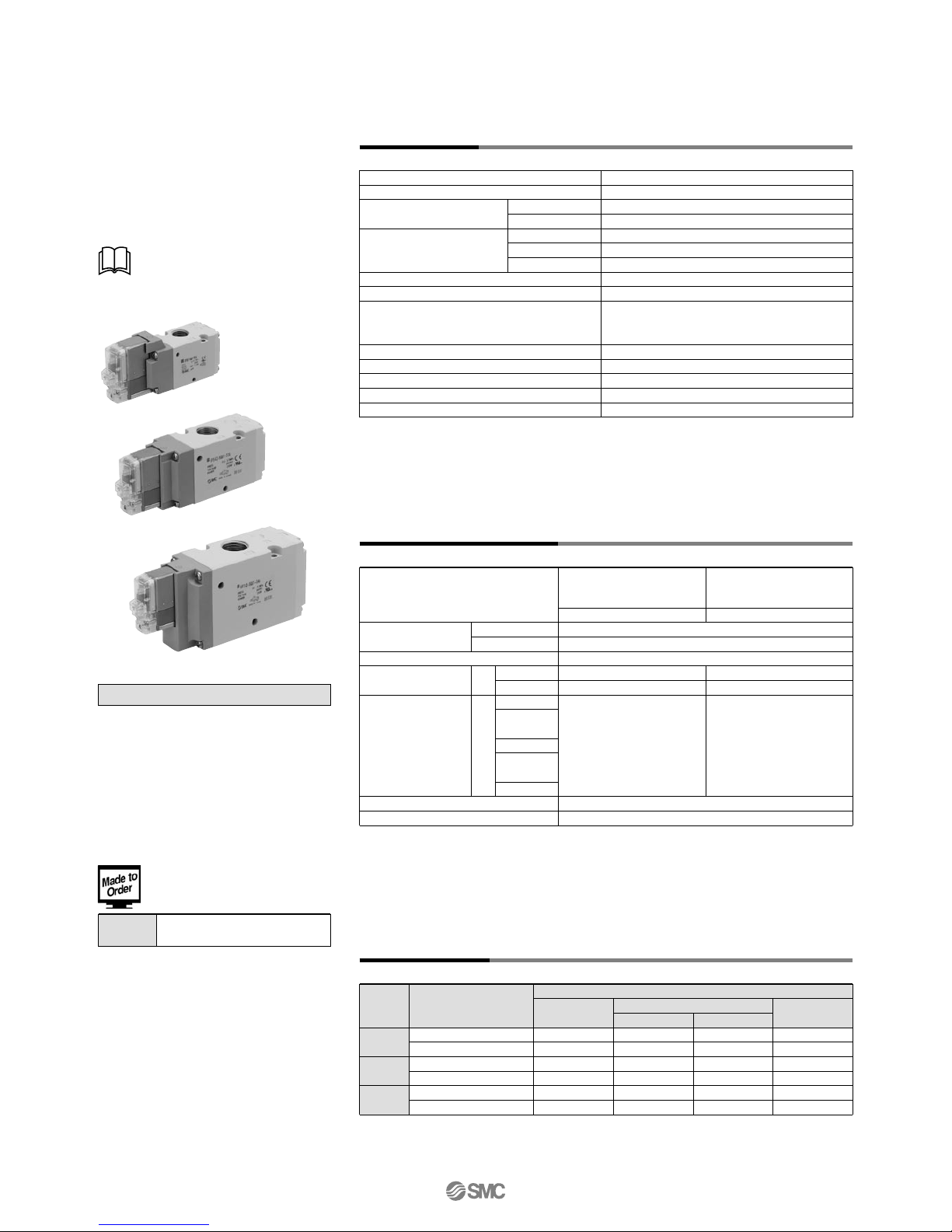
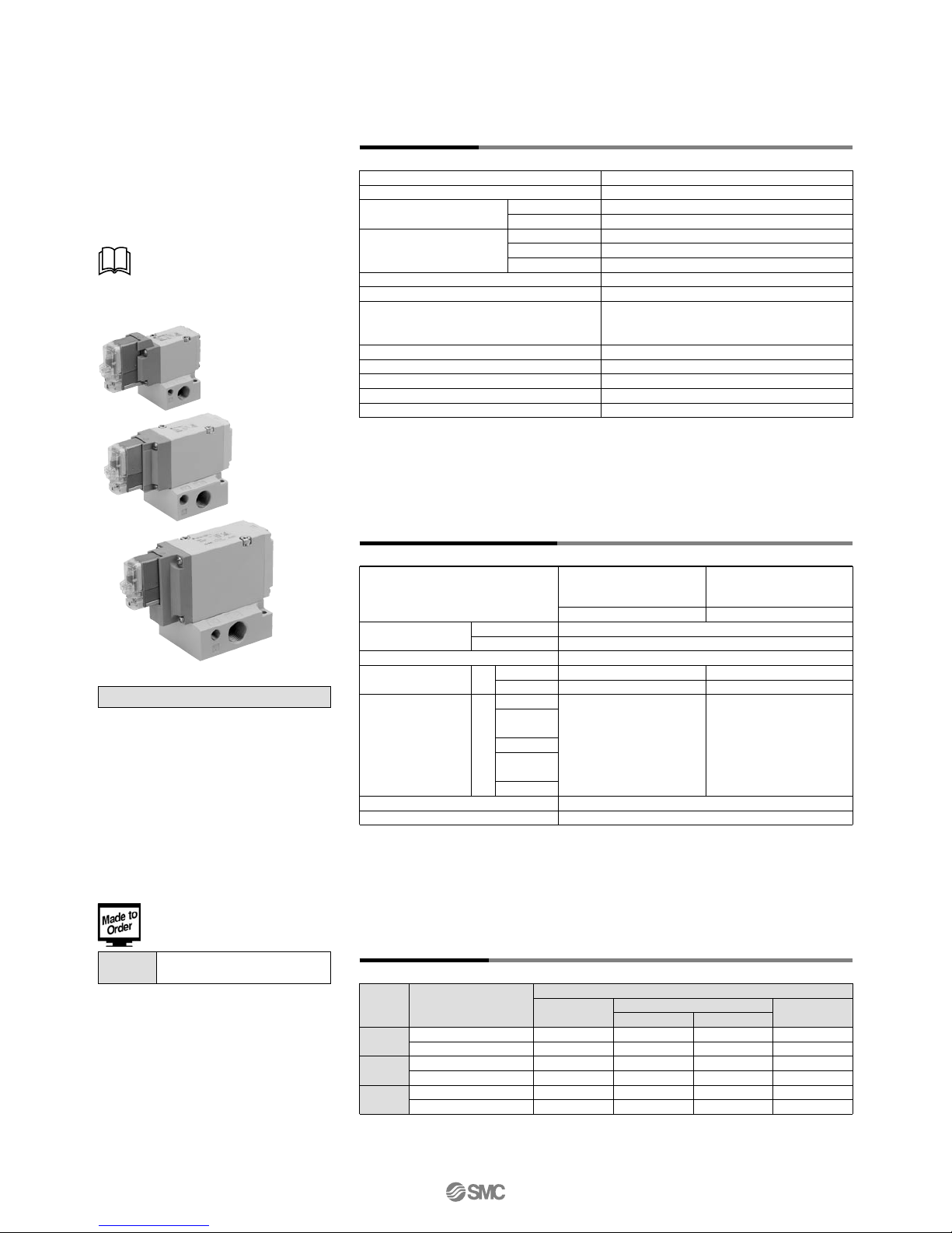
External Pilot
Specifications
Solenoid Specifications
Response Time
Electrical entry
Coil rated voltage (V)
Allowable voltage fluctuation
Power consumption (W)
Apparent power
(VA)
Note 1)
Surge voltage suppressor
Indicator light
24, 12
100, 110, 200, 220, 240
±10% of rated voltage
∗
Diode (Non-polar type: Varistor)
LED (Neon bulb is used for AC mode of D, Y, T.)
1.5 (With light: 1.75)
0.75 (With light only)
1.55 (With light: 1.7)
1.5 (With light: 1.55)
0.55 (With light only)
1.55 (With light: 1.65)
Grommet (G), (H)
L-type plug connector (L)
M-type plug connector (M)
DIN terminal (D)
DIN (EN175301-803) terminal (Y)
Conduit terminal (T)
DC
AC (50/60 Hz)
Standard
With power saving circuit
100 V
110
V
[115 V]
200
V
220
V
[230 V]
240
V
G, H, L, M
D, Y, T
Note 1)
It is in common between 110 VAC and 115 VAC, and between 220 VAC and 230 VAC.
Note 2)
Allowable voltage fluctuation is –15% to +5% of the rated voltage for 115 VAC or 230 VAC.
Note 3)
Since voltage drops due to the internal circuit in S, Z, T types (with power saving circuit), the
allowable voltage fluctuation should be within the following range.
24 VDC: –7% to +10%
12 VDC: –4% to +10%
Fluid
Type of actuation
Internal pilot
Operating pressure range (MPa)
External pilot
Operating pressure range (MPa)
Ambient and fluid temperature (°C)
Max. operating frequency (Hz)
Manual override
Pilot exhaust type
Lubrication
Mounting orientation
Impact/Vibration resistance (m/s
2
)
Note)
Enclosure
Standard
High-pressure type
Standard
High-pressure type
Pilot pressure range
Note) Impact resistance: No malfunction occurred when it is tested in the axial direction and at the right
angles to the main valve and armature in both energized and de-energized states
every once for each condition. (Values at the initial period)
Vibration resistance: No malfunction occurred in a one-sweep test between 45 and 2000 Hz. Test was
performed at both energized and de-energized states in the axial direction and at
the right angles to the main valve and armature. (Values at the initial period)
VP342
VP542
VP742
Standard (0.2 to 0.7)
High-pressure type (0.2 to 1.0)
Standard (0.2 to 0.7)
High-pressure type (0.2 to 1.0)
Standard (0.2 to 0.7)
High-pressure type (0.2 to 1.0)
Response time ms (at 0.5 MPa)
13 or less
17 or less
14 or less
18 or less
19 or less
22 or less
Without light/surge
voltage suppressor
With light/surge voltage suppressor
S, Z type
38 or less
42 or less
39 or less
43 or less
44 or less
47 or less
R, U type
16 or less
20 or less
17 or less
21 or less
22 or less
25 or less
AC
38 or less
42 or less
39 or less
43 or less
44 or less
47 or less
Note) Based on dynamic performance test, JIS B 8375-1981. (Coil temperature: 20°C, at rated voltage)
Pressure specificationsModel
DC
AC
Series VP300
Series VP500
Series VP700
Made to Order
(Refer to page 24 for details.)
Pilot exhaust port with piping
thread (M3) specification
X500
Air
N.C. or N.O. (Convertible)
0.2 to 0.7
0.2 to 1.0
–100 kPa to 0.7
–100 kPa to 1.0
Same as operating pressure (Min. 0.2 MPa)
–10 to 50 (No freezing)
5
Individual exhaust
Not required
Unrestricted
300/50
Dust-tight (IP65 for D, Y, T)
Non-locking push type
Push-turn locking slotted type
Push-turn locking lever type
• Refer to back page 8 for
changing the type of actuation.
Series VP300/500/700
Pilot Poppet Type
Body Ported/Single Unit
1
Low power consumption 1.5 W (DC)
Possible to use as either a
selector or divider valve
Possible to change from
N.C. to N.O.
Possible to use in vacuum
applications
Up to –100 kPa
Use external pilot type in the following
cases:
• For vacuum or for low pressure: 0.2 MPa
or less.
• Please consult SMC for use in a vacuum
hold application.
• When having P port downsized in diameter
• When using A port as the atmospheric
releasing port, e.g. air blower.
External Pilot
Specifications
Solenoid Specifications
Response Time
Electrical entry
Coil rated voltage (V)
Allowable voltage fluctuation
Power consumption (W)
Apparent power
(VA)
Note 1)
Surge voltage suppressor
Indicator light
24, 12
100, 110, 200, 220, 240
±10% of rated voltage
∗
Diode (Non-polar type: Varistor)
LED (Neon bulb is used for AC mode of D, Y, T.)
1.5 (With light: 1.75)
0.75 (With light only)
1.55 (With light: 1.7)
1.5 (With light: 1.55)
0.55 (With light only)
1.55 (With light: 1.65)
Grommet (G), (H)
L-type plug connector (L)
M-type plug connector (M)
DIN terminal (D)
DIN (EN175301-803) terminal (Y)
Conduit terminal (T)
DC
AC (50/60 Hz)
Standard
With power saving circuit
100 V
110
V
[115 V]
200
V
220
V
[230 V]
240
V
G, H, L, M
D, Y, T
Note 1)
It is in common between 110 VAC and 115 VAC, and between 220 VAC and 230 VAC.
Note 2)
Allowable voltage fluctuation is –15% to +5% of the rated voltage for 115 VAC or 230 VAC.
Note 3)
Since voltage drops due to the internal circuit in S, Z, T types (with power saving circuit), the
allowable voltage fluctuation should be within the following range.
24 VDC: –7% to +10%
12 VDC: –4% to +10%
Fluid
Type of actuation
Internal pilot
Operating pressure range (MPa)
External pilot
Operating pressure range (MPa)
Ambient and fluid temperature (°C)
Max. operating frequency (Hz)
Manual override
Pilot exhaust type
Lubrication
Mounting orientation
Impact/Vibration resistance (m/s
2
)
Note)
Enclosure
Standard
High-pressure type
Standard
High-pressure type
Pilot pressure range
Note) Impact resistance: No malfunction occurred when it is tested in the axial direction and at the right
angles to the main valve and armature in both energized and de-energized states
every once for each condition. (Values at the initial period)
Vibration resistance: No malfunction occurred in a one-sweep test between 45 and 2000 Hz. Test was
performed at both energized and de-energized states in the axial direction and at
the right angles to the main valve and armature. (Values at the initial period)
VP342
VP542
VP742
Standard (0.2 to 0.7)
High-pressure type (0.2 to 1.0)
Standard (0.2 to 0.7)
High-pressure type (0.2 to 1.0)
Standard (0.2 to 0.7)
High-pressure type (0.2 to 1.0)
Response time ms (at 0.5 MPa)
13 or less
17 or less
14 or less
18 or less
19 or less
22 or less
Without light/surge
voltage suppressor
With light/surge voltage suppressor
S, Z type
38 or less
42 or less
39 or less
43 or less
44 or less
47 or less
R, U type
16 or less
20 or less
17 or less
21 or less
22 or less
25 or less
AC
38 or less
42 or less
39 or less
43 or less
44 or less
47 or less
Note) Based on dynamic performance test, JIS B 8375-1981. (Coil temperature: 20°C, at rated voltage)
Pressure specificationsModel
DC
AC
Series VP300
Series VP500
Series VP700
Made to Order
(Refer to page 24 for details.)
Pilot exhaust port with piping
thread (M3) specification
X500
Air
N.C. or N.O. (Convertible)
0.2 to 0.7
0.2 to 1.0
–100 kPa to 0.7
–100 kPa to 1.0
Same as operating pressure (Min. 0.2 MPa)
–10 to 50 (No freezing)
5
Individual exhaust
Not required
Unrestricted
300/50
Dust-tight (IP65 for D, Y, T)
Non-locking push type
Push-turn locking slotted type
Push-turn locking lever type
• Refer to back page 8 for
changing the type of actuation.
Series VP300/500/700
Pilot Poppet Type
Body Ported/Single Unit
2
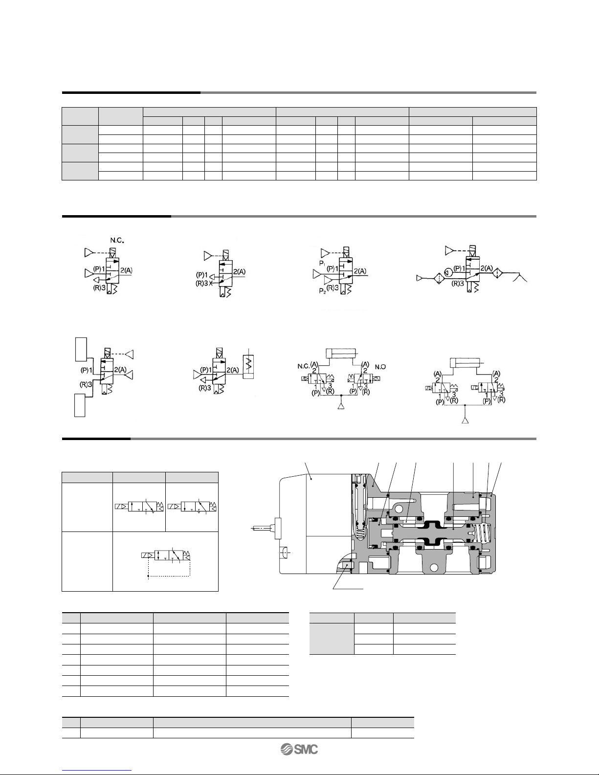
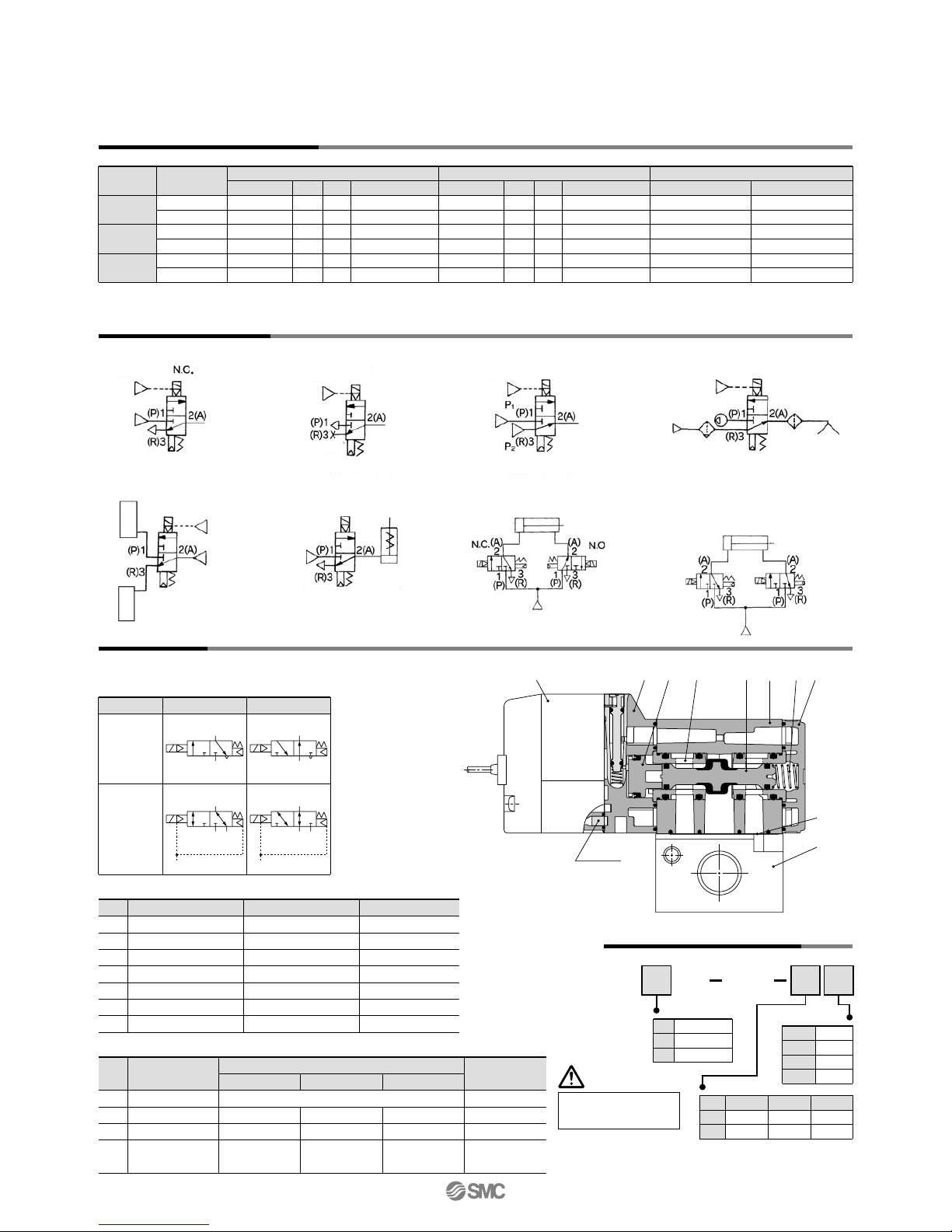
Construction
Application Example
Body
Adapter plate
End plate
Piston
Spool valve
Retainer
Spring
No.
1
2
3
4
5
6
7
Description
Material
Aluminum die-casted
Resin
Resin
Resin
Aluminum/HNBR
Resin
Stainless steel
Note
White
Grey
White
Component Parts
Replacement Parts
DescriptionNo.
Part no.
Refer to “How to Order Pilot Valve Assembly” on page 4.
Pilot valve assembly
Note
Built-in strainer
8
C [dm3/(s·bar)]
b Cv
Mass (g)
Note 1)
Port sizeModel
VP342
VP542
VP742
1/8
1/4
1/4
3/8
3/8
1/2
3.5
4.2
7.9
8.9
11.9
15.1
0.26
0.22
0.21
0.16
0.21
0.21
0.8
1.0
1.8
2.2
2.7
3.6
3.6
4.2
7.2
8.9
11.8
15.3
0.26
0.23
0.27
0.20
0.20
0.22
0.9
1.0
1.8
2.1
2.7
3.7
149
145
249
241
484
467
185
181
285
277
520
503
C [dm3/(s·bar)]
b Cv Grommet DIN terminal
1 ↔ 2 (P ↔ A) 2 ↔ 3 (A ↔ R)
Flow Characteristics/Mass
Body ported
Note 1) Values without bracket
Note 2)
These valves have been calculated according to ISO6358 and indicate the flow rate under standard conditions with an inlet pressure of 0.6 MPa (relative pressure) and a pressure drop of 0.1 MPa.
1
(P)3(R)
(A)
2
1
(P)3(R)
(A)
2
X
1
(P)3(R)
(A)
2
Description
Bracket
(With 2 screws)
Part no.Model
VP342
VP542
VP742
VP300-227-1A
VP500-227-1A
VP700-227-1A
Bracket Assembly Part No.
JIS symbol
Pilot type
External pilot
Internal pilot
N.C.
N.O.
uy eqtrwi
2(A)
1(P) 3(R)
Strainer
(1) Blow-off valve (2) Pressure release valve (3) Selector valve
(5) Divider valve (7) Double-acting
cylinder drive
(6) Single-acting
cylinder drive
(8) Double-acting
cylinder drive
(Exhaust centre)
(4) Valve for vacuum
External pilot
External pilot
Vacuum releasing air
Atmospheric pressure
or micro pressure
External pilot
External pilot
External pilot
Vacuum pump
Vacuum pad
X port
X port
X port
Tank
Tank
X port
X port
Plug
Q [l/min] (ANR)
Note 2)
Q [l/min] (ANR)
Note 2)
868
1018
1903
2085
2867
3637
893
1023
1797
2132
2826
3707
Series VP300/500/700
V211
Pilot valve assembly
DIN connector
(Refer to back page 5.)
V212
Pilot valve assembly
How to Order Pilot Valve Assembly
When only the pilot valve assembly is replaced, it is not possible to change from V211 (Grommet or L/M-type) to V212 (DIN or Conduit
type), or vice versa.
Caution
For V212 (DIN or Conduit type), the coil specification and voltage (including light/surge voltage suppressor) cannot be changed by
changing the pilot valve assembly.
Caution
Tightening torque of the pilot valve assembly mounting screw
M2.5: 0.32 N·m
Caution
VP 1
Valve model:
5 G Z
5
6
24 VDC
12 VDC
Light/surge voltage suppressor
DC AC
—
S
Z
R
U
Without light/surge voltage suppressor
With surge voltage suppressor
With light/surge voltage suppressor
With surge voltage suppressor (Non-polar)
With light/surge voltage suppressor (Non-polar)
Pressure specification
—
K
Standard (0.7 MPa)
High-pressure type (1.0 MPa)
G
H
L
LN
LO
M
MN
MO
Grommet (Lead wire length 300 mm)
Grommet (Lead wire length 600 mm)
With lead wire
Without lead wire
Without connector
With lead wire
Without lead wire
Without connector
Electrical entry
Coil specification
—
T
Standard
With power saving circuit (DC only)
Note) T type is only available for DC mode.
Note) There is no S option for AC mode, since a rectifier prevents
surge voltage generation. When T is selected, only Z type of
light/surge voltage suppressor is available.
Note 1) LN and MN types are with 2 sockets.
Note 2) Refer to back page 4 when different length
of lead wire for L/M-type plug connector is
required.
Rated voltage
DC
1
2
3
4
7
100 VAC
200 VAC
110 VAC [115 VAC]
220 VAC [230 VAC]
240 VAC
AC (50/60 Hz)
When using the surge voltage suppressor type,
residual voltage will remain. Refer to back page 7
for details.
Caution
L-type plug
connector
M-type plug
connector
Grommet or L/M-type
DIN or Conduit type
5 G Z
5
2V
1
1
2V
1
2
Note) Select from the below in accordance with the valve used.
Note)
Series VP300/500/700
Pilot Poppet Type
Body Ported/Single Unit
3
V211
Pilot valve assembly
DIN connector
(Refer to back page 5.)
V212
Pilot valve assembly
How to Order Pilot Valve Assembly
When only the pilot valve assembly is replaced, it is not possible to change from V211 (Grommet or L/M-type) to V212 (DIN or Conduit
type), or vice versa.
Caution
For V212 (DIN or Conduit type), the coil specification and voltage (including light/surge voltage suppressor) cannot be changed by
changing the pilot valve assembly.
Caution
Tightening torque of the pilot valve assembly mounting screw
M2.5: 0.32 N·m
Caution
VP 1
Valve model:
5 G Z
5
6
24 VDC
12 VDC
Light/surge voltage suppressor
DC AC
—
S
Z
R
U
Without light/surge voltage suppressor
With surge voltage suppressor
With light/surge voltage suppressor
With surge voltage suppressor (Non-polar)
With light/surge voltage suppressor (Non-polar)
Pressure specification
—
K
Standard (0.7 MPa)
High-pressure type (1.0 MPa)
G
H
L
LN
LO
M
MN
MO
Grommet (Lead wire length 300 mm)
Grommet (Lead wire length 600 mm)
With lead wire
Without lead wire
Without connector
With lead wire
Without lead wire
Without connector
Electrical entry
Coil specification
—
T
Standard
With power saving circuit (DC only)
Note) T type is only available for DC mode.
Note) There is no S option for AC mode, since a rectifier prevents
surge voltage generation. When T is selected, only Z type of
light/surge voltage suppressor is available.
Note 1) LN and MN types are with 2 sockets.
Note 2) Refer to back page 4 when different length
of lead wire for L/M-type plug connector is
required.
Rated voltage
DC
1
2
3
4
7
100 VAC
200 VAC
110 VAC [115 VAC]
220 VAC [230 VAC]
240 VAC
AC (50/60 Hz)
When using the surge voltage suppressor type,
residual voltage will remain. Refer to back page 7
for details.
Caution
L-type plug
connector
M-type plug
connector
Grommet or L/M-type
DIN or Conduit type
5 G Z
5
2V
1
1
2V
1
2
Note) Select from the below in accordance with the valve used.
Note)
Series VP300/500/700
Pilot Poppet Type
Body Ported/Single Unit
4
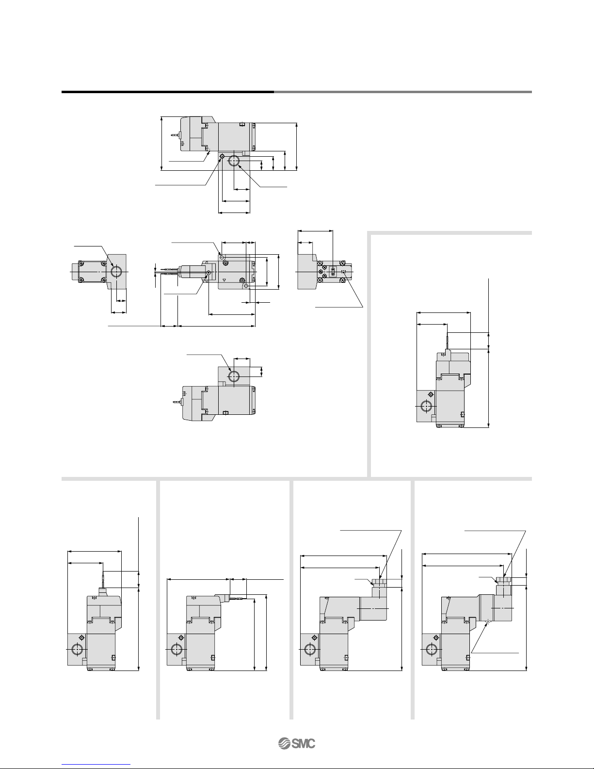
Approx. 300
(Lead wire length)
14
97.3
42.7
96.1
Approx. 300
(Lead wire length)
3.4
(1.6)
1.3
21.5
0.8
(9)
20.4
16
57.6
26.2
11
M5 x 0.8
External pilot port
(External pilot specification: R)
1/8, 1/4
2(A) port
2 x ø3.2
(For mounting)
Manual override
X
2A
NC
25
2.8
15 26.2
42.7
35
31
2 x ø3.2
(For mounting)
Max. 10
82.7
73.7
102.9
Pg9
Applicable cable O.D.
ø4.5 to ø7
Approx. 300
(Lead wire length)
53.7
94
88.9
20
42.7
Approx. 300
(Lead wire length)
102.4
(17.5)
(45)
(54.5)
(5.4)
(35)
19.7
(Indicator light)
+–
(Mounting groove
for M5 thread)
56.4
20.4
16
1.1
26.5
4.5
ø3.8
PE port
Note)
1/8, 1/4
1(P), 3(R) port
NO
3R
1P
(20.9)
(Distance between ports)
Max. 10115.3
86.9 [76.9]
76.9 [66.9]
(Indicator light)
Pg9
Applicable cable O.D.
ø4.5 to ø7
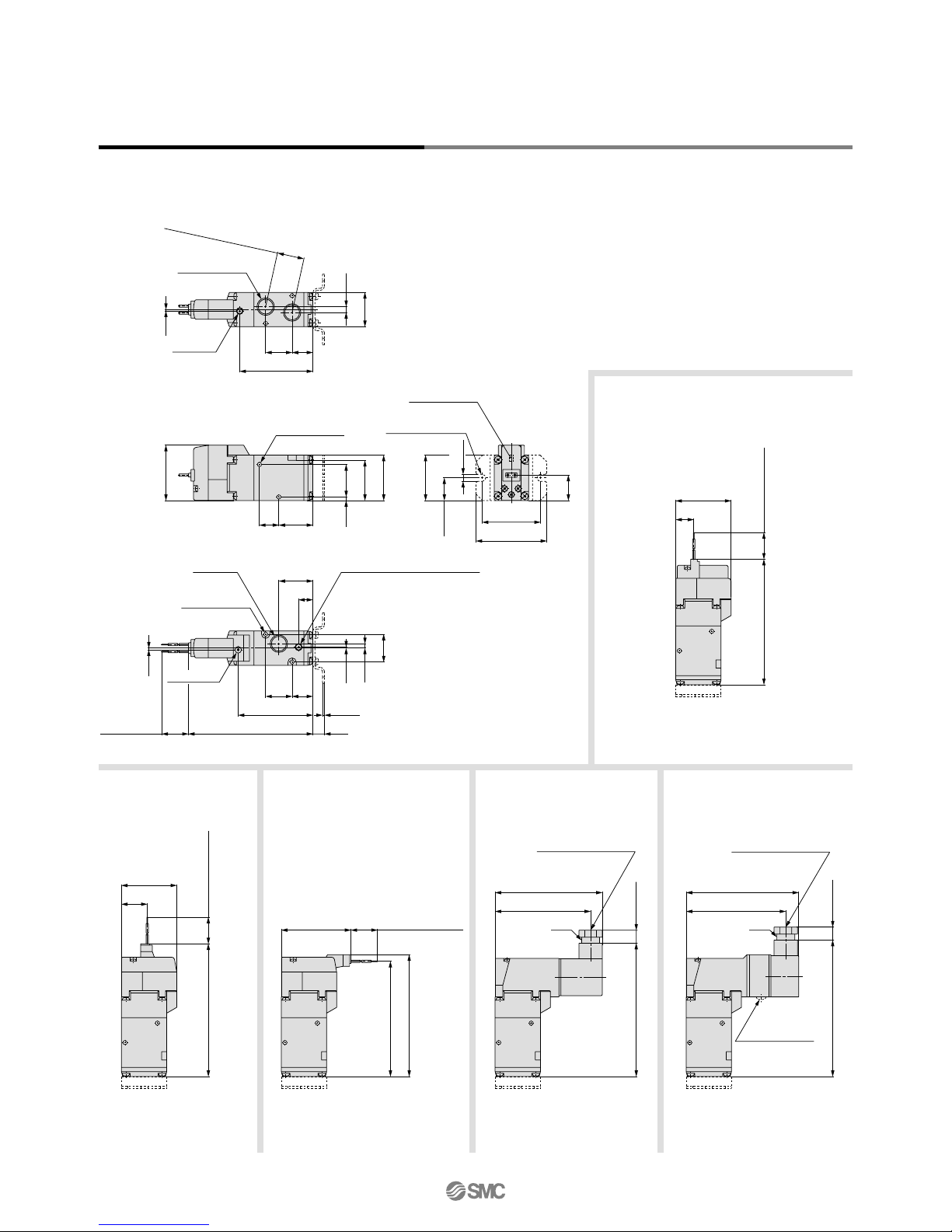
Series VP300/Body Ported/Dimensions
Grommet (G)
Grommet (G)
DC without light/surge voltage suppressor
DIN terminal (D, Y)M-type
plug connector (M)
L-type
plug connector (L)
Conduit terminal (T)
Unless otherwise indicated, dimensions are the same as Grommet (G).
[ ] valves: Without indicator light
Note) Refer to page 24 when piping to PE
port is required.
Series VP300/500/700
16.3
Approx. 300
(Lead wire length)
123.5
45
Max. 10
85
76
129.1
Applicable cable O.D.
ø4.5 to ø7
Pg9
120.2
115.1
Approx. 300
(Lead wire length)
56
Approx. 300
(Lead wire length)
128.6
45
22.3
122.3
Approx. 300
(Lead wire length)
26
4.5
3.5
(1.6)
(9)
83.8
31 25.6
41.1
19
1.3
1/8
External pilot port
(External pilot specification: R)
Manual override
2 x ø4.2
(For mounting)
1/4, 3/8
2(A) port
NC
X
2A
31.5
23.5 39.6
4
40
45
2 x ø4.2
(For mounting)
2.5
32
7
83.6
30.7 25.6
1/4, 3/8
1(P), 3(R) port
ø3.8
PE port
Note)
NO
1P 3R
(31.5)
(Distance between ports)
89.2 [79.2]
79.2 [69.2]
Max. 10131.5
Pg9
(Indicator light)
Applicable cable O.D.
ø4.5 to ø7
Note) Refer to page 24 when piping
to PE port is required.
(22.5)
(60)
(50)
(5.4)
(45)
22
(Indicator light)
+–
(Mounting groove
for M5 thread)
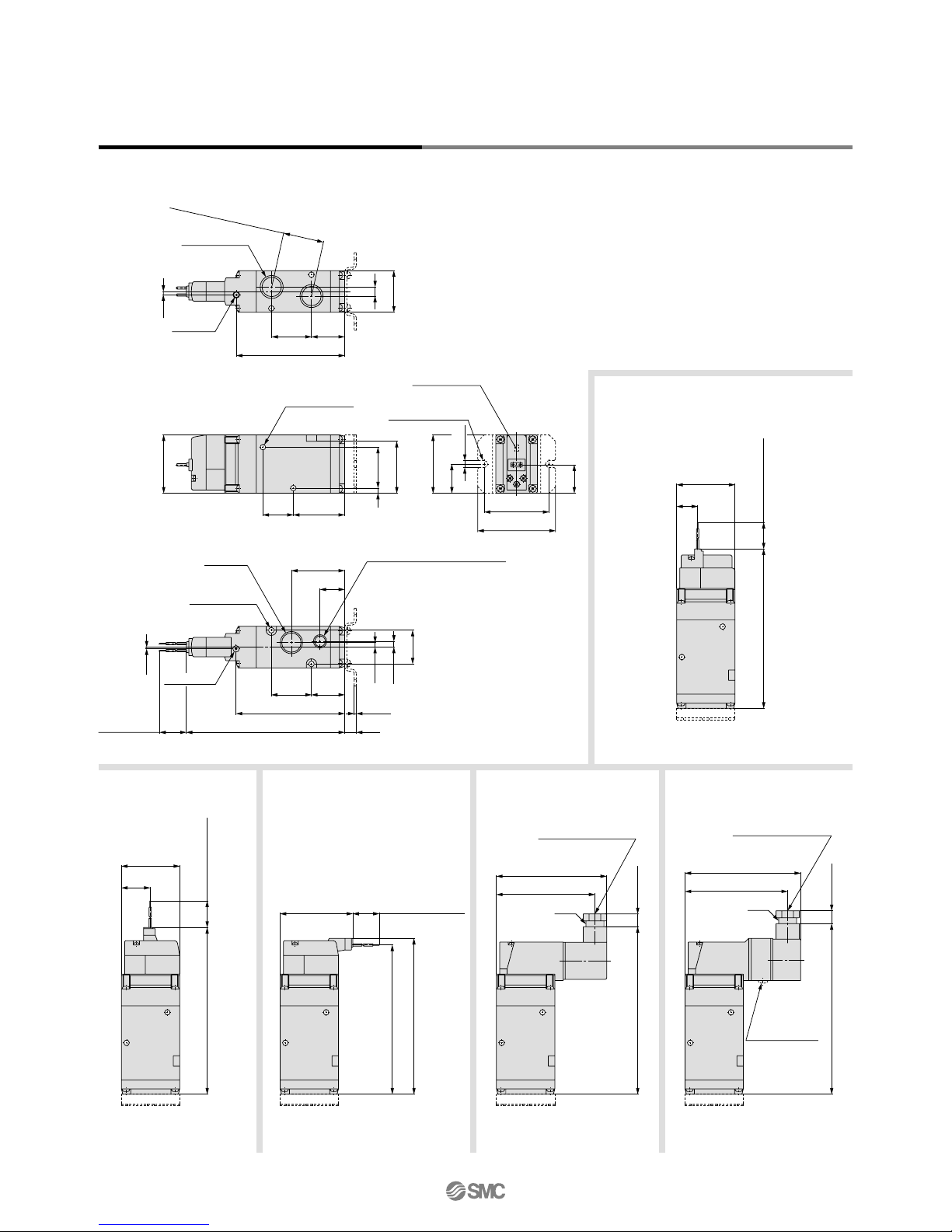
Series VP500/Body Ported/Dimensions
Grommet (G)
DC without light/surge voltage suppressor
Unless otherwise indicated, dimensions are the same as Grommet (G).
[ ] valves: Without indicator light
Grommet (G)
DIN terminal (D, Y)
M-type
plug connector (M)
L-type
plug connector (L)
Conduit terminal (T)
Series VP300/500/700
Pilot Poppet Type
Body Ported/Single Unit
5
16.3
Approx. 300
(Lead wire length)
123.5
45
Max. 10
85
76
129.1
Applicable cable O.D.
ø4.5 to ø7
Pg9
120.2
115.1
Approx. 300
(Lead wire length)
56
Approx. 300
(Lead wire length)
128.6
45
22.3
122.3
Approx. 300
(Lead wire length)
26
4.5
3.5
(1.6)
(9)
83.8
31 25.6
41.1
19
1.3
1/8
External pilot port
(External pilot specification: R)
Manual override
2 x ø4.2
(For mounting)
1/4, 3/8
2(A) port
NC
X
2A
31.5
23.5 39.6
4
40
45
2 x ø4.2
(For mounting)
2.5
32
7
83.6
30.7 25.6
1/4, 3/8
1(P), 3(R) port
ø3.8
PE port
Note)
NO
1P 3R
(31.5)
(Distance between ports)
89.2 [79.2]
79.2 [69.2]
Max. 10131.5
Pg9
(Indicator light)
Applicable cable O.D.
ø4.5 to ø7
Note) Refer to page 24 when piping
to PE port is required.
(22.5)
(60)
(50)
(5.4)
(45)
22
(Indicator light)
+–
(Mounting groove
for M5 thread)
Series VP500/Body Ported/Dimensions
Grommet (G)
DC without light/surge voltage suppressor
Unless otherwise indicated, dimensions are the same as Grommet (G).
[ ] valves: Without indicator light
Grommet (G)
DIN terminal (D, Y)
M-type
plug connector (M)
L-type
plug connector (L)
Conduit terminal (T)
Series VP300/500/700
Pilot Poppet Type
Body Ported/Single Unit
6
34.3
Approx. 300
(Lead wire length)
146.5
63
Max. 10
152.1
94
103
Pg9
Applicable cable O.D.
ø4.5 to ø7
138.1
143.2
Approx. 300
(Lead wire length)
74
Approx. 300
(Lead wire
length)
151.6
63
40.3
145.3
Approx. 300
(Lead wire length)
(2)
106.8
(9)
51.5
27.5
41 31
33
7.5
4.5
1.3
1/8
External pilot port
(External pilot specification: R)
3/8, 1/2
2(A) port
2 x ø5.2
(For mounting)
Manual override
NC
X
2A
38.5
9.4
31 51.5
56.5
63
2 x ø5.2
(For mounting)
107.2 [97.2]
97.2 [87.2]
Max. 10154.5
Pg9
(Indicator light)
Applicable cable O.D.
ø4.5 to ø7
Note) Refer to page 24 when piping to
PE port is required.
40
(31.5)
(60)
(74)
(6.4)
(63)
(Indicator light)
+–
(Mounting
groove for
M6 thread)
107.5
42 30.5
40
9
2.5
ø4
PE port
Note)
3/8, 1/2
1(P), 3(R) port
NO
3R1P
(43)
(Distance between ports)
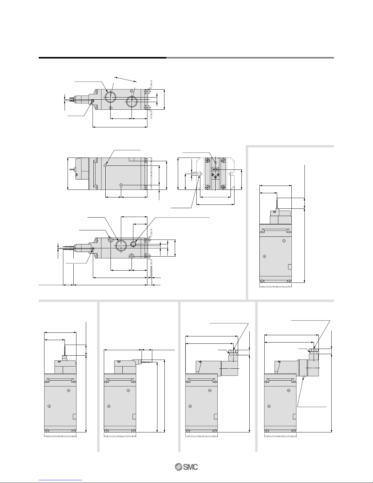
Grommet (G)
DC without light/surge
voltage suppressor
Unless otherwise indicated, dimensions are the same as Grommet (G).
[ ] valves: Without indicator light
Series VP700/Body Ported/Dimensions
Grommet (G)
DIN terminal (D, Y)
M-type
plug connector (M)
L-type
plug connector (L)
Conduit terminal (T)
Series VP300/500/700
7
VP
3
4 4
5 G
1
A
3
5
7
VP300
VP500
VP700
Type of actuation
A
B
N.C. (Normally closed)
N.O. (Normally open)
5
6
24 VDC
12 VDC
Pilot type
—
R
Thread type
—
F
N
T
Rc
G
NPT
NPTF
Light/surge voltage suppressor
DC AC
—
S
Z
R
U
Without light/surge voltage suppressor
With surge voltage suppressor
With light/surge voltage suppressor
With surge voltage suppressor (Non-polar)
With light/surge voltage suppressor (Non-polar)
Port size (Sub-plate)
01
02
03
04
Symbol
—
Port size
VP300
Without sub-plate
∗
1/8
1/4
3/8
1/2
VP500 VP700
Manual override
Pressure specification
—
K
Standard (0.7 MPa)
High-pressure type (1.0 MPa)
Electrical entry
Coil specification
—
T
Standard
With power saving circuit (DC only)
Note 1) Be sure to select the power
saving circuit type when it is
continuously energized for a long
time. (Refer to back page 7 for
details.)
Note 2) T type is only available for DC
mode. When T is selected, only Z
type of light/surge voltage
suppressor is available.
(Note that when the electrical
entry of DIN terminal type without
connector is selected, only DOS
and YOS are available.)
Note 1) There is no S option for AC mode, since a rectifier prevents
surge voltage generation.
Note 2) In the DIN terminal type, since a light is installed in the con-
nector, DOZ, DOU, YOZ, YOU are not available.
Note) With a gasket and two mounting bolts.
Rated voltage
DC
1
2
3
4
7
100 VAC
200 VAC
110 VAC [115 VAC]
220 VAC [230 VAC]
240 VAC
AC (50/60 Hz)
When using the surge voltage suppressor type,
residual voltage will remain. Refer to back page 7
for details.
Caution
Note 1) LN and MN types are with 2 sockets.
Note 2) Refer to back page 4 when different length of lead wire for L/M-type plug connector is required.
Note 3) Refer to back page 5 for details on the DIN (EN175301-803) terminal.
Note 4) The AC mode of G, H, L and M types are not CE compliant.
Made to Order
—
X500
Pilot exhaust port with piping thread
(M3) specification (Refer to page 24).
[IP65 compatible] [IP65 compatible] [IP65 compatible]
Series VP300/500/700
Rubber Seal
3 Port/Pilot Poppet Type
Base Mounted/Single Unit
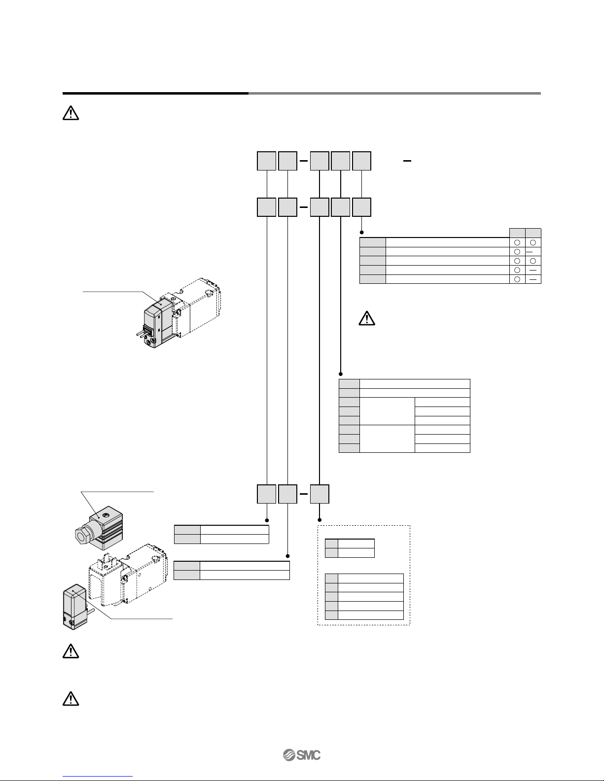
How to Order
Base mounted
Series
Internal pilot
External pilot
Grommet
Conduit
terminal
L-type plug
connector
M-type plug
connector
DIN
terminal
DIN
(EN175301-803)
terminal
G
: Lead wire
length 300 mm
H
: Lead wire
length 600 mm
L
:
With lead wire
(length 300 mm)
LN
:
Without lead wire
LO
:
Without connector
M
:
With lead wire
(length 300 mm)
D
: With connectorY: With connectorT:
Conduit
terminal
DO
:
Without connector
YO
:
Without connector
MN
:
Without lead wire
MO
:
Without connector
G
: Lead wire
length 300 mm
H
: Lead wire
length 600 mm
DC
Without light/
surge voltage
suppressor
—
: Non-locking
push type
D
: Push-turn locking
slotted type
E
: Push-turn locking
lever type
Note 1)
Note) Only DIN and conduit terminal types
are available for AC mode.
Refer to the electrical entry for details.
Note) Only DIN and conduit terminal
types can be set for AC mode. Refer
to the electrical entry for details.
8
Use external pilot type in the following
cases:
• For vacuum or for low pressure 0.2 MPa or
less
• Please consult with SMC for use in a
vacuum hold application.
• When having P port downsized in diameter
• When using A port as the atmospheric
releasing port, e.g. air blower
• If manifold, external pilot piping can be
centralized in manifold base.
External Pilot
VP344
VP544
VP744
Note) Based on dynamic performance test, JIS B 8375-1981. (Coil temperature: 20°C, at rated voltage)
Pressure specifications
Note 1) It is in common between 110 VAC and 115 VAC, and between 220 VAC and 230 VAC.
Note 2) Allowable voltage fluctuation is –15% to +5% of the rated voltage for 115 VAC or 230 VAC.
Note 3) Since voltage drops due to the internal circuit in S, Z, T types (with power saving circuit), the
allowable voltage fluctuation should be within the following range.
24 VDC: –7% to +10%
12 VDC: –4% to +10%
Series VP300
Series VP500
Series VP700
Made to Order
(Refer to page 24 for details.)
Pilot exhaust port with piping
thread (M3) specification
X500
Low power consumption 1.5 W (DC)
Possible to use as either a
selector or divider valve
Possible to change from
N.C. to N.O.
Possible to use in vacuum
applications
Up to –100 kPa
• Refer to back page 8 for
changing the type of actuation.
Note) Impact resistance: No malfunction occurred when tested in both the axial and right angle directions
of main valve and armature (tested in both energized and de-energized states).
(Values at the initial period).
Vibration resistance: No malfunction occurred when tested in a one-sweep test between 45 and 2000
Hz, in both the axial and right angle directions of main valve and armature (tested
in both energized and de-energized states). (Values at the initial period).
Fluid
Type of actuation
Internal pilot
Operating pressure range (MPa)
External pilot
Operating pressure range (MPa)
Ambient and fluid temperature (°C)
Max. operating frequency (Hz)
Manual override
Pilot exhaust type
Lubrication
Mounting orientation
Impact/Vibration resistance (m/s
2
)
Note)
Enclosure
Standard
High-pressure type
Standard
High-pressure type
Pilot pressure range
Air
N.C. or N.O. (Convertible)
0.2 to 0.7
0.2 to 1.0
–100 kPa to 0.7
–100 kPa to 1.0
Same as operating pressure (Min. 0.2 MPa)
–10 to 50 (No freezing)
5
Individual exhaust
Not required
Unrestricted
300/50
Dust-tight (IP65 for D, Y, T)
Non-locking push type
Push-turn locking slotted type
Push-turn locking lever type
Specifications
Electrical entry
Coil rated voltage (V)
Allowable voltage fluctuation
Power consumption (W)
Apparent power
(VA)
Notes)
Surge voltage suppressor
Indicator light
24, 12
100, 110, 200, 220, 240
±10% of rated voltage
Notes)
Diode (Non-polar type: Varistor)
LED (Neon bulb is used for AC mode of D, Y, T.)
1.5 (With light: 1.75)
0.75 (With light only)
1.55 (With light: 1.7)
1.5 (With light: 1.55)
0.55 (With light only)
1.55 (With light: 1.65)
Grommet (G), (H)
L-type plug connector (L)
M-type plug connector (M)
DIN terminal (D)
DIN (EN175301-803) terminal (Y)
Conduit terminal (T)
DC
AC (50/60 Hz)
Standard
With power saving circuit
100 V
110 V
[115 V]
200
V
220
V
[230 V]
240
V
G, H, L, M
D, Y, T
DC
AC
Solenoid Specifications
Response Time
Standard (0.2 to 0.7)
High-pressure type (0.2 to 1.0)
Standard (0.2 to 0.7)
High-pressure type (0.2 to 1.0)
Standard (0.2 to 0.7)
High-pressure type (0.2 to 1.0)
Response time ms (at 0.5 MPa)
13 or less
17 or less
14 or less
18 or less
19 or less
22 or less
Without light/surge
voltage suppressor
With light/surge voltage suppressor
S, Z type
38 or less
42 or less
39 or less
43 or less
44 or less
47 or less
R, U type
16 or less
20 or less
17 or less
21 or less
22 or less
25 or less
AC
38 or less
42 or less
39 or less
43 or less
44 or less
47 or less
Model
Series VP300/500/700
Construction
Application Example
Body
Adapter plate
End plate
Piston
Spool valve
Retainer
Spring
No.
1
2
3
4
5
6
7
Description Material
Aluminum die-casted
Resin
Resin
Resin
Aluminum/HNBR
Resin
Stainless steel
Note
White
Grey
White
Component Parts
Replacement Parts
DescriptionNo.
Part no.
VP544
Refer to “How to Order Pilot Valve Assembly” on page 11.
VP500-217-1
VP500-202-
VP500-224-1
(M4 x 46)
VP744
VP700-217-1
VP700-202-
VP700-224-1
(M5 x 66)
VP344
VP300-217-1
VP300-202-
VP300-224-1
(M3 x 36)
Pilot valve assembly
Gasket
Sub-plate
Hexagon socket
head bolt (1 pc.)
Note
Built-in strainer
HNBR
Aluminum die-casted
For valve mounting
8
9
10
—
Caution
Tightening Torque
of Mounting Screw
M3: 0.8 N·m
M4: 1.4 N·m
M5: 2.9 N·m
b Cv
VP344
VP544
VP744
1/8
1/4
1/4
3/8
3/8
1/2
b C
v
Base mounted
VP
Port size
Thread type
Series
3 1
How to Order Sub-plate
3
5
7
VP344
VP544
VP744
Nil
F
N
T
Rc
G
NPT
NPTF
Symbol
1
2
VP344
1/8
1/4
VP544
1/4
3/8
VP744
3/8
1/2
20200
3.6
3.9
7.5
8.8
12.9
14.7
0.22
0.22
0.16
0.07
0.10
0.05
0.8
0.9
1.7
2.0
2.9
3.3
3.5
3.8
7.3
8.8
13.3
15.0
0.24
0.14
0.20
0.13
0.24
0.17
0.8
0.9
1.7
2.0
3.1
3.4
216 (149)
211 (149)
370 (245)
362 (245)
676 (459)
658 (459)
252 (185)
247 (185)
406 (281)
398 (281)
712 (495)
694 (495)
Note 1) ( ) valves: Values without sub-plate
Note 2)
These valves have been calculated according to ISO6358 and indicate the flow rate under standard conditions with an inlet pressure of 0.6 MPa (relative pressure) and a pressure drop of 0.1 MPa.
JIS symbol
1
(P)3(R)
(A)
2
1
(P)3(R)
(A)
2
1
(P)3(R)
(A)
2
X
1
(P)3(R)
(A)
2
Pilot type
External
pilot
Internal
pilot
N.C. N.O.
X
Strainer
X
uy eqtrwi
o
!0
2(A)
3(R)
1(P)
Flow Characteristics/Mass
C [dm3/(s·bar)]
Mass (g)
Note 1)
Port sizeModel
C [dm3/(s·bar)]
Grommet DIN terminal
1 ↔ 2 (P ↔ A) 2 ↔ 3 (A ↔ R)
(1) Blow-off valve (2) Pressure release valve (3) Selector valve
(5) Divider valve
(7) Double-acting
cylinder drive
(6) Single-acting
cylinder drive
(8) Double-acting
cylinder drive
(Exhaust centre)
(4) Valve for vacuum
External pilot
External pilot
Vacuum releasing air
Atmospheric pressure
or micro pressure
External pilot
External pilot
External pilot
Vacuum pump
Vacuum pad
X port
X port
X port
Tank
Tank
X port
X port
Plug
872
945
1757
1967
2929
3256
858
881
1749
2029
3260
3534
Q [l/min] (ANR)
Note 2)
Q [l/min] (ANR)
Note 2)
Series VP300/500/700
Pilot Poppet Type
Base Mounted/Single Unit
9
Construction
Application Example
Body
Adapter plate
End plate
Piston
Spool valve
Retainer
Spring
No.
1
2
3
4
5
6
7
Description Material
Aluminum die-casted
Resin
Resin
Resin
Aluminum/HNBR
Resin
Stainless steel
Note
White
Grey
White
Component Parts
Replacement Parts
DescriptionNo.
Part no.
VP544
Refer to “How to Order Pilot Valve Assembly” on page 11.
VP500-217-1
VP500-202-
VP500-224-1
(M4 x 46)
VP744
VP700-217-1
VP700-202-
VP700-224-1
(M5 x 66)
VP344
VP300-217-1
VP300-202-
VP300-224-1
(M3 x 36)
Pilot valve assembly
Gasket
Sub-plate
Hexagon socket
head bolt (1 pc.)
Note
Built-in strainer
HNBR
Aluminum die-casted
For valve mounting
8
9
10
—
Caution
Tightening Torque
of Mounting Screw
M3: 0.8 N·m
M4: 1.4 N·m
M5: 2.9 N·m
b Cv
VP344
VP544
VP744
1/8
1/4
1/4
3/8
3/8
1/2
b C
v
Base mounted
VP
Port size
Thread type
Series
3 1
How to Order Sub-plate
3
5
7
VP344
VP544
VP744
Nil
F
N
T
Rc
G
NPT
NPTF
Symbol
1
2
VP344
1/8
1/4
VP544
1/4
3/8
VP744
3/8
1/2
20200
3.6
3.9
7.5
8.8
12.9
14.7
0.22
0.22
0.16
0.07
0.10
0.05
0.8
0.9
1.7
2.0
2.9
3.3
3.5
3.8
7.3
8.8
13.3
15.0
0.24
0.14
0.20
0.13
0.24
0.17
0.8
0.9
1.7
2.0
3.1
3.4
216 (149)
211 (149)
370 (245)
362 (245)
676 (459)
658 (459)
252 (185)
247 (185)
406 (281)
398 (281)
712 (495)
694 (495)
Note 1) ( ) valves: Values without sub-plate
Note 2)
These valves have been calculated according to ISO6358 and indicate the flow rate under standard conditions with an inlet pressure of 0.6 MPa (relative pressure) and a pressure drop of 0.1 MPa.
JIS symbol
1
(P)3(R)
(A)
2
1
(P)3(R)
(A)
2
1
(P)3(R)
(A)
2
X
1
(P)3(R)
(A)
2
Pilot type
External
pilot
Internal
pilot
N.C. N.O.
X
Strainer
X
uy eqtrwi
o
!0
2(A)
3(R)
1(P)
Flow Characteristics/Mass
C [dm3/(s·bar)]
Mass (g)
Note 1)
Port sizeModel
C [dm3/(s·bar)]
Grommet DIN terminal
1 ↔ 2 (P ↔ A) 2 ↔ 3 (A ↔ R)
(1) Blow-off valve (2) Pressure release valve (3) Selector valve
(5) Divider valve
(7) Double-acting
cylinder drive
(6) Single-acting
cylinder drive
(8) Double-acting
cylinder drive
(Exhaust centre)
(4) Valve for vacuum
External pilot
External pilot
Vacuum releasing air
Atmospheric pressure
or micro pressure
External pilot
External pilot
External pilot
Vacuum pump
Vacuum pad
X port
X port
X port
Tank
Tank
X port
X port
Plug
872
945
1757
1967
2929
3256
858
881
1749
2029
3260
3534
Q [l/min] (ANR)
Note 2)
Q [l/min] (ANR)
Note 2)
Series VP300/500/700
Pilot Poppet Type
Base Mounted/Single Unit
10
V211
Pilot valve assembly
DIN connector
(Refer to back page 5.)
V212
Pilot valve assembly
How to Order Pilot Valve Assembly
When only the pilot valve assembly is replaced, it is not possible to change from V211 (Grommet or L/M-type) to V212 (DIN or Conduit
type), or vice versa.
Caution
For V212 (DIN or Conduit type), the coil specification and voltage (including light/surge voltage suppressor) cannot be changed by
changing the pilot valve assembly.
Caution
Tightening torque of the pilot valve assembly mounting screw
M2.5: 0.32 N·m
Caution
VP 1
5 G
Z
5
6
24 VDC
12 VDC
Light/surge voltage suppressor
DC AC
—
S
Z
R
U
Without light/surge voltage suppressor
With surge voltage suppressor
With light/surge voltage suppressor
With surge voltage suppressor (Non-polar)
With light/surge voltage suppressor (Non-polar)
Pressure specification
—
K
Standard (0.7 MPa)
High-pressure type (1.0 MPa)
G
H
L
LN
LO
M
MN
MO
Grommet (Lead wire length 300 mm)
Grommet (Lead wire length 600 mm)
With lead wire
Without lead wire
Without connector
With lead wire
Without lead wire
Without connector
Electrical entry
Coil specification
—
T
Standard
With power saving circuit (DC only)
Note) T type is only available for DC mode.
Note) There is no S option for AC mode, since a rectifier prevents
surge voltage generation. When T is selected, only Z type of
light/surge voltage suppressor is available.
Rated voltage
DC
1
2
3
4
7
100 VAC
200 VAC
110 VAC [115 VAC]
220 VAC [230 VAC]
240 VAC
AC (50/60 Hz)
When using the surge voltage suppressor type,
residual voltage will remain. Refer to back page 7
for details.
Caution
L-type plug
connector
M-type plug
connector
DIN or Conduit type
5 G Z
5
2V
1
1
2V
1
2
Note) Select from the below in accordance with the valve used.
Note 1) LN and MN types are with 2 sockets.
Note 2) Refer to back page 4 when different
length of lead wire for L/M-type plug
connector is required.
Valve model:
Grommet or L/M-type
Note)
Series VP300/500/700
Approx. 300
(Lead wire length)
97.3
66.7
38
X
Max. 10
102.9
106.7
97.7
Applicable cable O.D.
ø4.5 to ø7
Pg9
X
Approx. 300
(Lead wire length)
77.7
94
88.9
X
102.4
Approx. 300
(Lead wire length)
66.7
44
X
39
34
19.5
66.7
24
59
17.5
12
1/8, 1/4
1(P) port
M5 x 0.8
External pilot port
PE port
Note)
(ø3.8)
X
19.5
12
1/8, 1/4
2(A) port
1.3
96.1
35
Approx. 300
(Lead wire length)
43
57.6
6.7
11.230
2 x ø4.2
(For mounting)
Manual override
2ANO
1PNC
NC
18.5
12
1/8, 1/4
3(R) port
3R
43.7
18.5
(Indicator light)
+
–
110.9 [100.9]
100.9 [90.9]
Max. 10105.3
Pg9
(Indicator light)
Applicable cable O.D.
ø4.5 to ø7
X
Note) Refer to page 24 when piping to PE port is
required.
Series VP300/Base Mounted/Dimensions
Grommet (G)
Grommet (G)
DC without light/surge voltage suppressor
DIN terminal (D, Y)M-type
plug connector (M)
L-type
plug connector (L)
Conduit terminal (T)
Unless otherwise indicated, dimensions are the same as Grommet (G).
[ ] valves: Without indicator light
Series VP300/500/700
Pilot Poppet Type
Base Mounted/Single Unit
11
Approx. 300
(Lead wire length)
97.3
66.7
38
X
Max. 10
102.9
106.7
97.7
Applicable cable O.D.
ø4.5 to ø7
Pg9
X
Approx. 300
(Lead wire length)
77.7
94
88.9
X
102.4
Approx. 300
(Lead wire length)
66.7
44
X
39
34
19.5
66.7
24
59
17.5
12
1/8, 1/4
1(P) port
M5 x 0.8
External pilot port
PE port
Note)
(ø3.8)
X
19.5
12
1/8, 1/4
2(A) port
1.3
96.1
35
Approx. 300
(Lead wire length)
43
57.6
6.7
11.230
2 x ø4.2
(For mounting)
Manual override
2ANO
1PNC
NC
18.5
12
1/8, 1/4
3(R) port
3R
43.7
18.5
(Indicator light)
+
–
110.9 [100.9]
100.9 [90.9]
Max. 10105.3
Pg9
(Indicator light)
Applicable cable O.D.
ø4.5 to ø7
X
Note) Refer to page 24 when piping to PE port is
required.
Series VP300/Base Mounted/Dimensions
Grommet (G)
Grommet (G)
DC without light/surge voltage suppressor
DIN terminal (D, Y)M-type
plug connector (M)
L-type
plug connector (L)
Conduit terminal (T)
Unless otherwise indicated, dimensions are the same as Grommet (G).
[ ] valves: Without indicator light
Series VP300/500/700
Pilot Poppet Type
Base Mounted/Single Unit
12
 Loading...