

SMC Networks VP3145, VP3165, VP3185, VP3145-X80, VP3165-X80 Installation And Maintenance Manual
...
2 INTENDED CONDITIONS OF USE
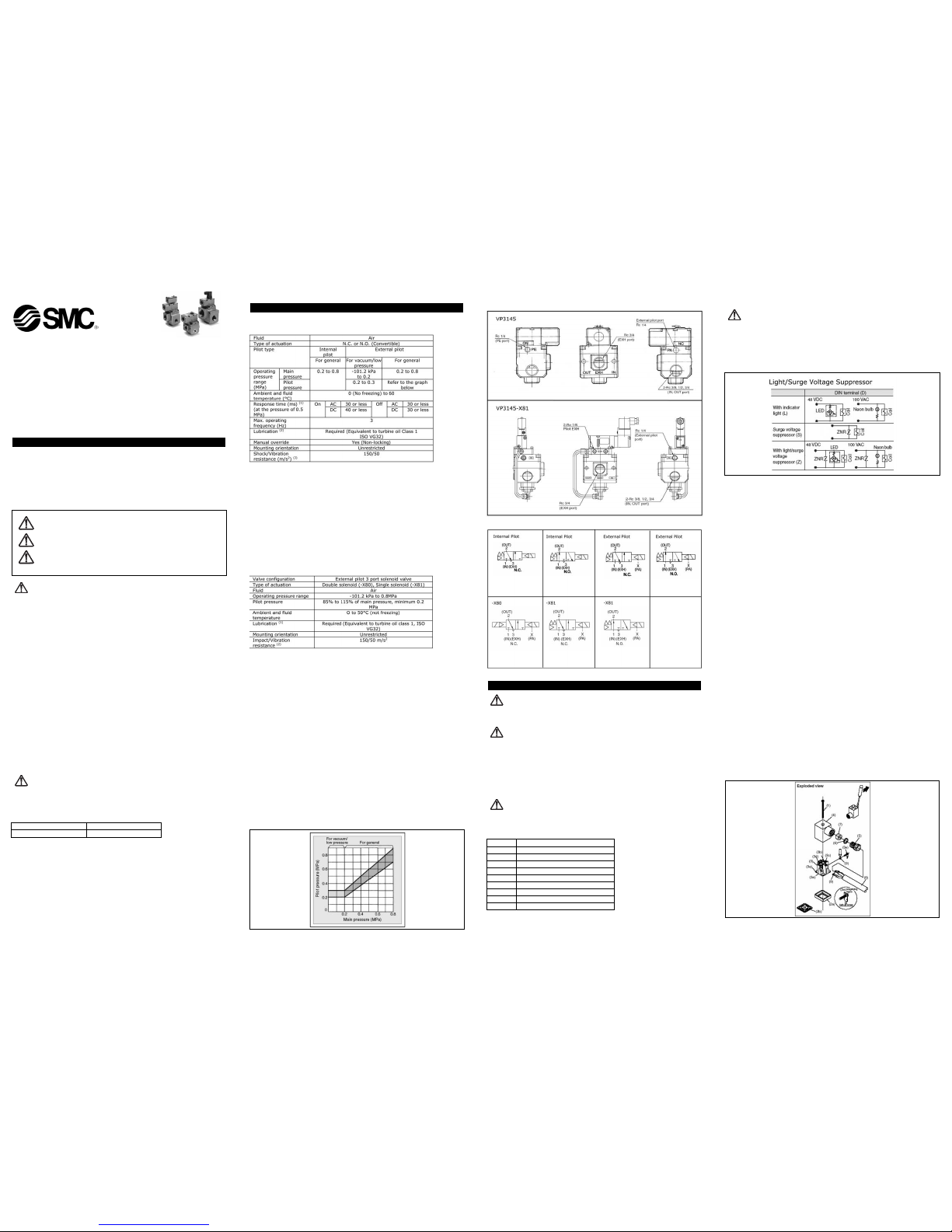
2.1 Specifications
VP3145/3165/3185 Specifications
(Note 1) IBased on dynamic performance test, JIS B 8374-1981. (Coil temperature:
20°C, at rated voltage, without surge voltage suppressor)
(Note 2) This solenoid valve requires lubrication. Use turbine oil Class 1 (ISO VG32).
(Note 3) Impact resistance: No malfunction occurred when it is tested with a
drop tester in the axial
direction and at the right angles to the main valve
and armature in both
energized and de-energized states every once for
each condition. (Values
at the initial period)
Vibration resistance: No malfunction occurred in a one-sweep test
between 45 and 1000 Hz. Test was performed at
both energized and de-energized states in the axial
direction and at the right angles to the main valve
and armature. (Values at the initial period)
VP3145/3165/3185-X80/X81 Specifications
(Note 1) This solenoid valve requires lubrication. Use turbine oil Class 1 (ISO VG32).
(Note 2) Impact resistance: No malfunction occurred when it is tested with a
drop tester in the axial direction and at the right
angles to the main valve and armature in both e
energized and de-energized states every once for
each condition. (Values at the initial period)
Vibration resistance: No malfunction occurred in a one-sweep test
between 45 and 1000 Hz. Test was performed at
both energized and de-energized states in the axial
direction and at the right angles to the main valve
and armature. (Values at the initial period)
2.2 External Pilot
Please use external pilot type in the following cases.
In vacuum, or low pressure of 0.2MPA or under: External pilot type for
vacuum/low pressure
In cases where the IN port will be extremely constricted: External pilot type for
general use
In cases where startup of the IN port side pressure is slow (takes a long time for
pressure to be established).: External pilot type for general use
In cases where the secondary side piping resistance is small, for example where
it is used for blow-off or tank filling etc.: External pilot type for general use
Note 1. Please use with external pilot pressure within the range shown by the
diagram below.
Note 2. It is not possible to recombine an external pilot type in place of an internal
pilot type, or vice versa.
Read this manual before using this product
The information within this document is to be used by pneumatically trained
personnel only.
For future reference, please keep manual in a safe place.
This manual should be read in conjunction with the current catalogue.
1 SAFETY
1.1 General recommendation
These safety instructions are intended to prevent a hazardous situation and/or
equipment damage. These instructions indicate the level of potential hazard by label of
"Caution", "Warning" or "Danger". To ensure safety, be sure to observe ISO4414
(Note1)
,
JIS B 8370
(Note2)
and other safety practices.
Note 1:ISO 4414:Pneumatic fluid power - General rules relating to systems.
Note 2:JIS B 8370:Pneumatic system axiom.
WARNING:
• The compatibility of pneumatic equipment is the responsibility of the
person who designs the pneumatic system or decides its specifications.
Since the products specified here are used in various operating conditions, their
compatibility for the specific pneumatic system must be based on specifications
or after analysis and/or tests to meet your specific requirements.
• Only trained personnel should operate pneumatically operated machinery
and equipment.
Compressed air can be dangerous if an operator is unfamiliar with it Assembly,
handling or repair of pneumatic systems should be performed by trained and
experienced operators.
• Do not service machinery/equipment or attempt to remove components
until safety is confirmed.
Inspection and maintenance of machinery/equipment should only be performed
after confirmation of safe locked-out control positions.
When equipment is to be removed, confirm the safety process as mentioned
above. Switch off air and electrical supplies and exhaust all residual compressed
air in the system.
Before machinery/equipment is re-started, ensure all safety measures to prevent
sudden movement of cylinders etc. (Bleed air into the system gradually to create
backpressure, i.e. incorporate a soft-start valve).
• Contact SMC if the product is to be used in any of the following conditions:
Conditions and environments beyond the given specifications, or if product is
used outdoors.
Installations on equipment in conjunction with atomic energy, railway, air
navigation, vehicles, medical equipment, food and beverage, recreation
equipment, emergency stop circuits, press applications, or safety equipment.
An application, which has the possibility of having negative effects on people,
property, or animals, requiring special safety analysis.
CAUTION:
Ensure that the air supply system is filtered to 5 micron.
1.2 Conformity to standard
This product is certified to and complies with the following standards:
2.3 Piping
2.3 Circuit Symbols
3 INSTALLATION
WARNING:
Do not install unless the safety instructions have been read and understood.
3.1 Environment
WARNING:
Do not use in an environment where the product is directly exposed to corrosive
gases, chemicals, salt water, water or steam.
Do not use in an explosive atmosphere.
The product should not be exposed to prolonged sunlight. Use a protective cover.
Do not mount the product in a location where it is subject to strong vibrations
and/or shock. Check the product specifications for above ratings.
Do not mount the product in a location where it is exposed to radiant heat.
3.2 Piping
CAUTION:
Before piping make sure to clean up chips, cutting oil, dust etc.
When installing piping or fitting into a port, ensure that sealant material does not
enter the port inside. When using seal tape, leave 1.5 to 2 threads exposed on the
end of pipe/fitting.
CAUTION: Operator error could result in injury or equipment damage.
WARNING: Operator error could result in serious injury or loss of life.
DANGER: In extreme conditions, there is a possible result of serious
injury or loss of life.
3.3 Electrical connection
CAUTION:
When DC power is connected to a solenoid valve equipped with light and/or surge
voltage suppressor, check for polarity indications.
For polarity indications:
o No diode to protect polarity: if polarity connection is wrong, the diode in the
valve or switching device at control equipment or power supply may
be damaged.
o With diode to protect polarity: if polarity connection is wrong, the valve does
not switch.
How to use DIN terminal
1. Disassembly
1. After loosening the thread (1), then if the cover (4) is pulled in the direction
of the thread, the connector will be removed from the body of equipment
(solenoid, etc.).
2. Pull out the screw (1), then remove the gasket (2a) or (2b).
3. On the bottom part of the terminal block (3), there's a cut-off part (indication
of an arrow) (3a). If a small flat head screwdriver is inserted between the
opening in the bottom, terminal block (3) will be removed from the cover (4).
(Refer to the figure below.)
4. Remove the cable gland (5) and plain washer (6) and rubber seal (7) .
2. Wiring
1. Pass them through the cable (8) in the order of cable ground (5), washer (6),
rubber seal (7), and then insert into the housing (4).
2. Dimensions of the cable (8) are the figure as below. Skin the cable and crimp
the crimped terminal (9) to the edges.
3. Remove the screw with washer (3e) from the bracket (3e). (Loosen in the case of
Y-shape type terminal.) As shown in the below figure, mount a
crimped terminal (9), and then again tighten the screw (3e).
Note) Tighten within the tightening torque of 0.5 N·m±15%.
A It is possible to wire even in the state of bare wire. In that case, loosen the
screw with washer (3e) and place a lead wire (3d) into the bracket, and
then tighten it once again.
B Maximum size of crimped terminal (9) is up to 1.25 mm2 -3.5 when O terminal.
For Y terminal, it is up to 1.25 mm2 -4.
C Cable (8) external: ø6 to ø12 mm
Note) For the one with the external dimension ranged between 9 to 12mmø, remove the
inside parts of the rubber seal (7) before using.
3. Assembly
1. Terminal block (3) connected with housing (4) should be reinstated. (Push it
down until you hear the click sound.)
2. Putting rubber seal (7), plain washer (6), in this order into the cable
introducing slit on the housing (4), then further tighten the cable gland
(5) securely.
3. By inserting gasket (2a) or (2b) between the bottom part of the terminal
block (3) and a plug on an equipment, screw in (1) on top of the housing
(4) and tighten it.
Note) Tighten within the tightening torque of 0.5 N·m ±20%.
A The orientation of a connector can be changed arbitrarily, depending on the
combination of a housing (4) and a terminal block (3).
VP3000*-TFJ0003
Installation and Maintenance Manual
VP3145/VP3165/VP3185, Large Size 3 Port Solenoid Valve, Rubber Seal
VP3145/VP3165/VP3185-X80/X81, Main Valve Double Acting Type
X
EMC Directive 89/336/EEC EN50082-2, EN55011
Low voltage directive 93/68/EEC DIN VDE 0580
Thread Appropriate tightening torque (Nm)
Rc 1/8 7 to 9
Rc ¼ 12 to 14
RC 3/8 22 to 24
RC ½ 28 to 30
RC ¾ 28 to 30
RC 1 36 to 38
RC 1 ¼ 40 to 42
RC 1 ½ 48 to 50
Rc 2 48 to 50
3.4 Mounting
If air leakage increases or equipment does not operate properly,
stop operation
After mounting or maintenance, etc., connect the compressed air and power sup
plies, and perform appropriate function and leakage inspections to confirm that the
unit is mounted properly.
Instruction manual
Mount and operate the product after reading the manual carefully and
understanding its contents. Also keep the manual where it can be referred to as
necessary.
Painting and coating
Warnings or specifications printed or pasted on the product should not be erased,
removed or covered up.
3.5 Lubrication
CAUTION:
SMC products have been lubricated for life at manufacturer, and do not require
lubrication in service.
If a lubricant is used in the system, use turbine oil Class 1(no additive), ISO VG32.
Once lubricant is used in the system, lubrication must be continued because the
original lubricant applied during manufacturing will be washed away.
4 MAINTENANCE
WARNING:
Not following proper procedures could cause the product to malfunction and
could lead to damage to the equipment or machine.
If handled improperly, compressed air can be dangerous. Assembly, handling and
repair of pneumatic system should be performed by qualified personnel only.
Drain: remove condensate from the filter bowl on a regular basis.
Shut-down before maintenance: before attempting any kind of maintenance
make sure the supply pressure is shut off and all residual air pressure is released
from the system to be worked on.
Start-up after maintenance: apply operating pressure and power to the
equipment and check for proper operation and possible air leaks. If operation is
abnormal, please verify product set-up parameters.
Do not make any modification to the product
Do not disassemble the product, unless required by installation or maintenance
instructions.
Maintenance procedures are shown in the operation manual.
If maintenance is not properly done, it may cause malfunction and damage of
machine or equipment.
Machine maintenance and supply/exhaust of compressed air.
When machine is to be serviced, first check for removal of work pieces and runaway of equipment, etc. Then cut the supply pressure and power, and exhaust
compressed air in the system through residual pressure release mechanism.
When the machine is to be released, check first that actuators are in their proper
start up position.
Low frequency position.
Valves should be switched at least once every 30 days to avoid malfunction.
(Pay attention to air supply)
N.C./N.O. Conversion
To convert valve operation from N.C. to N.O. or N.O. to N.C., remove the pilot valve,
move the function plate along the gasket, both top and bottom until the mark > meets
N.C. (N.O.)
Please note however, that the N.O. valve functions properly only when the appropriate
pressure is applied to the valve.
Piping (Vacuum Use)
1. Piping in general:
EXH port = Vacuum pump/Blower} (Suction side)
OUT port = Vacuum pad/Tank} (Load side)
IN port = Plug (2 port valve), Air releasing, Air pressure-in
2. Following the above piping, vacuum passage is switched between OUT and EXH,
therefore, N.C./N.O. indication on the function plate and switching of the vacuum
passage are reversed; N.C. (Normally closed) in vacuum passage are reversed:
"N.C." indicated on the plate → N.O. in vacuum passage (Normally open)
"N.O." indicated on the plate → N.C. in vacuum passage (Normally closed)
5 LIMITATIONS OF USE
WARNING:
Do not exceed any of the specifications laid out in section 2 of this document or
the specific product catalogue.
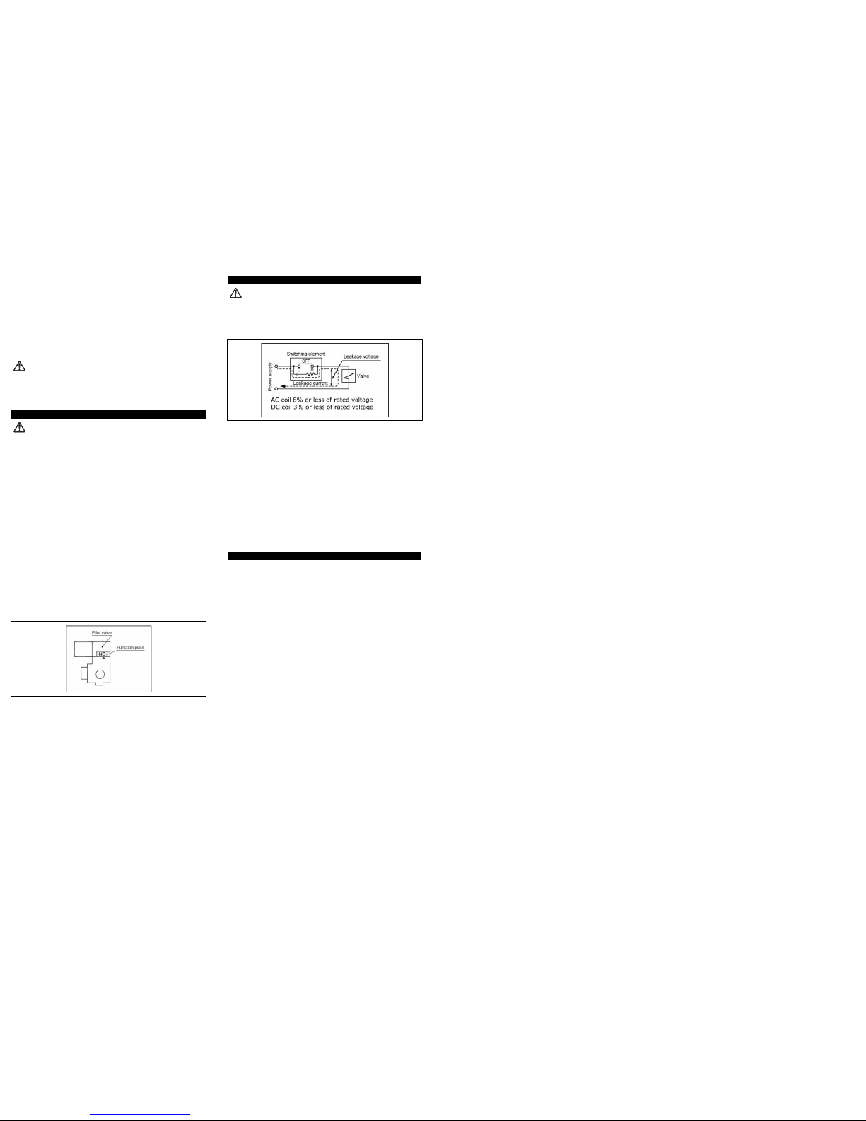
Leakage voltage
Particularly when using a C-R element (surge voltage suppressor) for protection
of the switching element, take note that leakage voltage will increase due to
leakage current flowing through the C-R element, etc.
Drive the solenoid valve for AC with SSR or triac output.
a) Leak current:
If output element's surge circuit has C-R element, slight current flows even
if turned OFF. This causes malfunction on valve reset. When the valve goes
over allowable value shown above, install bleeder resistance.
b) Minimum load capacity (minimum load current)
When valve consumption current is less than minimum load capacity of
output element, or when the margin is small, output element sometimes
cannot change itself. Please consult SMC.
Surge voltage suppressor
If a surge protection circuit contains non-ordinary diodes such as Zener diodes or
ZNRs, a residual voltage that is in proportion to the protective elements and the
rated voltage will remain. Therefore, give consideration to surge voltage
protection of the controller. In the case of diodes, the residual voltage is
approximately 1V.
Low temperature operation
Avoid ambient temperatures outside the range of -10 to 60°C (-5°C minimum for
rubber seals). At low temperatures, appropriate measures should be taken to
avoid solidification or freezing of drainage and moisture, etc.
Mounting direction
All mounting postures are available
6 EUROPEAN CONTACT LIST
6.1 SMC Corporation
Country Telephone Country Telephone
Austria (43) 2262-62 280 Italy (39) 02-92711
Belgium (32) 3-355 1464 Netherlands (31) 20-531 8888
Czech Republic (420) 5-414 24611 Norway (47) 67 12 90 20
Denmark (45) 70 25 29 00 Poland (48) 22-548 50 85
Finland (358) 9-859 580 Portugal (351) 22 610 89 22
France (33) 1-64 76 1000 Spain (34) 945-18 4100
Germany (49) 6103 4020 Sweden (46) 8 603 12 00
Greece (30) 1- 342 6076 Switzerland (41) 52-396 3131
Hungary (36) 23 511 390 Turkey (90) 212 221 1512
Ireland (353) 1-403 9000 United Kingdom (44) 1908-56 3888
6.2 Websites
SMC Corporation www.smcworld.com
SMC Europe www.smceu.com
VP3000*-TFJ0003
 Loading...