

SMC Networks VT325 Series, VO325 Series Operation Manual
Doc. no.VT325∗∗-OMK0002-B
PRODUCT NAME
3 Port Solenoid Valve
MODEL / Series / Product Number
VT(O)325 Series

Contents
Safety Instructions --------------------------------------------------------------------------------- 2,3
Design/Selection ----------------------------------------------------------------------------------- 4,5
Mounting --------------------------------------------------------------------------------------------- 5
Piping ------------------------------------------------------------------------------------------------- 5
Wiring ------------------------------------------------------------------------------------------------- 5
Lubrication ------------------------------------------------------------------------------------------- 6
Air Supply -------------------------------------------------------------------------------------------- 6
Operating Environment --------------------------------------------------------------------------- 6
Maintenance ---------------------------------------------------------------------------------------- 7
Specific Product Precautions -------------------------------------------------------------------- 8~10
Troubleshooting ------------------------------------------------------------------------------------ 11,12
- 1 -
No.VT325∗∗-OMK0002-B
Safety Instructions
These safety instructions ar e int ended to prevent hazardous situations and/or equipme nt damage.
These instructions indicate the level of potential hazar d w it h t he la bels of “Caution,” “Warning” or “Danger.”
They are all important notes for safety and must be followed in addition to International Standards
(ISO/IEC)*1) , and other safety regulations.
*1) ISO 4414: Pneumatic flu id pow er -- General rules relating to systems.
ISO 4413: Hydraulic fluid pow er -- General rules relating to systems.
IEC 60204-1: Safety of machinery -- Electrical equipment of machines .(Part 1: General requirements)
ISO 10218: Manipulating industrial robots -Safety.
etc.
Caution
Caution indicates a hazard with a low level of risk which, if not avoided, could result
in minor or moderate injury.
Warning
Warning
indicates a hazard with a medium level of risk which, if not avoided, could
result in death or serious injury.
Danger
Danger
indicates a hazard with a high level of risk which, if not avoided, will result
in death or serious injury.
Warning
1. The comp ati bil ity of the prod uct i s t he resp on sibi li ty of the perso n who des ig ns th e eq ui pme n t or
decides its specif i cat i ons.
Since the product specified here is used under various operating conditions, its compatibility with specific
equipment must be dec ided by the person who desig ns the equ ipment or dec ides its spec ifications based o n
necessary analysis and test results.
The expected performance and safety assurance of the equipment will be the responsibility of the person who
has determined its compatibility with the product.
This person should also continuousl y review all specifications of the product referring to its latest catalog
information, with a view to giving due consideration to any possibility of equipment failure when configuring the
equipment.
2. Only personnel with appropriat e t r a ining should ope rate machinery and equipment.
The product specified here may become unsafe if handled incorrectly.
The assembly, operation and maintenance of machines or equipment including our products must be
performed by an operator who is appropriately trained and experienced.
3. Do not service or at tempt to remove product and machinery/equipment until safety is confirmed.
1.The inspection and maintenance of machinery/equipment should only be performed after measures to
prevent falling or runaway of the driven objects have been confirmed.
2.When the product is to be removed, confirm that the safety measures as mentioned above are implemented
and the power from any appropriate source is cut, and read and understand the specific product precautions
of all relevant products carefully.
3. Before machinery/equipment is restarted, take measures to prevent unexpected operation and malfunction.
4. Contact SMC beforehand and take special consideration of safety measures if the product is to
be used in any of the following conditions.
1. Conditions and environments outside of the given specifications, or use outdoors or in a place exposed to
direct sunlight.
2. Installation on equipment in conjunction with atomic energy, railways, air navigation, space, shipping,
vehicles, military, medical treatment, combustion and recreation, or equipment in contact with food and
beverages, emergency stop circuits, clutch and brake circuits in press applications, safety equipment or
other applications unsuitable for the standard specifications described in the product catalog.
3. An application which could have negative effects on people, property, or animals requiring special safety
analysis.
4.Use in an interlock circuit, which requires the provision of double interlock for possible failure by using a
mechanical protective function, and periodical checks to confirm proper operation.
- 2 -
No.VT325∗∗-OMK0002-B
Safety Instructions
Caution
1. The product is provided for use in manufacturing industries.
The product herein descr ibed is basically provided for peaceful use in manufacturing indust rie s.
If considering using the product in other industries, consult SMC
beforehand and exchange
specifications or a contract if necessary.
If anything is unclear, contact your nearest sales branch.
Limited warranty and Disclaimer/Compliance Requirements
The product used is subject to the following “Limited warranty and Disclaimer” and “Compliance
Requirements”.
Read and accept them before using the product.
Limited warranty and Disclaime r
1.The warranty period of the product is 1 year in service or 1.5 years after the product is
delivered,whichever is first.
∗
2)
Also, the product may have speci f i ed durability, running distance or replacement parts. Please
consult your nearest sales branch.
2. For any failure or da mage reported within the warranty period which is clearly our responsibility,
a replacement product or necessary parts will be provided.
This limited warr anty applies only to our product independently, and not to any other damage
incurred due to the failure of the product.
3. Prior to using SMC products, please read an d un derstand the warr ant y terms and disclaimers
noted in the specif ied catal og for the par t icular products.
∗
2) Vacu um pads are exclu ded from this 1 year warranty.
A vacuum pad is a consumabl e part, so it i s warranted for a year aft er i t i s del ivered.
Also, even within the warranty period, the wear of a product due to the use of the vacu um
pad or failure due to the deterioration of rubber material are not covered by the limited
warranty.
Compliance Requireme nts
1.
The use of SMC products with production equipment for the manufacture of weapons of mass
destruction(WMD) or any other weapon is strictl y prohibited.
2. The exports of SMC products or technology from one country to another are governed by the
relevant
security laws and regulation of the countries involved in the transaction. Prior to the
shipment of a SMC product to another country, as sure that all loc al rules governing that export
are known and f
ollowed.
Caution
SMC products ar e not i ntended for use as instrum ents for legal metrology.
Measurement instruments that SMC manufactures or sells have not been qualified by type approval tests
relevant to the metrology (measurement) laws of each country.
Therefore, SMC products cannot be used for business or certification ordained
by the metrology
(measurement) laws of each country.
- 3 -
No.VT325∗∗-OMK0002-B
VT325 Series
3 Port Solenoid Valve
Precautions 1
Be sure to read this before handling products.
Design/Selection
1. Confirm the specifications.
This product is designed only for use in compressed air
systems (including vacuum). Do not operate at pressures,
temperatures, etc., beyond the range of s pecifications, as this
can cause damage or malfunction. (Refer to the catalog)
Please contact SMC when using a fluid other than
compressed air (including vacuum).
We do not guarantee against any damage if the product is
used outside of the specification range.
2. Actuator drive
When an actuator, such as a cylinder, is to be driven using a
valve, take appropriate measures (such as the installation of a
cover or the restricting of access to the product) to prevent
potential danger caused by actuator operation.
3. Effects of back pressure when using a
manifold
Use caution when valves are used on a manifold because
actuators may malfunction due to back pressure.
When a single acting cylinder is operated, take appropriate
measures to prevent malfunction by using an individual
exhaust manifold.
4. Holding pressure (including vacuum)
Since valves are subject to air leakage, they cannot be used
for applications such as holding pressure (including vacuum)
in a pressure vessel.
5. Not suitable for use as an emergency shutoff
valve, etc.
The valves presented in this catalog are not designed for
safety applications (e.g. emergenc y shutoff valve). If the valves
are used in such applications, additional safety measures
should be adopted.
6. Release of residual pressure
For maintenance and inspection purposes install a system for
releasing residual pressure.
7. Operation in a vacuum condition
When a valve is used for switching a vacuum, take measures
to install a suction filter or similar to prevent external dust or
other foreign matter from entering inside the valve.
In addition, at the time of vacuum adsorption, be sure to
supply a constant supply of vacuum. Failure to do so may
result in foreign matter sticking to the adsorption pad or air
leakage, causing the workpiece to drop.
8. Regarding va cuu m switch valves and vacuum
release valves
If a non-vacuum valve is i nstalled in the middle of a piping
system that contains a vacuum, the vacuum condition will not
be maintained. Use a valve designed for use under vacuum
conditions.
9. Ventilation
Provide ventilation when using a valve in a confined area,
such as in a closed control panel. For example, install a
ventilation opening, etc., in order to prevent pressure from
increasing inside of the confined area and to release the heat
generated by the valve.
10. Extended periods of continuous energization
Caution for high temperature
∗ The surface temperature of the valve may increase.
● If a valve will be continuously energized for an extended period
of time, the temperature of the valve will increase due to the
heat generated by the coil assembly. Therefore, when it is
continuously energized for an extended period of time or when
the energized period per day is longer than the de-energized
period, use a continuous duty type valve.
Depending on the operating conditions, it may be possible to
use other valves than the ones mentioned above. Please
contact SMC for further information.
Additionally, the use of a valve with N.O. (normally open)
specificationsmakes it p ossible to shorten the energizedtime.
● When the valve is mounted onto a control panel, take
measures against heat radiation in order to keep the valve
temperature within the specified range.
In particular, note that the temperature rise will be larger if three
or more adjacent valves o n t he manifold are energized together
for extended periods of time.
11. Do not disassemble the product or make any
modifications, including additional machining.
Doing so may cause human injury and/or an accident.
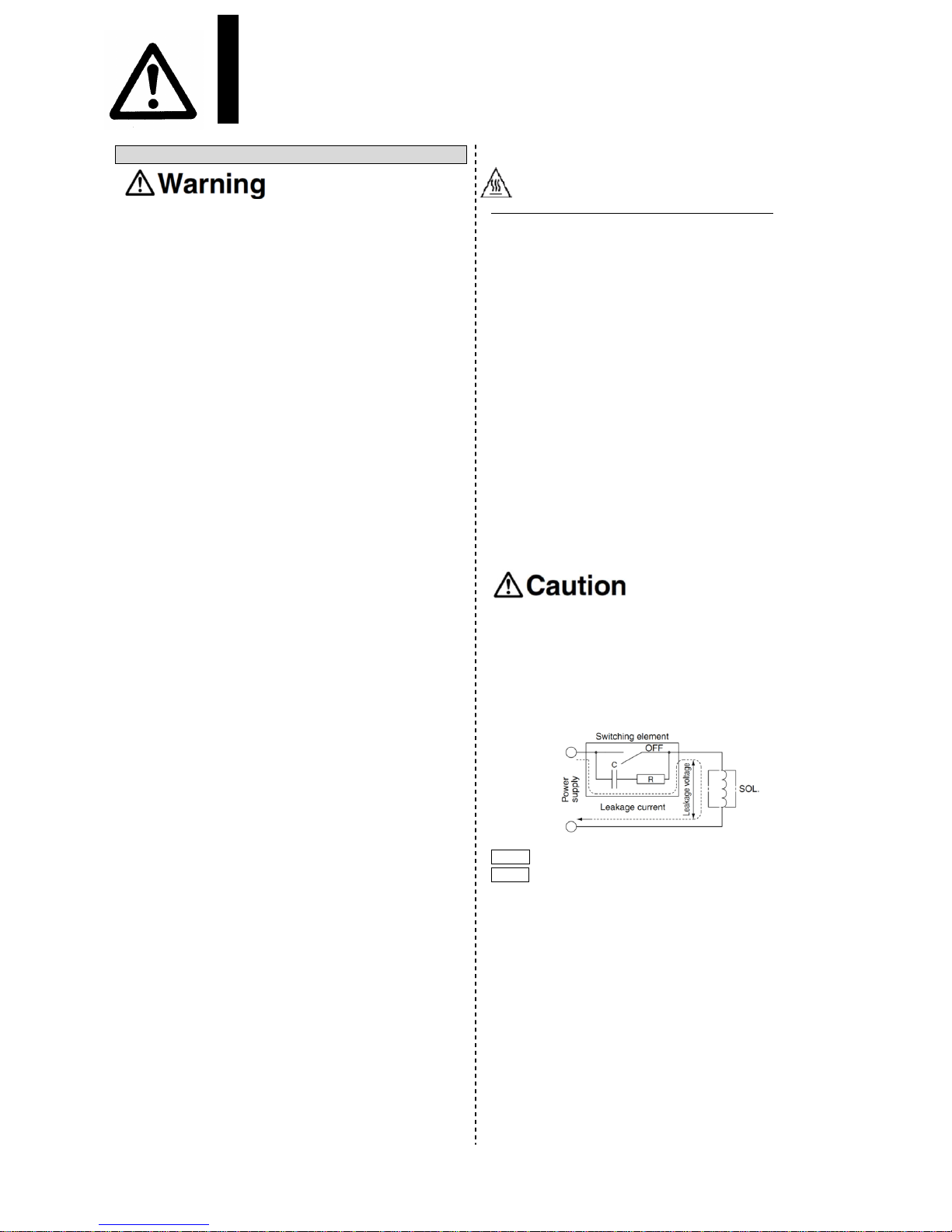
1. Leakage voltage
Take note that the leakage voltage will increase when a
resistor is used in parallel with a switching element or when a
C-R circuit (surge voltage suppressor) is used for protecting a
switching device because of the leakage voltage passing
through the C-R circuit. The suppressor residual leakage
voltage should be as follows.
DC coil 2% or l ess of the rated voltage
AC coil 15% or less of the rated voltage
2. Solenoid valve drive for AC with a solid state
output (SSR, TRIAC output, etc.)
1) Current leakage
When using a snubber circuit (C-R element) for surge
protection of the output, a very small amount of electrical
current will continue to flow even during the OFF state.
This results in the valve not returning. In a situation where
the tolerance is exceeded, as in the above case, take
measures to install a bleeder resistor.
2) Minimum allowable load amount (Min. load current)
When the consumption current of a valve is less than the
output’s minimum allowable load volume or t he margin is
small, the output may not switch normally. Please contact
SMC.
- 4 -
No.VT325∗∗-OMK0002-B
 Loading...