

SMC Networks VKF300 Series Installation And Maintenance Manual
2 INTENDED CONDITIONS OF USE
2.1 Specifications
Note 1) In accordance with dynamic performance test of JIS B 8374-1981 (coil temperature 20ºC,
at rated voltage, without surge voltage suppressor)
Note 2) Impact resistance: No malfunction resulted from test using a drop impact tester. The test
was performed one time each in the axial and right angle directions of the main valve and
armature, for both energized and de-energized status
Vibration resistance: No malfunction resulted in a 45 to 2000Hz one sweep test
performed in the axial and right angle directions of the main valve and armature, for both
energized and de-energized status.
2.2 Circuit Symbols
3 INSTALLATION
WARNING
Do not install unless the safety instructions have been read and understood.
3.1 Environment
WARNING
Do not use in an environment where the product is directly exposed to corrosive gases, chemicals,
salt water, water or steam.
Do not use in an explosive atmosphere.
The product should not be exposed to prolonged sunlight. Use a protective cover.
Do not mount the product in a location where it is subject to strong vibrations and/or shock. Check
the product specifications for above ratings.
Do not mount the product in a location where it is exposed to radiant heat.
Read this manual before using this product.
The information within this document is to be used by pneumatically trained personnel only.
For future reference, please keep manual in a safe place.
This manual should be read in conjunction with the current catalogue.
1 SAFETY RECOMMENDATION
1.1 General recommendation
These safety instructions are intended to prevent a hazardous situation and/or equipment damage. These
instructions indicate the level of potential hazard by label of "Caution", "Warning" or "Danger". To ensure safety,
be sure to observe ISO4414 (Note1), JIS B 8370 (Note2) and other safety practices.
Note1: ISO 4414: Pneumatic fluid power - General rules relating to systems.
Note2: JIS B 8370:Pneumatic system axiom.
WARNING
The compatibility of pneumatic equipment is the responsibility of the person who designs the
pneumatic system or decides its specifications.
Since the products specified here are used in various operating conditions, their compatibility for the
specific pneumatic system must be based on specifications or after analysis and/or tests to meet your
specific requirements.
Only trained personnel should operate pneumatically operated machinery and equipment.
Compressed air can be dangerous if an operator is unfamiliar with it. Assembly, handling or repair of
pneumatic systems should be performed by trained and experienced operators.
Do not service machinery/equipment or attempt to remove components until safety is confirmed.
Inspection and maintenance of machinery/equipment should only be performed after confirmation of safe
locked-out control positions.
When equipment is to be removed, confirm the safety process as mentioned above. Switch off air and
electrical supplies and exhaust all residual compressed air in the system.
Before machinery/equipment is re-started, ensure all safety measures to prevent sudden movement of
cylinders etc. (Bleed air into the system gradually to create backpressure, i.e. incorporate a soft-start
valve).
Contact SMC if the product is to be used in any of the following conditions:
Conditions and environments beyond the given specifications, or if product is used outdoors.
Installations on equipment in conjunction with atomic energy, railway, air navigation, vehicles, medical
equipment, food and beverage, recreation equipment, emergency stop circuits, press applications, or
safety equipment.
An application, which has the possibility of having negative effects on people, property, or animals,
requiring special safety analysis.
CAUTION
Ensure that the air supply system is filtered to 5 micron.
1.2 Conformity to standard
This product if certified to and complies with the following standards:
3.2 Piping
CAUTION
Before piping make sure to clean up chips, cutting oil, dust etc.
When installing piping or fitting into a port, ensure that sealant material does not enter the port inside.
When using seal tape, leave 1.5 to 2 threads exposed on the end of pipe/fitting.
Installation and Maintenance Manual
Series VKF300
3 Port Direct Operated Poppet Solenoid Valve
CAUTION: Operator error could result in injury or equipment damage.
WARNING: Operator error could result in injury or loss of life.
DANGER: In extreme conditions, there is possible result of serious injury or loss of life.
Valve specifications
Type of operation Direct operated 2 position single solenoid
Operating fluid Air
Operating pressure range
Standard 0~0.7MPa
Vacuum -101.2kPa~0.1MPa
Ambient and fluid temperature Maximum 50°C
Response time
Note 1
)
Standard 10ms or less
Low power consumption 15ms or less
Manual operation Non-lock push style
Lubrication Not required
Mounting position Unrestricted
Impact resistance/vibration resistance
Note 2
) 300/50 m/s
2
Enclosure Dust proof
Electrical specifications
Electrical entry Grommet (G), DIN terminal (D)
Rated voltage
AC 100V, 110V, 200V, 220V, 240V
DC 6V, 12V, 24V, 48V
Allowable voltage fluctuation ±10% of rated voltage
Standard Starting 9.5VA/50Hz, 8VA/60Hz
Holding 7VA/50Hz, 5VA/60Hz
Power consumption (DC)
Without light 4W (standard), 2W
(low power consumption type)
With light 4.3W (standard), 2.3W
(low power consumption type)
Surge voltage suppressor
AC Varistor
DC Diode (varistor for 12VDC or less)
Indicator light
AC Neon bulb
DC LED
Apparent
power (AC)
EMC Directive EN 61000-6-2, EN 55011
Low Voltage Directive DIN VDE 0580
Thread Appropriate tightening torque (Nm)
M5 1.5 to 2
Rc 1/8 7 to 9
X
Symbol
(A)
2
1
(P)3(R)
Rc 1/8
(port A)
Rc 1/8,
M5x0.8
(port A)
2-M5x0.8
(ports P, R)
Rc 1/8
(port P, R)
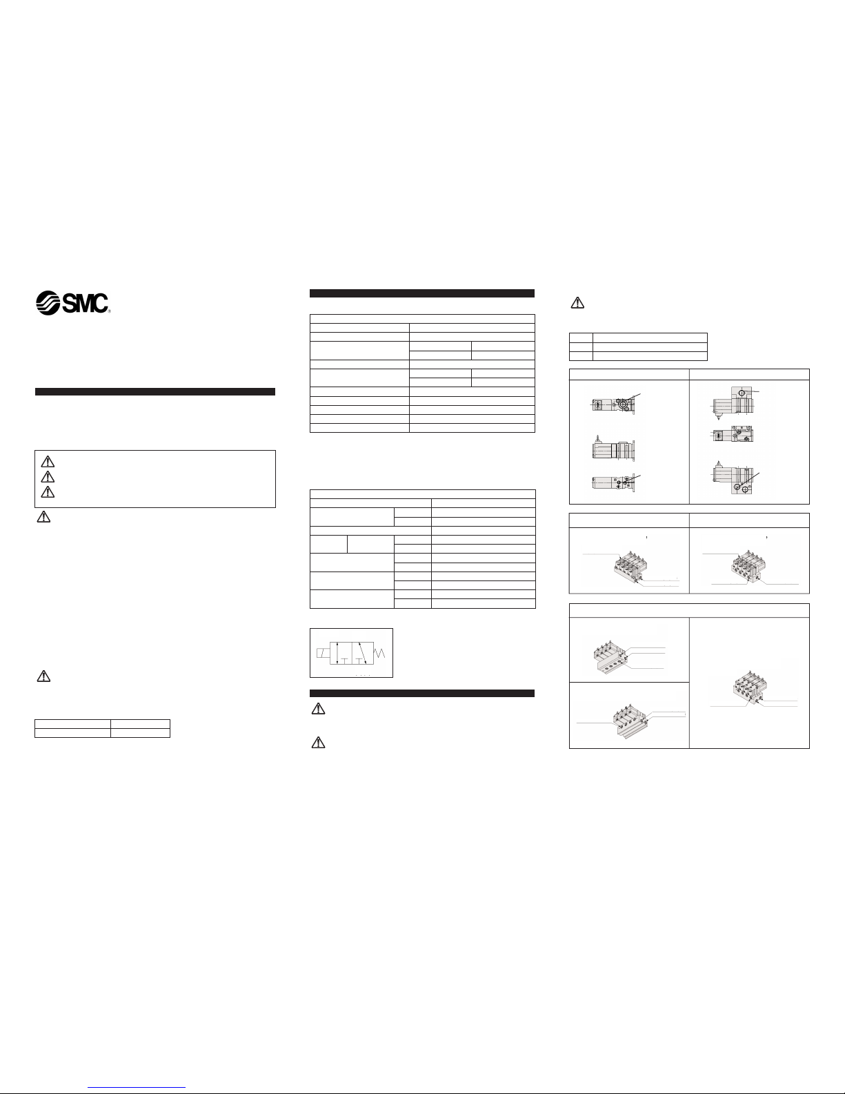
Single type, body ported type
Single type, base mounted type
Manifold, body ported type.
Common SUP, Common EXH
Manifold, body ported type.
Common SUP, Individual EXH
Port A:
Rc 1/8, M5x0.8
Port R: Rc 1/8
Port P: Rc 1/8
Type 21/for body ported type
(Port A top ported)
Port A:
Rc 1/8, M5x0.8
Port P: Rc 1/8
Type 20/for body ported type
(Port A top ported)
Port R: Rc 1/8
Manifold, base mounted type.
Common SUP, Common EXH
Port R: Rc 1/8
Type 42/for base mounted type
(Port A side ported)
Port P: Rc 1/8
Type 40/for base mounted type
(Port A bottom ported)
Port R: Rc 1/8
Port P: Rc 1/8
Port A: Rc 1/8
Port A: Rc 1/8
Type S42
(solenoid on same side as port A)
Port P: Rc 1/8
Port R: Rc 1/8
Port A: Rc 1/8
VKF300-TFH35GB
3.3 Electrical connection
CAUTION
When DC power is connected to a solenoid valve equipped with light and/or surge voltage suppressor, check
for polarity indications.
For polarity indications:
No diode to protect polarity: if polarity connection is wrong, the diode in the valve or switching device at
control equipment or power supply may be damaged.
With diode to protect polarity: if polarity connection is wrong, the valve does not switch.
CAUTION: Light/surge CAUTION: Connection of 24V
voltage suppressor or more DC
For the grommet type, connect the positive (+) side to the red
lead wire and connect the negative (-) side to the black lead wire.
For the DIN terminal, connect the positive (+) side to the
connector’s No.1 terminal and connect the negative (-) side to the
No.2 terminal.
(See the markings on the terminal block.)
For 12V or less DC, positive (+) and negative (-) can be
connected in either direction.
CAUTION: Use of DIN Connector
Connection procedure
Loosen the holding screw, and pull the connector out of the solenoid valve terminal block.
After removing the holding screw, insert the flat head screw driver, etc. into the notch on the bottom of
the terminal block and pry it up, separating the
terminal block and the housing.
Loosen the terminal screws (slotted screws) on
the terminal block, insert the core of the lead
wire into the terminal in accordance with the
prescribed connection method, and attach
securely with the terminal screws.
Fasten the cord by screwing in the gland nut.
Cord entry changing procedure
After separating the terminal block and housing,
the cord entry direction can be changed by
attaching the housing in the desired direction
(4 directions in 90° increments).
*When equipped with light, handle with care so
that the light is not damaged by the cord’s lead
wires, etc.
Precautions
The connector should be inserted and pulled out in a straight line without tilting diagonally.
Compatible cables
Cord outside diameter: ø4 to ø6.5 (Reference)
0.5mm
2
equivalent to JISC3306, 2 wire or 3 wire
Connector part no.: VK300-37-1
Part No. for connector with light Circuit diagram for connector with light
Rated voltage Rating symbol Part No.
100VAC A1 VK300-37-2-01
200VAC A2 VK300-37-2-02
240VAC A3 VK300-37-2-07
6VDC LW06 VK300-37-4-51
12VDC LW2 VK300-37-4-06
24VDC LD4 VK300-37-3-05
48VDC LD8 VK300-37-3-53
3.4 Mounting
CAUTION
After confirming the installation of the
gaskets, securely tighten the screws to the
tightening torque shown in the table below:
The bushing may be damaged if the tightening
torque of 0.8Nm is exceeded. In the event that
damage does occur, be sure to replace the
bushing.
2 sets per unit are required.
3.5 Lubrication
CAUTION
SMC products have been lubricated for life at manufacturer, and do not require lubrication in
service.
If a lubricant is used in the system, use turbine oil Class 1(no additive), ISO VG32. Once lubricant
is used in the system, lubrication must be continued because the original lubricant applied during
manufacturing will be washed away.
4 SETTINGS AND PROGRAMMING
4.1 Manual override operation
WARNING
When the manual override is operated, connected equipment will be actuated.
Confirm safety before operating.
Non-locking push type (tool required)
There are manual overrides in 2 directions, on
the top and on the side (solenoid side).
By pressing either of the manual overrides in
the direction of the arrow (→) until it stops
(approx. 1mm), it will turn ON, and it turns
OFF when released.
5 MAINTENANCE
WARNING
Not following proper procedures could cause the product to malfunction and could lead to damage
to the equipment or machine.
If handled improperly, compressed air can be dangerous. Assembly, handling and repair of
pneumatic system should be performed by qualified personnel only.
Drain: remove condensate from the filter bowl on a regular basis.
Shut-down before maintenance: before attempting any kind of maintenance make sure the supply
pressure is shut off and all residual air pressure is released from the system to be worked on.
Start-up after maintenance: apply operating pressure and power to the equipment and check for
proper operation and possible air leaks. If operation is abnormal, please verify product set-up
parameters.
Do not make any modification to the product
Do not disassemble the product, unless required by installation or maintenance instructions.
5.1 Manifold mounting
Refer to paragraph 3.4, for mounting valves onto manifolds.
6 LIMITATIONS OF USE
WARNING
Do not exceed any of the specifications laid out in section 2 of this document or the specific product
catalogue.
Long continuous loading time
When power will be applied continuously for extended periods of time, use type VKF33*E. However, it cannot
be used with high frequency. Contact SMC if it will be operated more than once a day.
Be sure to perform switching at least once every 30 days.
CAUTION
Leakage voltage
Particulary when using a resistor in parallel with a switching
element, take note that leakage voltage will increase due to
leakage current flowing through the resistor. Limit the
amount of residual leakage voltage to the following values.
For AC coil: 20% or less of rated voltage
For DC coil: 2% or less of rated voltage
Low temperature operation
Operation is possible to -10°C, but measures should be taken to avoid solidification or freezing of drainage
and moisture, etc.
Mounting orientation
The mounting orientation is unrestricted.
7 EUROPEAN CONTACT LIST
SMC Corporation
Country Telephone Country Telephone
Austria (43) 2262-62 280 Italy (39) 02-92711
Belgium (32) 3-355 1464 Netherlands (31) 20-531 8888
Czech Republic (420) 5-414 24611 Norway (47) 67 12 90 20
Denmark (45) 70 25 29 00 Poland (48) 22-548 50 85
Finland (358) 9-859 580 Portugal (351) 22 610 89 22
France (33) 1-64 76 1000 Spain (34) 945-18 4100
Germany (49) 6103 4020 Sweden (46) 8-603 0700
Greece (30) 1- 342 6076 Switzerland (41) 52-396 3131
Hungary (36) 1-371 1343 Turkey (90) 212 221 1512
Ireland (351) 1-403 9000 United Kingdom (44) 1908-56 3888
Websites
SMC Corporation www.smcworld.com
SMC Europe www.smceu.com
Bushing assembly part no. VKF300-6A-1
Grommet type
DIN terminal
Red (+)
Black (-)
Surge voltage
suppressor
* Marking
Light
(built into connector
Surge voltage
suppressor
(built into
terminal block)
* Markings
For 24V or more DC
For AC and 12V or less DC
1
(-)
(+)
2
Gland nut
Washer
Grommet
(rubber)
Holding screw
Light mounting location
Terminal block
Notch
Terminal screw
(3 places)
Rating symbol
(see table below)
Housing
Appropriate tightening torque (Nm)
0.6 to 0.8
AC
Circuit diagram
12VDC or less
Circuit diagram
24VDC or more
Circuit diagram
LED
NL
R
LED
R
R
2
2
2
1
1
1
NL: Neon light
R: Resistor
LED: Light emitting diode
R: Resistor
D: Protective diode
LED: Light emitting diode
R: Resistor
Mounting screw
Bushing
Switching element
Valve
OFF
Leakage current
Power
supply
Resistor
Leakage
voltage
Hole dia. ø5
ø9
D
VKF300-TFH35GB
 Loading...