

SMC Networks VK300 series, VK3000 series Installation And Maintenance Manual
Installation and Maintenance Manual
Series VK300 and VK3000 3 Port and 5 Port
Direct Operating Solenoid Valves
This Manual should be read in conjunction with the current product Catalogue
For future reference,please keep this manual in a safe place
Safety Instructions
These safety instructions are intended to prevent a hazardous
situation and/or equipment damage.These instructions indicate the
level of potential hazard by label of “Caution”,“Warning” or
“Danger”.To ensure safety, be sure to observe ISO4414
(Note1)
, JIS B
8370
(Note2)
and other safety practices.
Note 1: ISO 4414: Pneumatic fluid power – Recommendations for the
application of equipment to transmission and control systems.
Note 2: JIS B 8370: Pneumatic system axiom.
CAUTION : Operator error could result in injury or
equipment damage.
WARNING: Operator error could result in serious
injury or loss of life.
DANGER : In extreme conditions, there is a
possible result of serious injury or loss of life.
WARNING
1. The compatibility of pneumatic equipment is the
responsibility of the person who designs the pneumatic
system or decides its specifications.
Since the products specified here are used in various operating
conditions, their compatibility for the specific pneumatic system
must be based on specifications or after analysis and/or tests to
meet your specific requirements.
2. Only trained personnel should operate pneumatically
operated machinery and equipment.
Compressed air can be dangerous if an operator is unfamiliar
with it.Assembly, handling or repair of pneumatic systems should
be performed by trained and experienced operators.
3. Do not service machinery/equipment or attempt to
remove component until safety is confirmed.
1) Inspection and maintenance of machinery/equipment should
only be performed after confirmation of safe locked-out
control positions.
2) When equipment is to be removed, confirm the safety process
as mentioned above.Switch off air and electrical supplies and
exhaust all residual compressed air in the system.
3) Before machinery/equipment is re-started, ensure all safety
measures to prevent sudden movement of cylinders etc.
(Bleed air into the system gradually to create back-pressure,
i.e. incorporate a soft-start valve).
4. Contact SMC if the product is to be used in any of the
following conditions:
1) Conditions and environments beyond the given
specifications, or if product is used outdoors.
2) Installations in conjunction with atomic energy, railway, air
navigation, vehicles, medical equipment, food and beverage,
recreation equipment, emergency stop circuits, press
applications, or safety equipment.
3) An application which has the possibility of having negative
effects on people, property, or animals, requiring special
safety analysis.
CAUTION
Ensure that the air supply system is filtered to 5 micron.
ISO Symbol (Fig 1) Installation
WARNING
Before commencing installation ENSURE Air and Power supplies are
ISOLATED
DO NOT install these Valves in explosive atmospheres
DO NOT install these Valves in Corrosive Environments
If it is intended to energise a Valve for an extended period Consult
SMC
Protect Valves from Water / Oil splashes and Welding spatter.
Ensure Valves are protected from freezing
When changing Voltages the Valve must be replaced completely.
These Valves cannot be dismantled due to their Structure.
Using VK300 Series for Vacuum
If it is proposed to use the VK300 in Vacuum applications ensure that
the VK33*V,and VK33*W types are specified.
CAUTION
The preveous mentioned Valves differ from that of Vacuum retention
types.
When using Vacuum pads mount an Air suction filter (ZF Series)
between the Vacuum pad and the Valve to prevent dust from entering
the Valve.
Use a silencer in the Exhaust port.
CAUTION
Prolonged Energisation
Specify VK33*E Type for the above application and ensure that the
Valve is switched every 30 days. For Emergency Dump operation
please consult SMC.
VK3000 Series
The Air supply Port is the No.1 port of this Series,and cannot be used
in Vacuum applications.
Using VK3000 as a 3 Port Valve
It is possible to convert the VK 3000 into a 3 Port V alve either Normally
Open or Normally closed by plugging a Cylinder Port, see below:
Plug position Port No.2 Port No.4
Operation N.C N.O
JIS Symbol
WARNING
ENSURE THAT THE EXHAUST PORTS ARE LEFT OPEN WHEN
CONVERTING A VALVE T O 3 PORT CONFIGURATION.
VK3000 Series (Fig 3)
082A/ENGLISH
VK300 VK3000
Specifications
Type of operation Direct operated 2-position single solenoid
Operating fluid Air
Standard 0~0.7MPa {0~7.1kgf/cm2}
Operating pressure range
Vacuum -101.2kPa~0.1MPa {1Torr~1kgf/cm
2
}
Ambient temperature and operating
fluid temperature
MAX. 50 ºC
Standard 10ms or less
* Response time
Low watt 15ms or less
Manual Operation Non-lock push type
Lubrication Unnecessary
Mounting position Any position
** Impact, vibration resistance 300m/s2, 50m/s
2
Protection IP65
* In accordance with the dynamic performance test of JIS B 8374-1981 (at the rated voltage, without surge suppressor).
** Impact resistance: No malfunction from test using drop impact tester to axis and right angle direction of main valve and armature,each
one time when energised and de-energised.
Vivration resistance: No malfunction from test with from 8.3 to 2000Hz 1 sweep to axis and right angle direction of main valve and
armature each time when energised and de-energised (Value in the initial stage).
Solenoid Specifications
Electrical entry DIN type terminal (D)
AC 100V,110V,200V,220V,240V
Rated voltage
DC 6V,12V,24V,48V
Allowable voltage ±10%
Inrush 9.5VA/50Hz,8VA/60Hz
Apparent power
Holding 7VA/50Hz, 5VA/60Hz
Standard 4W
Power consumption
Low watt 2W
AC Varistor
Surge voltage protection circuit
DC Diode (12V or less :Varistor)
AC Neon glow lamp
Indicator light
DC LED
Fig 1
Plug
Plug
Fig 3
2
3
1
4
2
5
1
3
4
2
4
2
513
513
(1) Model VK3120
(2) Model VK3140
M3X26
Screw W/Spring
washer
Manifold gasket
DXT199-23-4
M3X8
Screw W/Spring
washer
Blanking plate
VK300-33-3
VK3000-7-1
Manifold gasket for blanking plate
VK3000-6-3
M3X26
Screw W/Spring
washer
DXT199-23-4
VK3120-OG-01
VK3140-OG
VK3000-6-1
Manifold gasket
VK3000-6-2
Applicable base
Model VV5k3-20
Model VV5k3-21
Manifold base
}
Applicable base
VK3000-9-1
Model VV5k3-40
Model VV5k3-(S)41
Model VV5k3-(S)42
Manifold base
Subplate
}
(3) Blanking plate Ass’y
Parts No.: VK3000-7-1A
Applicable base: common for all VV5k3 models
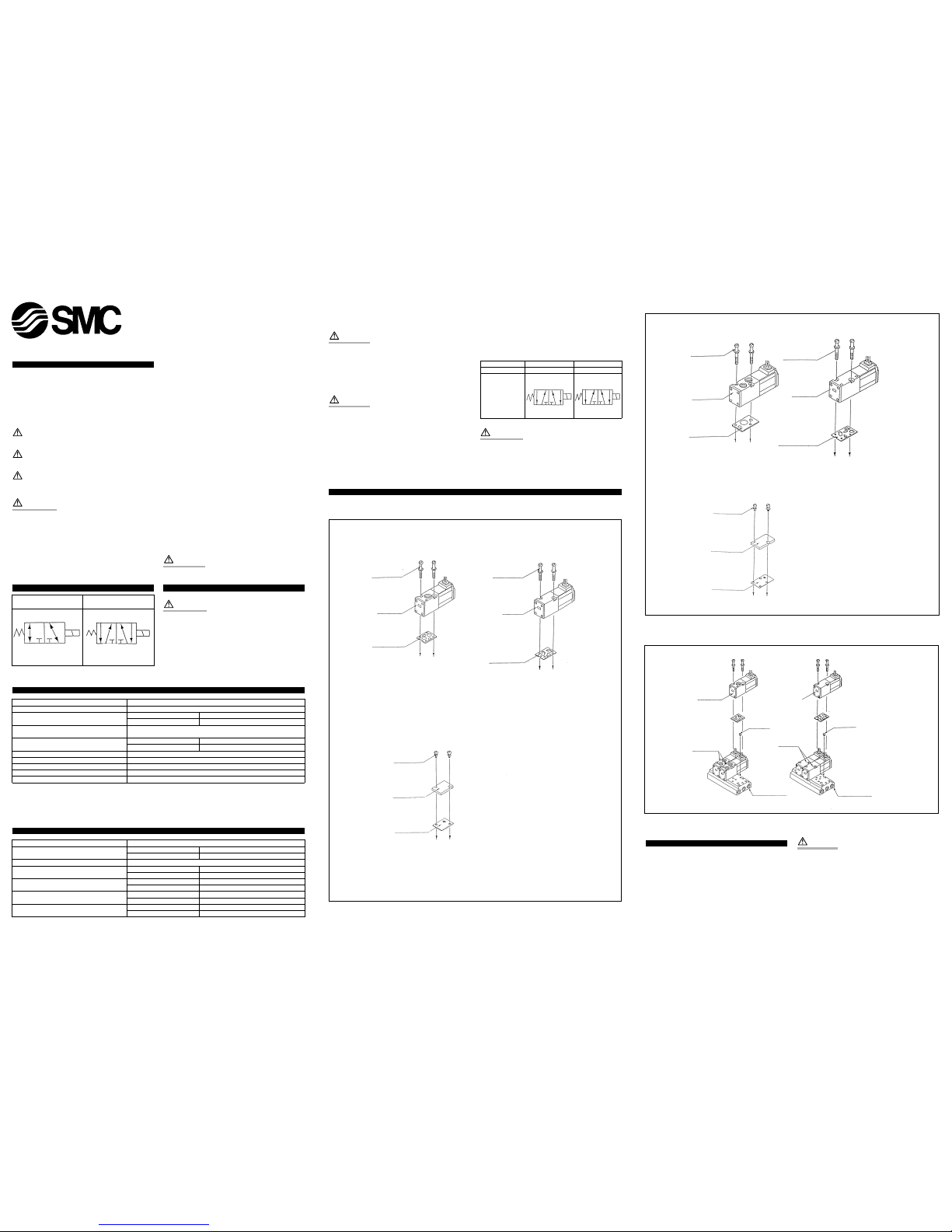
Manifold (Installation of Solenoid Valve and Blanking Plate)
VK300 Series (Fig 2)
Fig 2
(1) Model VK332
(2) Model VK334
M3X26
Screw W/Spring
washer
Manifold gasket
DXT199-23-4
M3X26
Screw W/Spring
washer
DXT199-23-4
VK332-OG-01
VK334-OG
VK300-41-1
VK300-33-3
Manifold gasket
VK300-41-2
Applicable base
Model VV3k3-20
Model VV3k3-21
Model VV5k3-20
Model VV5k3-21
Manifold base
Manifold base
Subplate
}
Applicable base
VK300-45-1
Model VV3k3-40
Model VV3k3-(S)42
Model VV5k3-40
Model VV5k3-(S)41
Model VV5k3-(S)42
(3) Blanking plate Ass’y
Parts No.: VK300-42-1A
M3X8
Screw W/Spring
washer
VK300-42-1
Blanking plate
VK300-41-3
Manifold gasket for
blanking plate
Applicable base: common for all VV3k3 models
}
Mixed Mounting of VK300 Series and VK3000 Series (Fig 4)
It is possible to mount the VK300 onto the Manifold base of the
VK3000 Series.
(1) When specifying VV5K3-20 or VV5K3-40, ensure that the
appropriate Exhaust Port on the Manifold base is PLUGGED
using a rubber plug part No. VK3000-8-1, as this Exhaust port
becomes redundant when mounting 3 port Valves.
(2) The 3 port Valve can also be mounted on additional Manifolds i.e.
VV5K3-21, VV5K3-(S)41 and VV5K3-(S) 42 without additional
modifications.
CAUTION
• When converting a 5 port Valve, from 3 ports back to 5 ports
ensure that the exhaust plug is removed.
• When a 3 port Valve (VK300) is Mounted onto the Manifold base
of the VK3000 Series, the Valve function will be NORMALLY
CLOSED. If a NORMALLY OPEN function is required plug port No. 4
of a 5 port Valve.
• When piping from the Manifold base,the port No. 2, of the 3 port
Valve becomes the port No. 4 of the 5 port Valve. To avoid the
possibility of incorrect piping to the port No. 2 ensure that the
port No. 2 is plugged.
Fig 4
Model VV5K3-20
VK332-OG-01
VK3120-OG-01
Plug
VK3000-8-1
Plug
VK3000-8-1
Notch mark
(Recession)
Notch mark
(Recession)
VK334-OG
Model VV5K3-40
VK3140-OG
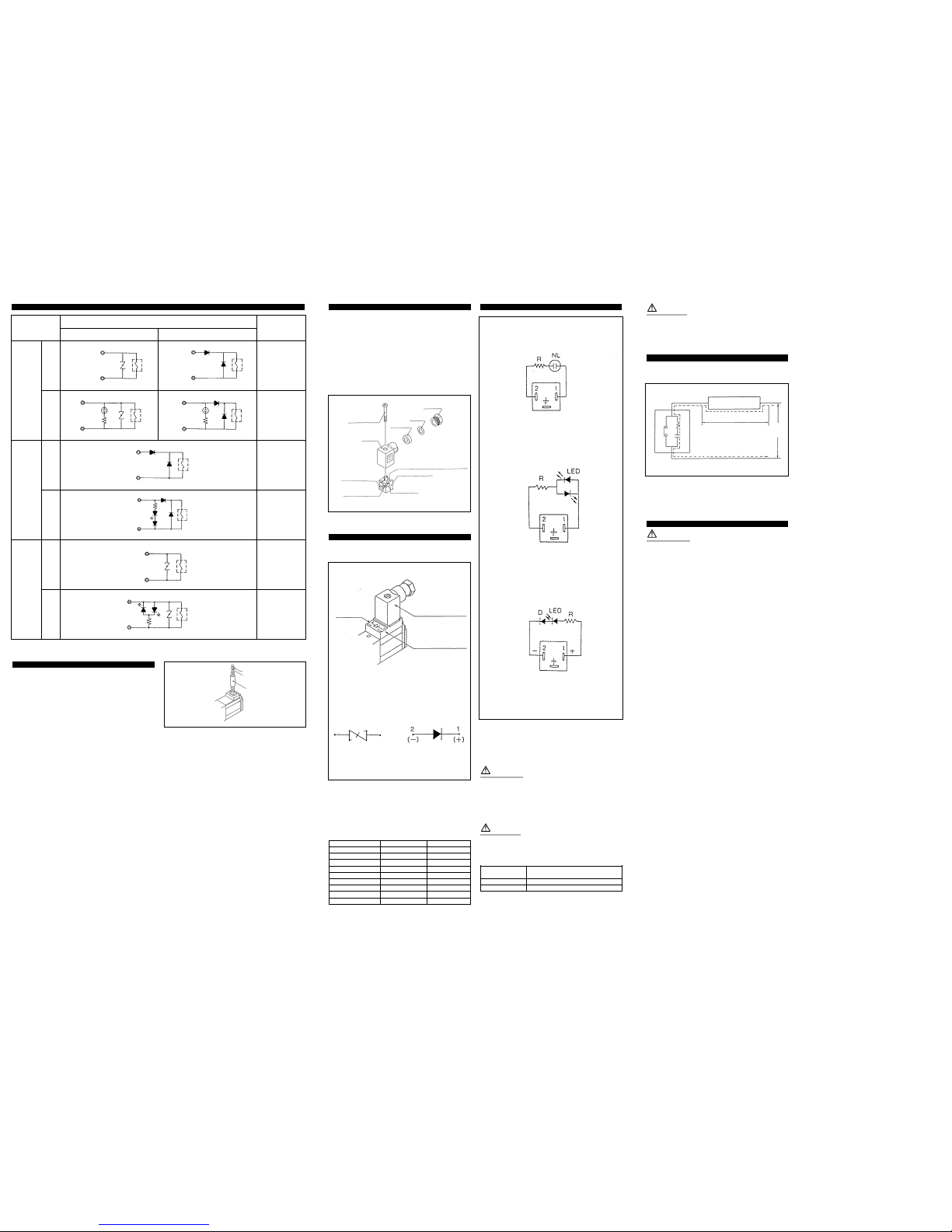
DIN Type Connector (Fig 6)
Connecting
Undo the fixing screw and remove the connector from the Solenoid
Valve terminal block.
After removing the fixing screw, insert a slotted screwdriver into the
slotted area at the bottom of the terminal block and the housing,and
lever open to separate the terminal block and the housing.
Undo the terminal screws of the block, insert the conductor of the
cable into the terminal and tighten the conductor via the terminal
screw.
Select the terminal housing direction, best suited for the application,
and insert the terminal block into the housing until it clicks into place.
Hand tighten the gland nut to retain the wires.
Connection Method for Lamp/Surge Voltage Protection Circuit (Fig 7)
When using a DIN connector with DC voltage connect the positive side
(-) to the symbol 2 of the terminal block.
Part No.of the connector without lamp:
VK300-82-1
Part No.of the connector with lamp:
Refer to the following table
Rated voltage *Marking Parts No.
AC100V 100V VK300-82-2-01
AC110V 110V VK300-82-2-03
AC200V 200V VK300-82-2-02
AC220V 220V VK300-82-2-04
AC240V 240V VK300-82-2-07
DC6V 6V VK300-82-4-51
DC12V 12V VK300-82-4-06
DC24V 24VD VK300-82-3-05
DC48V 48VD VK300-82-3-53
*Indicated on the terminal block.
Circuit Drawings (Fig 8)
Changing the Direction of the Connector (Cable)
After separating the Terminal block from the housing, the cable
direction can be changed 4 ways at 90º intervals.
WARNING
If the connector is fitted with a lamp, ensure that the lamp is not
damaged by the lead wire of the cable.
Applicable Cable. ( 2 conductors or 3* conductors)
Outside diameter of the cable should be ø3.5 ~ ø7mm.
Note 3 Conductor cables are used when connecting to Ground.
CAUTION
Ensure that the connector is straight during insertion or removal.
Piping tightening torque
Connecting screw
Appropriate tightening torque
N•m {kgf•cm}
M5 1.5~2{15~20}
Rc (PT) 1/8 7~9 {70~90}
Lubrication
The valve has been lubricated for life on assembly and requires no
additional lubrication.
CAUTION
However,if a lubricant is to be used, a turbine oil type #1 (ISO VG32)
should be used.
If a lubricant is used,continuous lubrication must be carried out as the
original lubricant will be washed away.
Voltage Leakage (Fig 9)
If using a C-R element in parallel with the switching element, the
leakage voltage will increase as the current flows through the C-R
element.
Keep the residual leakage voltage to 20% or less of the rated voltage
for AC coils and 2% or less of the rated voltage for DC coils.
Maintenance
WARNING
When changing the rated voltage the valve MUST be replaced,as it is
NOT possible to change the coil.
It is NOT possible to dismantle the valve due to its design.
Application of undue force to the valve may damage the valve section.
Lamp and Surge Protection Circuits
Rated
voltage
AC
DC
24V
48V
DC
6V
12V
Without lampWith lampWithout lampWith lampWithout lampWith lamp
DIN terminal (D)
Model No.
symbol
S
S
S
Z
Z
Z
Neon glow
lamp
Grommet Type Connector (Fig 5)
When using a surge Voltage protection circuit, with DC, connect the
positive side to the Red lead wire and the Negative side to the Black
lead wire.
When using AC voltage,the Blue lead wire is for 100VAC,and the Red
lead wire is for 200VAC,.The Grey lead wire is for other Voltages.
Fig 5
Fig 8
Fig 7
Varistor
Varistor
LED
LED
Varistor
No.1
No.2
No.2
No.1
(+)
No.2
(-)
Diode
No.1
(+)
No.2
(-)
Diode
Red (+)
Black (-)
}
DC type
Surge voltage
protection circuit
Fig 9
When you enquire about the product, please contact the following
SMC Corporation:
ENGLAND Phone 01908-563888 TURKEY Phone 212-2211512
ITALY Phone 02-92711 GERMANY Phone 6103-402-0
HOLLAND Phone 020-5318888 FRANCE Phone 01-64-76-10-00
SWITZERLAND
Phone 052-396 31 31 SWEDEN Phone 08-603 07 00
SPAIN Phone 945-184100 AUSTRIA Phone 02262-62-280
Phone 902-255255 IRELAND Phone 01-4501822
GREECE Phone 01-3426076 DENMARK Phone 70 25 29 00
FINLAND Phone 09-68 10 21 NORWAY Phone 67-12 90 20
BELGIUM Phone 03-3551464 POLAND Phone 48-22-6131847
PORTUGAL Phone 02-610 8922
*Marking
*Marking
For AC and DC 12V or less
For DC 24V or more
Light (built in connector)
Surge voltage protection circuit
(built into the terminal block)
AC circuit drawing
NL: Neon lamp
R: Resistor
DC circuit drawing
12V or less
LED: Light emitting diode
R: Resistor
DC circuit drawing
24V or more
D: Protective diode
LED: Light emitting diode
R: Resistor
*Contact point
C-R element
Current leakage
Voltage leakage
Valve
Power
source
Coil
Coil
Coil
Coil
Coil
Coil
Coil
Coil
No.1
No.2
No.1
No.2
No.1
Neon glow
lamp
Standard, Y, V & W type
Long-time energizing model (E)
Diode
Diode
No.2
No.1
No.2
No.1
Varistor
Fig 6
Fixing screw
Housing
(Code)
Refer to table
below
Terminal screw
(3 places)
Slotted area
(Light installation position)
Terminal block
Grommet
(Rubber)
Washer
Gland nut
 Loading...