

SMC Networks VJ3000,VJ5000,VJ7000 Installation And Maintenance Manual
Installation and Maintenance Manual
VJ3000, 5000, 7000, 4,5 Port Solenoid Valves
This Manual should be read in conjunction with the current Catalogue.
For future reference, please keep this manual in a safe place
Safety Instructions
These safety instructions are intended to prevent a hazardous situation and/or equipment damage.These instructions indicate the level
of potential hazard by label of “Caution”,“Warning” or “Danger”.
To ensure safety,be sure to observe ISO4414
(Note1)
, JIS B 8370
(Note2)
and other safety practices.
Note 1: ISO 4414:Pneumatic fluid power – Recommendations for the
application of equipment to transmission and control systems.
Note 2: JIS B 8370: Pneumatic system axiom.
CAUTION : Operator error could result in injury or
equipment damage.
WARNING: Operator error could result in serious
injury or loss of life.
DANGER : In extreme conditions, there is a
possible result of serious injury or loss of life.
WARNING
1. The compatibility of pneumatic equipment is the responsibility of the person who designs the pneumatic system
or decides its specifications.
Since the products specified here are used in various operating
conditions, their compatibility for the specific pneumatic system
must be based on specifications or after analysis and/or tests to
meet your specific requirements.
2. Only trained personnel should operate pneumatically
operated machinery and equipment.
Compressed air can be dangerous if an operator is unfamiliar
with it.Assembly, handling or repair of pneumatic systems should
be performed by trained and experienced operators.
3. Do not service machinery/equipment or attempt to
remove component until safety is confirmed.
1) Inspection and maintenance of machinery/equipment should
only be performed after confirmation of safe locked-out
control positions.
2) When equipment is to be removed, confirm the safety process
as mentioned above.Switch off air and electrical supplies and
exhaust all residual compressed air in the system.
3) Before machinery/equipment is re-started, ensure all safety
measures to prevent sudden movement of cylinders etc.
(Bleed air into the system gradually to create back-pressure,
i.e. incorporate a soft-start valve).
4. Contact SMC if the product is to be used in any of the
following conditions:
1) Conditions and environments beyond the given specifica-
tions, or if product is used outdoors.
2) Installations in conjunction with atomic energy, railway, air
navigation, vehicles,medical equipment, food and beverage,
recreation equipment, emergency stop circuits, press
applications, or safety equipment.
3) An application which has the possibility of having negative
effects on people, property, or animals, requiring special
safety analysis.
CAUTION
Ensure that the air supply system is filtered to 5 micron.
Specifications
VJ3000 VJ5000 VJ7000
Fluid Air Air Air
Operating pressure
2 position single solenoid
0.15~0.7 (1.5~7.1) 0.15~0.7 (1.5~7.1) 0.15~0.7 (1.5~7.1)
range MPa kgf/cm
2
2 position double solenoid
0.1~0.7 (1~7.1) 0.1~0.7 (1~7.1) 0.1~0.7 (1~7.1)
3 position valve 0.2~0.7 (2~7.1) 0.15~0.7 (1~7.1) 0.15~0.7 (1~7.1)
Ambient and fluid temperature (ºC) Max. 50 Max. 50 Max.50
Response time (ms)
2 position, single,double
15 or less 25 or less 30 or less
(at 5 kgf/cm2)
Note 1)
3 position 30 or less 40 or less 60 or less
Max. operating
2 position, single,double
10 5 5
frequency (Hz) 3 position 3 3 3
Manual override
Non-locking push type, Non-locking push type, Non-locking push type,
slotted locking type slotted locking type slotted locking type
Pilot exhaust
Individual pilot exhaust, Individual pilot exhaust, Individual pilot exhaust,
common exhaust for main common exhaust for main common exhaust for main
and pilot valve and pilot valve and pilot valve
Lubrication Not required Not required Not required
Mounting position Free Free Free
Impact/vibration resistance (G)
Note 2)
150/30 150/30 150/30
Protection structure IP40 IP40 IP40
Note 1: As per JIS B8375-1981 (Coil temperature; 20°C, without surge voltage suppresser at rated voltage).
Note 2: Shock resistance - - - -No malfunction from test using drop impact tester, to axis and right angle and armature,each one time when
energized and de-energized.
Vibration resistance - - No malfunction from test with 8.3 to 2000Hz 1 sweep,to axis and right angle direction of main valve and
armature, each one time when energized and de-energized.(Primary value).
Electrical connection L/M type plug connector (Fig 2)
1. Insertion: Push the connector straight onto the pins of the solenoid making sure the lip of the lever securely “locks” into the
groove of the solenoid cover.
2. Removal: Press the lever against the connector housing and pull
it away from solenoid.
Connection/Disconnection of socket to connector (Fig 3)
Connection
Insert a socket complete with lead attached into square hole (marked
+, -) of connector.Push firmly until hook engages. Confirm engagement by lightly pulling the lead.
Disconnection
To disconnect socket and lead assembly from the connector insert a
pin of approximately 1mm diameter into the hole in the connector,
located on the opposite side to the lever. Depress the hook on the
socket and withdraw.If the socket is to be re-used, gently spread the
hook of the socket.
Surge voltage protection circuit (Fig 4)
DC
Ensure that connections are made to the (plus) and (minus)
terminals on the connector.
Pre-wired solenoids will have red leads connected to the +(plus) terminal and black leads connected to the -(minus) terminal.
WARNING
Incorrect connection may result in failure of diode or switching element.
Leakage voltage (Fig 5)
Note that when using a C-R device (surge voltage suppresser) for contact protection, the voltage leakage may increase due to the current
leakage flowing through the C-R device.
Suppress residual voltage leakage as follows:
DC Coil 3% or less of rated voltage
Wire each valve on the manifold to integral printed circuit board.
External connection is made by flat cable via a 26 pole MIL type
connector.
Lubrication
These valves have been lubricated for life during manufacture and as
such require no further lubrication.
CAUTION
However,if a lubricant is to be used with a rubber seal type, a turbine
oil type #1, (ISO VG32) should be used.Continuous lubrication must
be carried out as the original lubricant will be washed away.
Manual override operation (Fig 8)
WARNING
Exercise EXTREME CAUTION when operating a solenoid manual override as connected equipment will commence operation.
Ensure all safety measures are in place.
Non-locking push type (Fig 8)
1. Push down the manual override button (Orange), until it stops,
using a small-bladed screwdriver.
2. Hold this position for the duration of the check (ON position).
3. Release the button and the override will re-set to the OFF
position.
Slotted locking type (Fig 8)
To lock
1. Insert a small-bladed screwdriver into the slot and push the manual override down until it stops.
2. Turn the override through 90° in the direction of the arrow (ON
position).
3. Remove screwdriver.
WARNING
In this position the manual override is in the locked “ON”position.
To unlock
1. Insert small-bladed screwdriver into the slot of the manual
override.
2. Turn the screwdriver 90° in the reverse direction.
3. Remove the screwdriver, the manual override will re-set to the
“OFF” position.
Piping (Fig 9)
1. Ensure that the pipe is clean of swarf, cutting oil,dust etc.
2. When screwing the pipe of fitting into a port ensure that any
sealant is prevented from entering the valve.When using sealing
tape leave the first 1.5~2 threads free of tape.
Tightening thread portion
When installing fittings etc., tighten thread portion as follows:
1) M3, M5
1 In the case that you use SMC fittings etc., please tighten thread
as follows: First tighten it by hand, then give it an additional 1/4
turn for M3, 1/6 turn for M5 with a wrench. And in the case of
minutia fittings, tighten it by hand,then give it an additional 1/4
turn with wrench. Also universal elbow and universal tee which
have gaskets at two points,give it an additional 1/2 turn with the
wrench. Note: Excessive tightening may damage the thread portion or deform the gasket to cause air leakage.Also insufficient
tightening may have the thread loosened or cause air leakage.
2 In the case that you use fittings except SMC, please confirm the
instruction by that company.
2) Rc(PT) port
Tighten by applicable tightening torque level shown below.
Tightening torque
Thread Correct clamping torque
(kgf/cm) (N-m)
Rc:(PT) 1/
8
70~90 (7~9)
Rc:(PT) 1/
4
120~140 (12~14)
046A/ENG
Installation
WARNING
Ensure all air and power supplies are ISOLATED before commencing
installation.
Do not install these valves in explosive atmospheres.
If these valves are exposed to water or oil droplets, ensure that they
are protected.
If it is intended to energise a valve for an extended period,please consult SMC.
If air leakage causes associated equipment to malfunction cease using
valve and inspect for cause.
Check fixings while pressure and power are applied. Initial function
and leakage tests should be performed after installation.
Install only once safety instructions have been read and understood.
Coating. Warnings or specifications indicated on the product should
not be erased, removed,or covered. If paint is applied to resin parts it
may have an adverse effect due to solvent attack.
Should coating of valve be required, contact SMC for advice.
Fig 2
Fig 3
Fig 6
Fig 4
Fig 8
Fig 9
Fig 5
Internal wiring of manifold (Fig 6)
Cover
Cover
Groove
Groove
Pin
Pin
Lever
Connector
Hook
DC indicator
Socket
DXT170-71-1
Lead wire
0.2~0.33mm
2
(Max. O.D.:
ø1.7mm)
Socket
Hook
Connector
Lead wire
Red
Diode
Black
Coil
Coil
LED
With indicator
Switching element
Current leakage
Power
source
Voltage
leakage
Resister
Valve
OFF
Type 21P
Type 32P
Fig 7
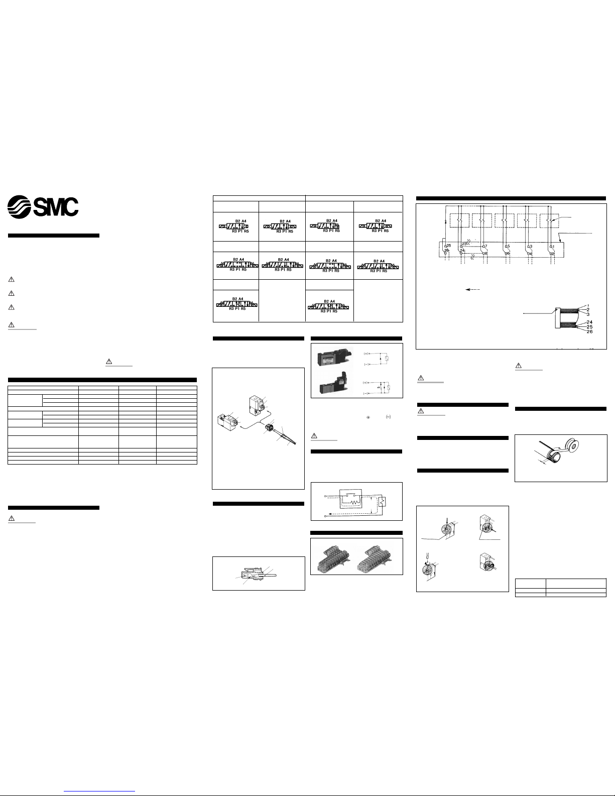
Flat cable manifold (Fig 7)
Note:Terminal numbers are not indicated on the connector.
The terminal numbers indicated on the connection schematic of connector,
as shown in the reference, means a correlation of 1,2, 3 .......26 from
the triangle mark side on the flat cable of connector.
12th station
A side
coil
Common (+)
( I ) A side coil
( I ) B side coil
{
{
( I ) A side coil
( I ) B side coil
{
( I ) A side coil
( I ) B side coil
{
( I ) A side coil
( I ) B side coil
{
( I ) A side coil
( I ) B side coil
{
Connected on the
printed board
B side
coil
A side
coil
B side
coil
A side
coil
B side
coil
A side
coil
B side
coil
A side
coil
B side
coil
4th station 3rd station 2nd station 1st station
Coil
Note) Connector
Triangle mark
indicated position
12th
station
(Max. 12 stations)
4th
station
3rd
station
2nd
station
1st
station
Triangle mark
Reference
• For manifolds of 5 stations or more both poles of the common should be wired.
• For single solenoid valves, connect to the B side coil.
Non-locking push type
Push in an arrow direction
Slotted locking type
Valve body
Pilot valve
Turn to the
direction of
arrow mark.
Push and turn. Can be used as
non-locking type if the
operator is just pushed without
turning.
Winding
direction
Seal tape
2 thread to be left exposed
VJ3000 4 port/5 port
VJ5000 VJ7000 5 port
2 position single
3 position closed centre
3 position exhaust centre
3 position pressure centre
2 position double
2 position single
3 position closed centre
3 position exhaust centre
3 position pressure centre
2 position double
Fig 1
When you enquire about the product, please contact the following
SMC Corporation:
ENGLAND Phone 01908-563888 TURKEY Phone 212-2211512
ITALY Phone 02-92711 GERMANY Phone 6103-402-0
HOLLAND Phone 020-5318888 FRANCE Phone 01-64-76-10-00
SWITZERLAND
Phone 052-396 31 31 SWEDEN Phone 08-603 07 00
SPAIN Phone 945-184100 AUSTRIA Phone 02262-62-280
Phone 902-255255 IRELAND Phone 01-4501822
GREECE Phone 01-3426076 DENMARK Phone 70 25 29 00
FINLAND Phone 09-68 10 21 NORWAY Phone 67-12 90 20
BELGIUM Phone 03-3551464 POLAND Phone 48-22-6131847
PORTUGAL Phone 02-610 8922
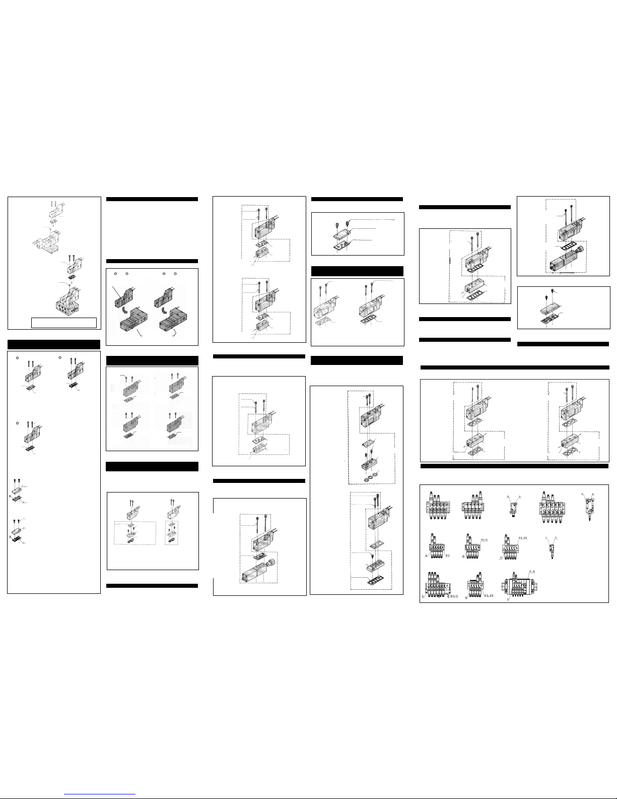
VJ7000 Accessories
Individual supply spacer (Fig 21)
An individual supply spacer complete with gasket may be fixed
between valve and subplate, so as to provide an individual pressure
supply to any valve.
Spacer type regulator (reducing P port pressure) (Fig 23)
Mounting a spacer type regulator between the valve and the manifold
makes it possible to reduce the supply pressure of every valve.
Blanking plate (Fig 24)
A blanking plate can be used to blank spare stations.
Environment
When valve is mounted in a control panel or is energised for long
periods of time, make sure the ambient temperature is within the
specified range.
Individual exhaust spacer (Fig 16)
An individual exhaust spacer complete with gasket may be fixed
between valve and subplate so as to provide an individual exhaust for
any valve.
Spacer type regulator (reducing P port pressure) (Fig 17)
Mounting a spacer type regulator between the valve and the manifold
makes it possible to reduce the supply pressure of every valve.
Blanking plate (Fig 18)
A blanking plate can be used to blank spare stations.
An adaptor plate makes it possible to mount series VJ700 3 port valves
and series VJ7000 valves on the same manifold.
For base mounted type,the A port of the 3 port valve is connected to
the B port on the manifold.
Manifold Mounting (Fig 10)
Mixed installation of 3 port-VJ300 and 5 port-VJ3000 on the same
manifold.
1. Type VV5J3-20, 21P Manifold.
Ensure that the redundant R port is occluded with rubber plug part
number VJ3000-33-1
2. Type VV5J-31, -S31, VV5J3-32, -S32, VV5J3-46, -S46, 32P
Manifolds.
In the case of the above manifolds the A port of the 3 port valve is
connected to the B port on the manifold.
3. Type VV5J3-41, -S41
As per 1. above,additionally the A port of the 3 port valve is
connected to the B port on the manifold.
Difference between VJ3000 Series 4 and 5 ported valves (Fig 12)
An adapter plate makes it possible to mount series VJ500 3 port
valves and series VJ5000 valves on the same manifold.
For base mounted type,the A port of the 3 port valve is connected to
the B port on the manifold.
VJ5000 accessories
Individual supply spacer (Fig 15)
An individual supply spacer complete with gasket may be fixed
between valve and subplate, so as to provide an individual pressure
supply to any valve.
VV5J3-20
(VJ300 3 port valve)
Plug (VJ3000-33-1)
Seal the no used R
port in the end cover
side on the base.
VV5J3-41
(VJ300 3 port valve)
Plug (VJ3000-33-1)
Seal the no used R
port in the end cover
side on the base.
"B" port is taken as A port of 3 way valve.
Fig 10
Fig 12
Fig 13
Fig 14
Fig 16
Fig 17
Fig 18
Fig 11
5 Port body ported type
(VJ3 2 )
0
3
4 Port Base Mounted type
(VJ3 3 )
0
3
A mark
A mark
Manifold
gasket
VJ3000-14-3
5 Port base
mounted type
(VJ3 4 )
0
3
A mark
Screws
M1.7x17
Manifold
gasket
VJ3000-14-1
Manifold
gasket
VJ3000-14-2
Applicable base
VV5J3-20, 21P
Manifold base
Applicable base
VV5J3-31
VV5J3-S31
VV5J3-32
VV5J3-S32
VV5J3-32P
}
Manifold base
Applicable base
VV5J3-41
VV5J3-S41
VV5J3-46
VV5J3-S46
}
Manifold base
Proper combination of blanking plate assembly and
manifold base
Blanking plate assembly
VJ3000-21-2A
Blanking plate assembly
VJ3000-21-2A
Blanking plate
VJ3000-21-1
Screws
M1.7x7
Blanking plate
VJ3000-21-1
Manifold gasket
VJ3000-14-1
Manifold gasket
VJ3000-14-3
Applicable base
VV5J3-20
Manifold base
Applicable base
Subplate
VV5J3-41
VV5J3-S41
VV5J3-46
VV5J3-S46
VV5J3-31
VV5J3-S31
VV5J3-32
VV5J3-S32
}
Note: Manifold gasket VJ300014-2 can be used with the
following manifold bases:
VV5J3-31
VV5J3-S31
VV5J3-32
VV5J3-S32
}
Manifold
base
Proper combination of VJ3000 Series solenoid valve,
gaskets and manifold (Fig 11)
Proper combination of VJ5000 Series solenoid valve,
gaskets and manifold (Fig 13)
Proper combination of VJ7000 Series solenoid valve,
gaskets and manifold (Fig 19)
Mixed installation of 3 port-VJ700 and 5 port-VJ7000 on
the same manifold (Fig 20)
Mixed installation of 3 port-VJ500 and 5 port-VJ5000 on
the same manifold (Fig 14)
Manifold
base
VJ3 30, 3 33
(4 Port)
VJ3 40, 3 43
(5 Port)
Steel ball is driven in.
Configuration of this
surface is different.
Screws
M2.5x25
(with spring
washer)
Gasket
DXT192-10-2
Gasket
DXT192-10-5
Gasket
DXT192-10-5
Gasket
DXT192-10-5
Applicable
base
VV5J5-20
Applicable
base
VV5J5-40
Applicable
base
Subplate
Applicable
base
VV5J5-41
VV5J5-42
VV5J5-43
Adapter plate assembly DXT200-3-1A
Series VJ500
Body ported type
Series VJ500
Base mounted type
Adapter plate assembly
DXT200-3-1A
Adapter plate
assembly
DXT200-3-1A
Manifold
gasket
DXT200-9-1
Screws
M2.5x9
Adapter plate
DXT200-3-1
Adapter gasket
DXT200-6-1
Applicable base
VV5J5-40
VV5J5-41
VV5J5-42
VV5J5-43
Applicable base
VV5J5-20
Individual SUP.spacer assembly
DXT192-40-1A
For M2.5
spring
washer
Screws
M2.5x40.5
For M2.5 spring
washer
Screws
M2.5x36
Base mounted type
P
Body ported type
Base mounted type
Gasket
DXT192-10-2
Gasket
DXT192-10-2
2-M5x0.8
(R1,R2 port)
Individual
SUP.spacer
DXT192-40-2
Individual
EXH.spacer
DXT192-21-1
1
/
8
(P port)
Applicable base
VV5J5-41
VV5J5-42
VV5J5-43
Fig 15
DXT192-40-2A
For M2.5
spring
washer
Screws
M2.5x40.5
Base mounted type
Gasket
DXT192-10-2
Individual
SUP.spacer
DXT192-40-2
Rc (PT) 1/
8
(P port)
Individual EXH. spacer assembly
DXT192-21-1A
ARBZ3000-00-P
Screws
M2.5x45
(with spring
washer)
Gasket
DXT192-10-5
Base mounted type
DXT192-13-1A
Screws
M2.5x7 (with spring washer)
Blanking plate
DXT192-13-2
Gasket
DXT192-10-2
Applicable manifold base
VV5J7-20
VV5J7-21
Applicable manifold base
VV5J7-40
VV5J7-41
VV5J7-42
Screws
M3x31
(with spring washer)
Screws
M3x31
(with spring washer)
Gasket
DXT199-21-4
Gasket
DXT199-21-7
Fig 19
Fig 21
Fig 23
Fig 24
Fig 20
Adapter plate assembly
DXT201-3-1A
Adapter plate assembly
DXT201-3-2A
Screws
M3x31
(with spring
washer)
Screws
M3x38
(with spring washer)
Screws
M3x31
(with spring
washer)
Series VJ7000
Body ported type
Gasket
DXT201-14-1
Screws AXT624-28
M3x10
(with spring washer)
Adapter plate
DXT201-3-1
"O" ring
12.5x9.5x1.5
Applicable
manifold base
VV5J7-20
VV5J7-21
Applicable
manifold base
VV5J7-40
VV5J7-41
VV5J7-42
Series VJ7000
Base mounted type
Adapter plate
DXT201-3-2
Gasket
DXT199-21-7
Applicable
manifold base
VV5J7-40
VV5J7-41
VV5J7-42
DXT199-35-1A
Screws
AXT623-14
M3x47
(with spring
washer)
Individual SUP spacer
DXT199-35-1
Gasket
DXT199-21-7
2-
1
/
8
(SUP port)
Base mounted type
R1
Screws
AXT623-14
M3x47
(with spring
washer)
2-
1
/
8
(Exhaust
holes)
Individual EXH spacer
DXT199-29-1
Gasket
DXT199-21-4
DXT199-29-1A
DXT199-29-2A
Screws
AXT623-14
M3x47
(with spring
washer)
2-
1
/
8
Exhaust
holes
Individual EXH spacer
DXT199-29-2
Gasket
DXT199-21-7
Applicable
manifold base
VV5J7-20
VV5J7-21
Applicable
manifold base
VV5J7-40
VV5J7-41
VV5J7-42
ARBZ5000-00-P
Screws
M3x55
(with spring
washer)
Base mounted type
Gasket
DXT199-21-7
DXT199-22-1A
Screws
VK300-33-3
M3x8
(with spring washer)
Blanking plate
DXT199-22-2
Gasket
DXT199-21-6
Screws
AXT624-28
M3x10
(with spring washer)
R1
R2
R2
R1
Applicable base
VV5J5-20
VV5J5-40
VV5J5-41
VV5J5-42
VV5J5-43
Applicable base
VV5J5-40
VV5J5-41
VV5J5-42
VV5J5-43
Mounting direction of base
There is a possibility that the base mount type VJ is mounted to base or sub-plate with the wrong direction.
Regarding collect direction, refer to the drawings shown below and check the symbol of valve and base.
Individual exhaust spacer (Fig 22)
An individual exhaust spacer complete with gasket may be fixed between valve and subplate,so as to provide an individual exhaust for any valve.
Fig 22
VV5J5-20/20P/40 type
VV5J3-20/41/S41 type VV5J3-S31/S32 type
VV5J3-S46 type
Subplate type
VV5J3-21P/31/32/32P type
VV5J3-46 type
VV5J3-35* type
VV5J5-41/41P/42/43/43P type
Subplate type
VV5J7-20/21/21P/40/41/42 type Subplate type
Applicable base
VV5J5-20
 Loading...