

SMC Networks VFS2100, VFS2200, VFS2300 Installation And Maintenance Manual
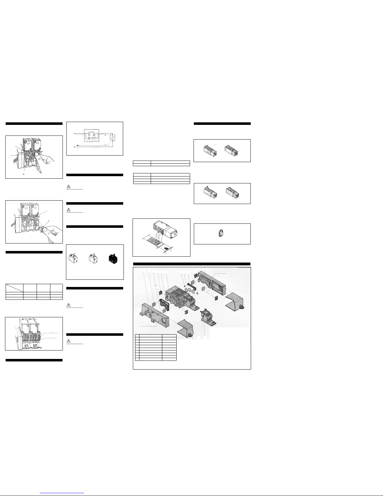
Wiring (Fig 4)
CAUTION
Isolate both power and air supplies before removing/replacing
connector.
In the case of DIN connector and terminal block (with lamp and surge
voltage suppressor), the internal wiring is shown in Fig 4.
1. Loosen the top screw and remove the connector housing from the
terminal spades on the solenoid.
2. Remove the housing screw and insert a screwdriver into the slot
on the underside of the DIN cap and carefully remove the block.
3. Loosen the terminal screws on the block and insert the stripped
leads. Secure each lead by re-tightening the appropriate terminal
screw.
4. Tighten the housing grommet nut to secure the cable.
CAUTION
Pull connector out vertically,never at an angle.
Wiring plug-in type (Fig 5)
Remove cover 1 (Fig. 6) on subplate to expose terminal block 2
(Fig. 6).
The terminal block is marked as follows:-
Designation Solenoid Solenoid
A-side B-side
Terminal block board A B
Marking
• Note: Non polar
Lead wire wiring/manifold/plug-in type
Type 01 insert plug with lead wire
Series VFS2000 (only VFS2000)
How to remove junction cover (type 01 Fig 7)
Turn the knob 2 of junction cover 1 on the manifold block side by
hand or slotted screwdriver to the C R O direction (counter clockwise)
90°.While holding the knob and upper part of junction cover, pull outward to remove junction cover.When reassembling, do the opposite.
Wiring (Fig 8)
The insert plug 1 is attached to the manifold block and lead wire is
plugged in with valve side as shown in the following list:
Single solenoid
Double solenoid
Please connect with corresponding power side.
AC power/lead wire colour identification
Solenoid A side B side
Lead wire colour Red,black -
DC power/lead wire colour identification
Solenoid A side B side
Lead wire colour Red Black Brown White
• Lead wire length is 1m.
• No polarity.
Installation and Maintenance Manual
Series VFS2000 5 Port Metal Seal Type Solenoid Valves
This manual should be read in conjunction with the current catalogue
For future reference, please keep this manual in a safe place
Safety Instructions
These safety instructions are intended to prevent a hazardous situation and/or equipment damage.These instructions indicate the level
of potential hazard by label of “Caution”,“Warning” or “Danger”.
To ensure safety,be sure to observe ISO4414
(Note1)
, JIS B 8370
(Note2)
and other safety practices.
Note 1: ISO 4414:Pneumatic fluid power – Recommendations for the
application of equipment to transmission and control systems.
Note 2: JIS B 8370: Pneumatic system axiom.
CAUTION : Operator error could result in injury or
equipment damage.
WARNING: Operator error could result in serious
injury or loss of life.
DANGER : In extreme conditions, there is a
possible result of serious injury or loss of life.
WARNING
1. The compatibility of pneumatic equipment is the responsibility of the person who designs the pneumatic system
or decides its specifications.
Since the products specified here are used in various operating
conditions, their compatibility for the specific pneumatic system
must be based on specifications or after analysis and/or tests to
meet your specific requirements.
2. Only trained personnel should operate pneumatically
operated machinery and equipment.
Compressed air can be dangerous if an operator is unfamiliar
with it. Assembly, handling or repair of pneumatic systems should
be performed by trained and experienced operators.
3. Do not service machinery/equipment or attempt to
remove component until safety is confirmed.
1) Inspection and maintenance of machinery/equipment should
only be performed after confirmation of safe locked-out
control positions.
2) When equipment is to be removed, confirm the safety process
as mentioned above.Switch off air and electrical supplies and
exhaust all residual compressed air in the system.
3) Before machinery/equipment is re-started, ensure all safety
measures to prevent sudden movement of cylinders etc.
(Bleed air into the system gradually to create back-pressure,
i.e. incorporate a soft-start valve).
4. Contact SMC if the product is to be used in any of the
following conditions:
1) Conditions and environments beyond the given specifica-
tions, or if product is used outdoors.
2) Installations in conjunction with atomic energy, railway, air
navigation, vehicles,medical equipment, food and beverage,
recreation equipment, emergency stop circuits, press
applications, or safety equipment.
3) An application which has the possibility of having negative
effects on people, property, or animals, requiring special
safety analysis.
CAUTION
Ensure that the air supply system is filtered to 5 micron.
Standard specifications
Fluid Air and inert gas
Max. operating pressure 9.9 kgf/cm2(990kPa)
Min. operating 2 position 1.0 kgf/cm2(100kPa)
pressure 3 position 1.5 kgf/cm2(150kPa)
Valve Ambient and fluid temperature Note 1:-10~+60°C
Lubrication Note 2: Not required
Pilot operator manual override Non-locking push type (flush type)
Protection structure Dust proof
Rated voltage AC 100, 200V (50/60Hz)
DC 24V
Allowance voltage range -15~+10% rated voltage
Coil insulation Class B or equivalent
Electricity Apparent power
Inrush 5.0VA/60Hz, 5.6VA/50Hz
(Power AC
consumption)
Holding 2.3VA (1.5W)/60Hz, 3.4VA (2.1W)/50Hz
Power consumption DC 1.8W
Electrical entry Grommet,Grommet terminal
Conduit terminal, DIN connector
Note 1: Use dry-air at low temperature.
Note 2: Use turbine oil No.1 (ISO VG 32), if lubricated.
032a/eng
Installation
WARNING
Ensure all air and power supplies are ISOLATED before commencing
installation.
Do not install these valves in explosive atmospheres.
If these valves are exposed to water or oil droplets, ensure that they
are protected.
If it is intended to energise a valve for an extended period please consult SMC.
If air leakage causes associated equipment to malfunction cease using
valve and inspect for cause.
Check fixings while pressure and power are applied. Initial function
and leakage tests should be performed after installation.
Only install once safety instructions have been read and understood.
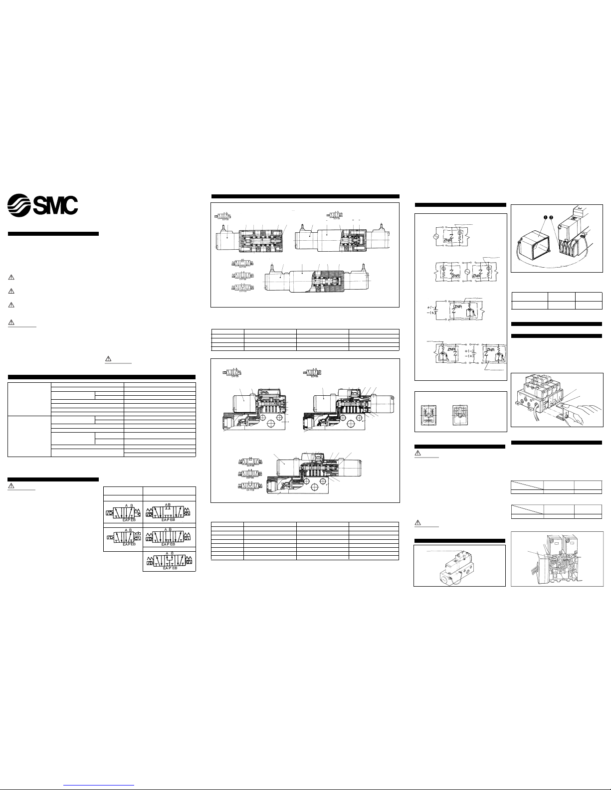
Symbol
2 position
Single
Double
Exhaust centre
Pressure centre
Closed centre
3 position
Construction and parts (Fig 1)
2 position single
2 position double
3 position closed centre/exhaust centre/pressure centre
6
6
6 21 5 4
2
1
7
4
4
2
1
5
3
Closed centre
Pressure centre
Exhaust centre
Fig 1
Fig 2
Fig 5
Main parts
No. Description Material Note
1 Body Aluminum die-cast Platinum silver
2 Spool/sleeve Stainless steel -
3 End plate Resin -
4 Piston Resin -
Body Ported type
2 position single
2 position double
3 position closed centre/exhaust centre/pressure centre
M
6
8
8
3
3
9
5
1
2
M
M
K
K
8
3 4
4 9
6
6
2
2K1
J
1
L
7
7
7
J
Closed centre
Pressure centre
Base mounted type
Exhaust centre
Main parts
No. Description Material Note
1 Body Aluminum die-cast Platinum silver
2 Sub plate Aluminum die-cast Platinum silver
3 Spool/sleeve Stainless steel -
4 Adapter plate Aluminum die-cast Platinum silver
5 Endplate Resin Black
6 Piston Resin -
7 Junction cover Resin -
8 Light cover Resin -
Fig 3
Fig 6
Fig 7
Fig 4
Electrical connection body ported type
Lamp and surge voltage suppressor (Fig 3)
AC and 100VDC
24VDC or less
Single
Double
Double
Terminal No.1(+)
Terminal No.1+(-)
Terminal No.2-(+)
Note: No polarity.
Terminal No.2-(+)
Note: No polarity.
With light
Terminal
No. 2-(+)
B side terminal No. 1+(-)
With light
Terminal No.1+(-) A side
Terminal No.2 (-)
Terminal No.2 (-)
Terminal No.2 (-)
B side terminal No. 1(+)
With light
Terminal
No. 1(+)
With light
A side
With light
Single
Applicable terminals :
1.25-3, 1.25-3S,1.25Y-3N
or 1.25Y3S. Not required
for DIN connector board.
With terminal
block board
With DIN
connector board
Note: No polarity
With indicator light and surge
voltage suppressor
Plug-in type
Fig 8
2
1
1
as to occlude exhaust galleries. Perfect spacer
When fixed between a valve with built in double check valves and subplate the perfect spacer can hold an actuator in a desired position anywhere along it's stroke for a considerable period of time.
Environment
When valve is mounted in a control panel or is energised for long
periods of time, make sure the ambient temperature is within the
specified range.
When used in temperatures higher than 60° please contact SMC.
How to use insert plug (Fig 9, 10)
When removing insert plug 1 from manifold base,push the lever area
2 of insert plug downward with thumb and pull it together with the
lead wire 3 out.
When plugging the insert plug 1 into the manifold base, push the
lever area of insert plug with thumb and plug it in its place in the
receptacle housing 4 horizontally.
After plugging, pull lead wire out a little bit to ensure that insert plug
is secure.
Type 01T with terminal block board (Fig 11)
Series VFS2000
Remove junction cover of manifold, exposing terminal block board
attached to the manifold block. Lead wires from solenoid valve are
connected with the terminals on upper side of terminal block board.
(On the terminal block board, lead wire is connected with both A and
B sides of solenoid valve in accordance with the corresponding markings A and B on the block board.)
Connect each lead wire of power side corresponding to each respective solenoid valve on the lower terminal block board.
Terminal block wiring specification is in accordance with +COM.
Block board
marking
Model
A COM B
VFS2100 A side COM B side
VFS2200 A side COM B side
VFS2300 A side COM B side
• Applicable terminal: 1.25-3, 1.25-3S,1.25Y-3N, 1.25Y-3S
• Plugging COM bridge (Part No. AXT625-73) in between each
+COM on the block board will make the specifications of all the
stations +COM and enables you to rationalise the wiring process.
• No polarity.
Leakage voltage (Fig 12)
Note that when using a C-R device (surge voltage suppressor) for
contact protection, the voltage leakage may increase due to the
current leakage flowing through the C-R device.
Suppress residual voltage leakage as follows:
DC Coil 3% or less of rated voltage
AC Coil 20% or less of rated voltage
Lubrication
These valves have been lubricated for life during manufacture and as
such require no further lubrication.
CAUTION
However,if a lubricant is to be used with a rubber seal type, a turbine
oil type #1,(ISO VG32) should be used, continuous lubrication must be
carried out as the original lubricant will be washed away.
Manual override operation (Fig 13)
WARNING
Exercise EXTREME CAUTION when operating a solenoid manual
override as connected equipment will commence operation.
Ensure all safety measures are in place.
Non-locking push type (Fig 13, 13a)
1. Push down the manual override button (Orange), until it stops,
using a small-bladed screwdriver.
2. Hold this position for the duration of the check (ON position)
3. Release the button and the override will re-set to the OFF
position.
Slotted locking type (Fig 13b)
To lock
1. Insert a small-bladed screwdriver into the slot.
2. Turn the override through 90° (ON position).
3. Remove screwdriver
WARNING
In this position the manual override is in the locked 'ON' position.
To unlock
1. Insert small-bladed screwdriver into the slot of the manual
override.
2. Turn the screwdriver 90° in the reverse direction.
3. Remove the screwdriver, the manual override will re-set to the
'OFF' position.
Maintenance
WARNING
Ensure air and electrical supplies are isolated before commencing any
maintenance work.
1. The ingress of carbon and oil present in the air supply (mostly
from the compressor) into the valve can sometimes lead to
increased resistance between the spool and sleeve. In the worst
case it can lead to the spool adhering to the sleeve.Therefore it is
important to check the quality of the air often.
In order to minimise the risk of the above,it is recommended that
a Mist Separator (Series AM) is installed upstream of the valve
after a Standard Filter (Series AF).Also selecting a compressor oil
with minimal oxidisation characteristics would elevate any such
problems.
2. Should the valve and sleeve adhere to each other then disassemble the valve and clean the assembly in a solvent based chemical
taking care not to contaminate any O-rings with cleaning agent.
Mounting
When disassembling and reassembling ensure that all components are
in their proper positions. Prevent gaskets from moving and torque
screws down equally.
Pilot operator assembly: SF4-u-u
Set screw Correct clamping torque kgf-cm (N-m)
M3 4.5~6(0.45~0.6)
Solenoid valve body
Set screw Correct clamping torque kgf-cm (N-m)
M3 6~10(0.6~1)
M4 14~25(1.4~2.5)
M5 28~50(2.8~5)
Single solenoid operated valves may be mounted in any attitude.However,
in environments that subject the valves to vibration double solenoid operated valves should be aligned perpendicular to the vibration.
Never use in conditions where vibrations exceed 5G.
How to remove/replace base mounted type
1. Loosen 3 set screws (hexagonal socket head cap screws M3x31)
and pull solenoid valve out vertically. Failing to do so may result
in damage to the solenoid valve.
2. When mounting solenoid valve on to the base, engage plug
(underside of valve) and socket (top face of base) before replacing and tightening screws.
Accessories
Individual supply spacer
An individual supply spacer complete with gasket may be fixed
between valve and subplate so as to provide an individual pressure
supply to any valve.
Individual exhaust spacer
An individual exhaust spacer complete with gasket may be fixed
between valve and subplate so as to provide an individual exhaust for
any valve.
Exhaust block disk
If valve exhaust affects the function of other valves on the manifold
then an exhaust block disks may be fitted between the sub plates so
as to occlude exhaust galleries.
Fig 9
Fig 10
Fig 13a,b
Fig 15
Fig 14
Fig 11
Fig 12
Switching element
Leakage current
Leakage
current
Source
Valve
OFF
Wiring area
Markings
* Special order.
Non-locking push
type (flush type)
*A - Non-locking push
type (extended type)
*B - Lock type
(tool type)
a b
K 2
M
1
3
J 7
5
4
6
L
89
Parts list
No. Description Material
1 Metal joint A Steel plate
2 Metal joint B Steel plate
3 Gasket A NBR
4 Gasket B NBR
5 O-ring NBR
6 O-ring NBR
7 O-ring NBR
8 Terminal assembly -
9 Junction cover assembly -
End plate (D side)
End plate (U side)
For increasing the manifold bases,please prepare the manifold block assembly No.of the
principal part assembly J.
Plug-in type:The manifold base with terminal
stand (integral type with a junction cover) is
required with the 9 junction cover assembly.
Note: Manifold base/construction: Plug-in type
with terminal block board.
Manifold base construction/plug-in type/non plug-in type (Fig 15)
Fig 16
Fig 17
Fig 18
When you enquire about the product, please contact the following
SMC Corporation:
ENGLAND Phone 01908-563888 GERMANY Phone 6103-402-0
ITALY Phone 02-92711 FRANCE Phone 1-64-76-10-00
HOLLAND Phone 020-5318880 SWEDEN Phone 08-603-07-00
SWITZERLAND
Phone 052-34-0022 AUSTRIA Phone 02262-62-280
SPAIN Phone 945-290600 IRELAND Phone 01-4501822
GREECE Phone 01-3426076 DENMARK Phone 8738-0800
FINLAND Phone 9-68-10-21 NORWAY Phone 67-12-90-20
BELGIUM Phone 03-3551464 POLAND Phone 48-22-6131847
TURKEY Phone 212-2211512
2
1
3
4
1
 Loading...