

THERMO-CON HEC001 Series,THERMO-CON HEC003 Series,THERMO-CON HEC012 Series,THERMO-CON HEC006 Series,THERMO-CON HEC002 Series
SMC Networks THERMO-CON HEC001 Series,THERMO-CON HEC003 Series,THERMO-CON HEC012 Series,THERMO-CON HEC006 Series,THERMO-CON HEC002 Series Communications Manual
サーモコン
HEC002-A
THERMO-CON
Model No.
HEC001 series
HEC003 series
HEC012 series
HEC002 series
HEC006 series
Keep available whenever necessary.
A_HEC-OM-J017
Rev.May.2010
© 2006 SMC CORPORATION All Rights Reserved
This manual is copyrighted and all rights are reserved by SMC
Corporation, and may not, in whole or in part, be copied,
photocopied or translated without prior written consent of SMC.

History
HEC i
History
Version
Preface
Contents
Chap.1
Chap.2
Chap.3
Chap.4
Chap.5
Chap.6
1.0
1.1
Record of Changes
Version
Contents
Date
1.0
First edition
June.2006
1.1
The series name is added to the cover.The product photography of the
cover is deleted.
May.2010

Preface
HEC
ii
Preface
Thank you very much for purchasing SMC Thermo-con.
This manual contains description for communication of this product for your full benefit from this product.
Read the operation manual carefully before use of this product, and understand the outline of the
product and safety instructions well. Instructions in the categories, “Danger”, “Warning” and “Caution”,
are important for safety and must be duly followed.
Please contact the following for any question and unclear points regarding the Thermo-con.
SMC Corporation R&D Center
Product Development Division-6
Address: 4-2-2, KINUNODAI,TSUKUBAMIRAI-CITY , IBARAKI-KEN 300-2493, JAPAN
Phone:+81-297-52-6666
Fax:+81-297-20-5007
E-mail:kaihatsu_6_g3@smcjpn.co.jp
Notice: The content of this manual can be revised without a previous notice.

CONTENTS
HEC iii
CONTENTS
Pages
1 Preparation for Communication ------------------------------------------------- 1-1
2 Specifications of Communication Method ----------------------------------- 2-1
3 Communication Format ------------------------------------------------------------- 3-1
3.1 Control code used for communication -------------------------------------------------------------- 3-1
3.2 Command code list --------------------------------------------------------------------------------------- 3-1
3.3 Communication procedures and format ------------------------------------------------------------ 3-2
3.4 Calculation of checksum -------------------------------------------------------------------------------- 3-3
4 Details of Communication format ----------------------------------------------- 4-1
4.1 Temperature setting (without writing EEPROM) -------------------------------------------------- 4-1
4.2 Reading setting temperature --------------------------------------------------------------------------- 4-1
4.3 Reading internal sensor --------------------------------------------------------------------------------- 4-2
4.4 Reading external sensor -------------------------------------------------------------------------------- 4-3
4.5 Reading alarm status ------------------------------------------------------------------------------------ 4-3
4.6 Reading temperature average data ------------------------------------------------------------------ 4-5
4.7 Offset setting (without writing EEPROM) ----------------------------------------------------------- 4-5
4.8 Reading offset --------------------------------------------------------------------------------------------- 4-5
4.9 Temperature setting (with writing EEPROM) ------------------------------------------------------ 4-6
4.10 Offset setting (with writing EEPROM) --------------------------------------------------------------- 4-7
5 Troubleshooting ----------------------------------------------------------------------- 5-1
6 Communication Format and
Examples of Answers from Thermo-con -------------------------------- 6-1

Preparation for Communication
HEC 1-1
1 Preparation for Communication
Make preparation for using communication facility as follows.
1) Turn off the power switch of Thermo-con.
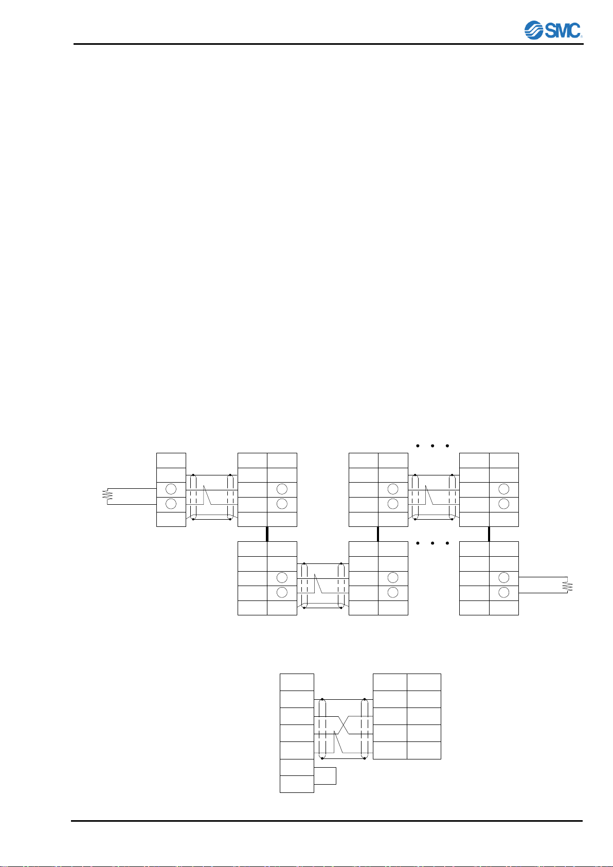
2) Connect communication cable to communication connector (RS-485 of RS-232C) of Thermo-con.
・Use twist pair shield cable as communication cable.
・Connect the host and thermo-con with the cross cable for RS-232C and the straight cable for RS-485.
・Connect shielded cable of communication cable to communication connector and drop it to FG(flame
ground).
・Connection drawing for communication is shown in the Figures 1-1 and 1-2.
・Length of communication cable for RS-485 shall be limited to around 500[m] in total, and that for RS-
232C shall be 15[m].
・If communication cable for RS-485 is longer, connect terminating resistance (220Ω,1/2w) to each +
and - terminal of the host computer and the farthest Thermo-con.
3) Turn on the power switch of Thermo-con.
4) Select communication types for all Thermo-cons. See the operation manual of the details.
5) That’s all for preparation of communication. Then if a communication command from the host
computer is given, each Thermo-con will reply it.
Figure1-2 Communication Connection (RS-232C)
Host Computer
RS-232C
Symbol
FG
RD
SD
SG
Thermo-con
RS-232C
RS
CS
Short
Pin No.
Connector
shell
2
3
5
Symbol
FG
RD
SD
SG
Figure1-1 Communication Connection (RS-485)
Host Computer
RS-485
Thermo-con No.1
RS-485
Thermo-con No.2
RS-485
Thermo-con No.3
RS-485
Internal connection
Terminating
resistance
220Ω1/2W
Terminating
resistance
220Ω1/2W
Internal connection Internal connection
Pin No.
Connector
shell
1
2
5
FG
+
-
SG
SymbolPin No.
Connector
shell
1
2
5
FG
+
-
SG
SymbolPin No.
Connector
shell
1
2
5
FG
+
-
SG
Symbol
Pin No.
Connector
shell
1
2
5
FG
+
-
SG
Symbol Pin No.
Connector
shell
1
2
5
FG
+
-
SG
Symbol Pin No.
Connector
shell
1
2
5
FG
+
-
SG
Symbol
Symbol
FG
+
-
SG
Thermo-con No.16

 Loading...