

SMC Networks SYJ300, SYJ700, SYJ500 Installation And Maintenance Manual
Installation and Maintenance Manual
Series SYJ300/500/700 Solenoid Valve (3 Port)
This manual should be read in conjunction with the current valve catallogue
For future reference, please keep this manual in a safe place
Safety Instructions
These safety instructions are intended to prevent a hazardous situation and/or equipment damage.These instructions indicate the level
of potential hazard by label of “Caution”,“Warning” or “Danger”.
To ensure safety,be sure to observe ISO4414
(Note1)
, JIS B 8370
(Note2)
and other safety practices.
Note 1: ISO 4414:Pneumatic fluid power – Recommendations for the
application of equipment to transmission and control systems.
Note 2: JIS B 8370: Pneumatic system axiom.
CAUTION : Operator error could result in injury or
equipment damage.
WARNING: Operator error could result in serious
injury or loss of life.
DANGER : In extreme conditions, there is a
possible result of serious injury or loss of life.
WARNING
1. The compatibility of pneumatic equipment is the responsibility of the person who designs the pneumatic system
or decides its specifications.
Since the products specified here are used in various operating
conditions, their compatibility for the specific pneumatic system
must be based on specifications or after analysis and/or tests to
meet your specific requirements.
2. Only trained personnel should operate pneumatically
operated machinery and equipment.
Compressed air can be dangerous if an operator is unfamiliar
with it.Assembly, handling or repair of pneumatic systems should
be performed by trained and experienced operators.
3. Do not service machinery/equipment or attempt to
remove component until safety is confirmed.
1) Inspection and maintenance of machinery/equipment should
only be performed after confirmation of safe locked-out
control positions.
2) When equipment is to be removed, confirm the safety process
as mentioned above.Switch off air and electrical supplies and
exhaust all residual compressed air in the system.
3) Before machinery/equipment is re-started, ensure all safety
measures to prevent sudden movement of cylinders etc.
(Bleed air into the system gradually to create back-pressure,
i.e. incorporate a soft-start valve).
4. Contact SMC if the product is to be used in any of the
following conditions:
1) Conditions and environments beyond the given specifica-
tions, or if product is used outdoors.
2) Installations in conjunction with atomic energy, railway, air
navigation, vehicles,medical equipment, food and beverage,
recreation equipment, emergency stop circuits, press
applications, or safety equipment.
3) An application which has the possibility of having negative
effects on people, property, or animals, requiring special
safety analysis.
CAUTION
Ensure that the air supply system is filtered to 5 micron.
SYJ300/500/700 Series Common Solenoid Specifications
Solenoid specifications
Electrical entry Grommet (G) · (H), L type plug connector (L),
M type plug connector (M)
Coil rated voltage V DC 24, 12, 6,5, 3
Allowable voltage ±10% rated voltage
Power consumption W
Note)
DC 0.5 (with light: 0.55)
Surge voltage suppressor Diode
Indicator light LED
SYJ300 Series (Fig 1a, b)
Model
Valve model Type Port Effective Weight g
of size mm
2
(Cv)
Grommet
L type plug connector,
actuation
M type plug connector
Body ported type SYJ312 N.C.
M3x0.5 0.9 (0.05) 29 31
SYJ322 N.O.
Base mounted type SYJ314 N.C.
M5x0.8 1.8 (0.1)
50 52
(with sub-plate) SYJ324 N.O.
(without sub-plate 29) (without sub-plate 31)
Valve specifications
Fluid Air
Operating pressure range
Internal pilot 0.15~0.7 (1.5~7.1)
MPa (kgf/cm2)
Ambient and fluid temperature °C Max.50
Response time ms (at 0.5MPa [5.1 kgf/cm2])
Note 1
15 or less
Max. operating frequency Hz 10
Manual override Non-locking push type, push-locking slotted type
Pilot exhaust
Individual pilot exhaust type. Common exhaust (pilot and main valve) type
Lubrication Not required
Mounting position Free
Impact/vibration resistance m/s
2
150/30
Note 1)
Protection structure IP40
Note: Impact resistance: There should be no malfunction of the valve after testing, using a drop impact tester,along the valve axis and at right
angles to the valve and armature.Carry out each test with the valve energised and de-energised.
Vibration resistance:There should be no malfunction of the valve after testing, using an 8,3 to 2000Hz sweep,along the axis and at right
angles to the valve and armature.Carry out each test with the valve energised and de-energised.
SYJ700 Series (Fig 3a, b)
Model
Valve model Type Port Effective Weight g
of size mm
2
(Cv)
Grommet
L type plug connector,
actuation
M type plug connector
Body ported type SYJ712 N.C.
Rc (PT)
1
/80.9 (0.05) 72 74
SYJ722 N.O.
Base mounted type SYJ714 N.C. Rc (PT) 1/
8
0.9 (0.05)
132 134
(with sub-plate) SYJ724 N.O. Rc (PT) 1/
4
(without sub-plate 72) (without sub-plate 74)
Valve Specifications
Fluid Air
Operating pressure range
Internal pilot 0.15~0.7 (1.5~7.1)
MPa (kgf/cm2)
Ambient and fluid temperature °C Max.50
Response time ms (at 0.5MPa [5.1 kgf/cm2])
Note 1
30 or less
Max. operating frequency Hz 5
Manual override Non-locking push type, push-locking slotted type
Pilot exhaust
Individual pilot exhaust type. Common exhaust (pilot and main valve) type
Lubrication Not required
Mounting position Free
Impact/vibration resistance m/s
2
150/30
Note 1)
Protection structure IP40
Note: Impact resistance: There should be no malfunction of the valve after testing, using a drop impact tester,along the valve axis and at right
angles to the valve and armature.Carry out each test with the valve energised and de-energised.
Vibration resistance:There should be no malfunction of the valve after testing, using an 8,3 to 2000Hz sweep,along the axis and at right
angles to the valve and armature.Carry out each test with the valve energised and de-energised.
036a/eng
Installation
CAUTION
Ensure all air and power supplies are ISOLATED before commencing
installation.
WARNING
DO NOT INSTALL THESE VALVES IN EXPLOSIVE ATMOSPHERES.
If these valves are exposed to water or oil droplets, ensure that the
valves are protected.
If it is intended to energise a valve for an extended period please
consult SMC.
SYJ300 Series (Fig 1a)
Fig 1a
Fig 2b
Fig 1b Fig 2a
Internal pilot
External pilot
Manifold Specifications
Type For internal pilot Type 20 Type 41,S41 Type 42,S42
For external pilot Type 20R - Type 42R,S42R
Manifold type Single base type /B mount
P(SUP) · R(EXH) type Common SUP · Common EXH
Valve stations 2-20 stations
A port specifications
Location Valve Base
Direction Top Side
Port size
P,R port
M5x0.8
M5x0.8 Rc(PT)
1
/
8
Rc(PT)
1
/
8
M5x0.8
A port M3x0.5 M3x0.5
C4 (ø4 one-touch fitting)
X port
Note 1)
M5x0.8 - M5-0.8
Note 2
Body ported type
0.9 (0.05) -
Valve effective area SYJ 2/SYJ3 2R
mm
2
(Cv) Base mounted type
- 1.5 (0.08)
SYJ3 4/SYJ3 4R
Note 1: Only for external pilot
Note 2:Value when used on a manifold
Manifold Specifications
Type
For internal pilot Type 20 Type 40 Type 41
For external pilot Type 21R Type 40R Type 41R
Manifold type Single base type /B mount
P(SUP) · R(EXH) type Common SUP · Common EXH
Valve stations 2-20 stations
A port specifications
Location Valve Base
Direction Top Bottom Side
Port size
P,R port Rc(PT)
1
/
8
Rc(PT)
1
/
8
Rc(PT)
1
/
8
M5x0.8, Rc(PT)
1
/
8
A port M5x0.8
M5x0.8
C4 (ø4 one-touch fitting)
Rc(PT)
1
/
8
C6 (ø6 one-touch fitting)
X port
Note 1)
M5x0.8 M5x0.8 M5x0.8
Body ported type
3.4 (0.19) -
Note 2
SYJ5 2/SYJ5 2R
Valve effective area Base mounted type - M5: 3.8 (0.21) M5: 3.3 (0.18)
mm
2
(Cv) SYJ5 4/SYJ5 4R
1
/
8
: 4.7 (0.26)
1
/
8
: 4.8 (0.27)
C4, C6 : 3.8 (0.21)
Note 1: Only for external pilot
Note 2:Value when used on a manifold
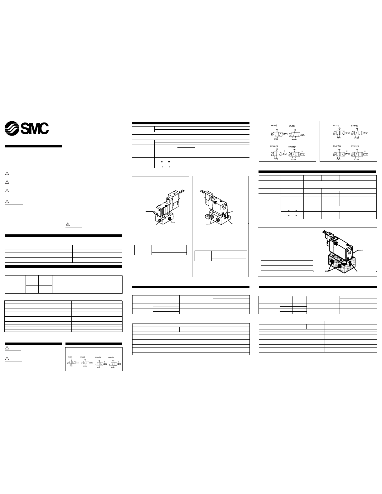
SYJ500 Series (Fig 2a, b)
Model
Valve model Type Port Effective Weight g
Note)
of size mm2(Cv)
Grommet
L type plug connector,
actuation
M type plug connector
Body ported type SYJ512 N.C.
M5x0.8 3.6 (0.2) 43 45
SYJ522 N.O.
Base mounted type SYJ514 N.C.
Rc(PT)
1
/
8
4.5 (0.25)
57 59
(with sub-plate) SYJ524 N.O.
(without sub-plate 43) (without sub-plate 45)
Valve Specifications
Fluid Air
Operating pressure range
Internal pilot 0.15~0.7 (1.5~7.1)
MPa (kgf/cm2)
Ambient and fluid temperature °C Max.50
Response time ms (at 0.5MPa [5.1 kgf/cm2]) 25 or less
Max. operating frequency Hz 5
Manual override Non-locking push type, push turn-locking slotted type
Pilot exhaust
Individual pilot exhaust type. Common exhaust (pilot and main valve) type
Lubrication Not required
Mounting position Free
Impact/vibration resistance m/s
2
150/30
Note 1)
Protection structure IP40
Note: Impact resistance: There should be no malfunction of the valve after testing, using a drop impact tester,along the valve axis and at right
angles to the valve and armature.Carry out each test with the valve energised and de-energised.
Vibration resistance:There should be no malfunction of the valve after testing, using an 8,3 to 2000Hz sweep,along the axis and at right
angles to the valve and armature.Carry out each test with the valve energised and de-energised.
Internal pilot
External pilot
Fig 3a
Fig 3b
Internal pilot
External pilot
External pilot type
SYJ300R
External pilot type
SYJ500R
Specifications
Applicable model
Base mounted type
(SYJ314R, SYJ324R)
Operating pressure Main pressure
-100kPa~0.7{10 torr~7.1}
range MPa {kgf/cm2} External pilot pressure 0.15~0.7{1.5~7.1}
P,R port
M5x0.8
A port
M5x0.8
X port (external pilot)
M5x0.8
Note: Externally piloted body ported valves (SYJ3k2R) can
only be used on the manifold.
Specifications
Applicable model
Base mounted type
(SYJ514R, SYJ524R)
Operating pressure Main pressure
-100kPa~0.7{10 torr~7.1}
range MPa {kgf/cm2} External pilot pressure 0.15~0.7{1.5~7.1}
Note: Externally piloted body ported valves (SYJ5k2R) can
only be used on the manifold.
For body ported models with the external pilot option
contact SMC.
P,R port
Rc(PT)1/8
A port
Rc(PT)1/8
X port
(external pilot)
M5x0.8
X port (external pilot)
M5x0.8
P,R port
Rc(PT)
1
/8,1/
4
A port
Rc(PT)
1
/8,1/
4
External pilot type
SYJ700R
Note: Externally piloted body ported valves (SYJ7k2R) can
only be used on the manifold.
For body ported models with the external pilot option contact
SMC.
Specifications
Applicable model
Base mounted type
(SYJ714R, SYJ724R)
Operating pressure Main pressure
-100kPa~0.7{10 torr~7.1}
range MPa {kgf/cm2} External pilot pressure 0.15~0.7{1.5~7.1}
CAUTION
Leakage voltage
When a C-R device (surge voltage suppressor) is used for the
protection of the switching device,be aware that leakage voltage will
be increased by passing this leakage through a C-R device.
Suppress residual leakage voltage as follows:
DC coil: 3% or less of rated voltage
Solenoid manual override (Fig 8 and Fig 9)
WARNING
Exercise extreme CAUTION when operating solenoid manual overrides
as connected equipment will commence operation.
Push non-locking type (Fig 8)
1 Push down on the manual override button (Fig 8) until it stops ON.
2 Hold this position whilst carrying out function checks.
3 Release the manual override button and the override will re-set to
the OFF position.
Push locking type (Fig 9)
1 Push down and turn the manual override button (Fig 9) clockwise
using a small slotted screwdriver until the slot is opposite the
locked position.
2 Withdraw the screwdriver.
WARNING
In this position the manual override is mechanically locked ON.
Unlocking (Fig 9)
1 Insert screwdriver into the override slot, push down and turn anti-
clockwise until the slot is opposite the unlock position.
2 Remove the screwdriver and the manual override will re-set to the
OFF position.
Maintenance
WARNING
Before carrying out any form of maintenance ensure all air and power
supplies are isolated.
Removing a valve from the base (Fig 10)
1 Disconnect the electrical connector 1 (Fig 10) (Also refer to Fig 6).
2 Remove the valve holding down screws 2 and retain) (Fig 10) .
3 Lift off the valve from the base.
4 Retain the gasket 3 (Fig 10) .
Refitting a valve to a base
1 Refit the gasket 3 (Fig 10) ensuring correct orientation.
2 Replace the valve.
3 Refit the valve holding down screws 2 (Fig 10).
4 Torque the screws to the following figures:
SYJ300 0.12 N-m {1.2 kgf/cm}
SYJ500 0.45 N-m { 4.5 kgf/cm}
SYJ700 0.8 N-m { 8.0 kgf/cm}
Fitting blanking plate (Fig 11)
1 Remove valve as shown above (Fig 10).
2 Fit blanking plate gasket 3 (Fig 11) .
3 Fit blanking plate 2 Fig 11).
4 Fit blanking plate holding down screws 1 (Fig 11).
5 Torque the screws to the following figures:
SYJ300 0.12 N-m { 1.2 kgf/cm}
SYJ500 0.45 N-m { 4.5 kgf/cm}
SYJ700 0.8 N-m {8.0 kgf/cm}
Piping
Clamping torque
Thread Correct clamping torque N-m (kgf-cm)
Rc(PT)1/8 7~9 (70~90)
Rc(PT)1/4 12~14 (120~140)
Lubrication
The valve has been lubricated for life at manufacture and requires no
additional lubrication.
CAUTION
However,if a lubricant is to be used, a turbine oil type #1 (ISO VG32)
should be used. If a lubricant is used, continuous lubrication must be
carried out, as the original lubricant will be washed away.
Energisation time
The double solenoid valve must be energised for at least 0.05 seconds
to ensure proper operation.Low
Low temperature application
May be used down to -10° if the air is sufficiently free of moisture.
Please use an appropriate dryer to ensure dry air preventing the valve
from freezing.
Energising in a long run
For use of long run energising, its specifications should be consulted.
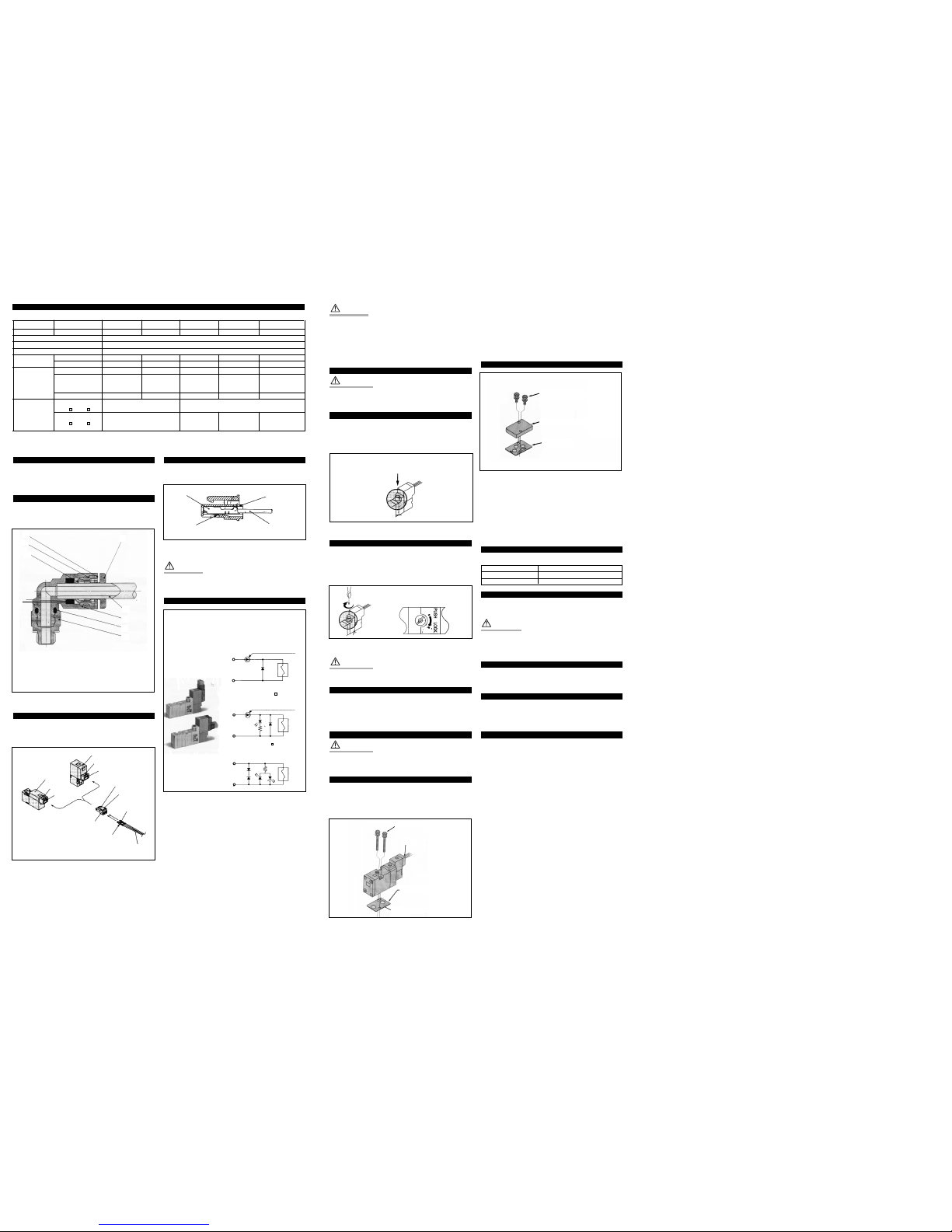
Tube connections - push-in fittings (Fig 4)
1 Ensure the tube 5 is cut square.
2 Push tube 5 into the body 7 until tube stops.
3 Lightly pull tube 5 back to ensure connection.
Tube disconnection (Fig 4)
1 Push collet in 1.
2 While holding collet in 1 withdraw tube 5.
3 Release collet 1.
Connection of plug connector (Fig 5)
1 Push the connector in a straight line onto the pins of the solenoid
ensuring that the lip of the lever is securely positioned in the
groove of the solenoid cover.
Disconnection of plug connector (Fig 6)
1 Press the lever against the connector and pull the connector away
from the solenoid.
CAUTION
Do not exert excessive force on the wires as this may cause contact
failure.
Wiring specifications (Fig 7)
Ensure correct connection of the lead wires to (+) (positive) and
(-) (negative) indications on the connector. For non-polarity type the
lead wires can be connected to either one.
For DC voltages other than 12, 24 incorrect wiring will damage the
surge voltage suppressor circuit. (Incorrect polarity will cause
malfunction).
Solenoids whose lead wires have been pre-wired are red positive and
black negative.
Manifold Specifications
Type For internal pilot Type 20 Type 21 Type 40 Type 41 Type 42
For external pilot - Type 21R - Type 41R Type 42R
Manifold type Single base type /B mount
P(SUP) · R(EXH) type Common SUP · Common EXH
Valve stations 2-20 stations
A port Location Valve Valve Base Base Base
specifications Direction Top Top Bottom Bottom Side
P,R port Rc(PT)
1
/
8
Rc(PT)
1
/
4
Rc(PT)
1
/
8
Rc(PT)
1
/
4
Rc(PT)
1
/
4
Rc(PT)
1
/
8
Port size A port Rc(PT)
1
/
8
Rc(PT)
1
/
8
Rc(PT)
1
/
8
Rc(PT)
1
/
8
C6 (ø6 one-touch fitting)
C8 (ø8 one-touch fitting)
X port
Note 1)
- M3x0.8 - M5x0.8 M5x0.8
Note 2)
Body ported type
10.6 (0.59) -
Valve effective SYJ7 2/SYJ7 2R
area
Base mounted type
- 10.2 (0.57) 10.2 (0.57)
1
/
8
: 9.2 (0.51)
mm
2
(Cv)
SYJ7 4/SYJ7 4R
C6: 8.8 (0.49)
C8: 10 (0.56)
Note 1: Only for external pilot
Note 2:Value when used on a manifold
1
5
7
8
9
6
4
3
2
Fig 4
Fig 7
Fig 6
Fig 10
Fig 11
Fig 8
Fig 9
Fig 5
1 Collet
2 Guide
3 Collar
4 Tube retainer
5 Tube
6 Tube seal
7 Body
8 O-ring
9 Stud
Cover
Cover
Groove
Groove
Pin
Hook
Lead wire
Pin
Lever
DC indicator
Socket
DXT170-71-1
Connector
housing
Socket
Hook
Connector housing
Lead wire
Surge voltage suppressor
(For DC)
Grommet, L and M type plug connector
With surge voltage suppressor
Indicator light and surge
voltage suppressor ( Z)
Non polarity type ( U)
(12V,24VDC only)
Diode to prevent
reverse connection
Diode to prevent
reverse connection
Red (+)
Black (-)
Red (+)
Black (-)
(-) (+)
(+) (-)
Coil
Coil
Coil
Non-locking push type
(Standard type)
Push down in the direction of the arrow.
1
3 Gasket
1
2 Blanking plate
3 Gasket
2
When you enquire about the product, please contact the following
SMC Corporation:
ENGLAND Phone 01908-563888 TURKEY Phone 212-2211512
ITALY Phone 02-92711 GERMANY Phone 6103-402-0
HOLLAND Phone 020-5318888 FRANCE Phone 01-64-76-10-00
SWITZERLAND
Phone 052-34-0022 SWEDEN Phone 08-603 07 00
SPAIN Phone 945-184100 AUSTRIA Phone 02262-62-280
Phone 902-255255 IRELAND Phone 01-4501822
GREECE Phone 01-3426076 DENMARK Phone 8738-0800
FINLAND Phone 09-68 10 21 NORWAY Phone 67-12 90 20
BELGIUM Phone 03-3551464 POLAND Phone 48-22-6131847
 Loading...