

SMC Networks SY3000 SERIES, SY5000 SERIES, SY7000 SERIES Operation Manuals
Doc. No.SY3000V-OMM0002-B
Solenoid Valve
PRODUCT NAME
SY3000/5000/7000 Series
Plug-in Type
MODEL/ Series

Contents
Safety Instructions ---------------------------------------------------------------------------- 2,3
Design / Selection ---------------------------------------------------------------------------- 4,5
Mounting ---------------------------------------------------------------------------------------- 5
Piping -------------------------------------------------------------------------------------------- 6
Wiring -------------------------------------------------------------------------------------------- 6
Lubrication -------------------------------------------------------------------------------------- 7
Air Supply --------------------------------------------------------------------------------------- 7
Operating Environment ---------------------------------------------------------------------- 8
Maintenance ------------------------------------------------------------------------------------ 8
UL approved product ---------------------------------------------------------------------------- 8
Specific Product Precautions --------------------------------------------------------------- 9 ~16
Construction and optional parts ------------------------------------------------------------ 17~19
Trouble shooting ------------------------------------------------------------------------------- 20,21
-1-
S
No.SY3000V-OMM0002-B
Safety Instructions
These safety instructions ar e int ended to prevent hazardous sit uations and/or equipme nt damage.
These instructions indicate the level of potential hazard with the labels of “Caution, ” “Warning” or “Danger . ”
They are all important notes for safety and must be followed in addition to International Standards
(ISO/IEC)*1) , and other safety regulations.
*1) ISO 4414: Pneumatic fluid power -- General rules relating to systems.
ISO 4413: Hydraulic fluid pow er -- General rules relating to systems.
IEC 60204-1: Safety of machinery -- Electrical equipment of machines .(Part 1: General r equir eme nts)
ISO 10218: Manipulating industrial robots -Safety.
etc.
Caution
Caution indicates a hazard with a low level of risk which, if not avoided, could result
in minor or moderate injury.
Warning
Warning
indicates a hazard with a medium level of risk which, if not avoided, could
result in death or serious injury.
Danger
Danger
indicates a hazard with a high level of risk which, if not avoided, will result
in death or serious injury.
Warning
1.
The compatibil ity of the pr oduc t i s the r es pon si bil ity of t he pers on wh o desi gn s the equi pm en t or
decides its specification s.
Since the product specified here is used under various operating conditions, its compatibility with specific
equipment must be dec ided by the person who d esigns the e quipm ent or decide s its spec ifications based o n
necessary analysis and test results.
The expected performance and safety assurance of the equipment will be the responsibility of the person who
has determined its compatibility with the product.
This person should also continuously review all specifications of the product referring to its latest catalog
information, with a view to giving due consideration to any possibility of equipment failure when configuring the
equipment.
2. Only personnel with appropriat e t r aining should operate machine r y and equipment .
The product specified here may become unsafe if handled incorrectly.
The assembly, operation and maintenance of machines or equipment including our products must be
performed by an operator who is appropriately trained and experienced.
3. Do not service or at tempt to remove product and machinery/equi pm ent until safety is confirmed.
1.The inspection and maintenance of machinery/equipment should only be performed after measures to
prevent falling or runaway of the driven objects have been confirmed.
2.When the product is to be removed, confirm that the safety measures as mentioned above are implemented
and the power from any appropriate source is cut, and read and understand the specific product precautions
of all relevant products carefully.
3. Before machinery/equipment is restarted, take measures to prevent unexpected operation and malfunction.
4. Contact SMC beforehand and take special consideration of safety measures if the product is to
be used in any of the following condi t ions.
1. Conditions and environments outside of the given specifications, or use outdoors or in a place exposed to
direct sunlight.
2. Installation on equipment in conjunction with atomic energy, railways, air navigation, space, shipping,
vehicles, military, medical treatment, combustion and recreation, or equipment in contact with food and
beverages, emergency stop circuits, clutch and brake circuits in press applications, safety equipment or
other applications unsuitable for the standard specifications described in the product catalog.
3. An application which could have negative effects on people, property, or animals requiring special safety
analysis.
4.Use in an interlock circuit, which requires the provision of double interlock for possible failure by using a
mechanical protective function, and periodical checks to confirm proper operation.
- 2 -
NoSY3000V-OMM0002-B
Safety Instructions
Caution
1. The product is provided for use in manufacturing industries.
The product herein descr ibed is basically provided f or peaceful use in manufacturing indus trie s.
If considering using the product in other industries, consult SMC
beforehand and exchange
specifications or a contract if necessary.
If anything is unclear, contact your nearest sales branch.
Limited warranty and Disclaimer/Compliance Requirements
The product used is subject to the following “Limited warranty and Disclaimer” and “Compliance
Requirements”.
Read and accept them before using the prod uc t .
Limited warranty and Discla ime r
1.The warranty period of the product is 1 year in service or 1.5 years after the product is
delivered,whichever is first.
∗
2)
Also, the product may have speci f i ed durability, running distance or replacement parts. Pl ease
consult your nearest sales branch.
2. For any failure or da mage reported within the warra nty period which is clearly our r es ponsibility,
a replacement product or necessary parts will be provided.
This limited warr anty applies only to our product independently, and not to any other dama ge
incurred due to the failure of the product.
3. Prior to using SMC products, pl ease read and understa nd the warranty terms and di sclaimers
noted in the specified catalog for the particular products.
∗
2) Vacu um pads are excluded from this 1 year warra nt y.
A vacuum pad is a consumable part , so i t i s warranted for a year after it i s del i vered.
Also, even within the warranty period, the wear of a product due to the use of the vacuum
pad or failure due to the deterioration of rubber material are not covered by the limited
warranty.
Compliance Requireme nt s
1.
The use of SMC products with production equipment for the manufacture of weapons of mass
destruction(WMD) or any other weapon is strictl y prohibited.
2. The exports of SMC products or technology from one country to another are governed by the
relevant
security laws and regulation of the countries involved in the transaction. Prior to the
shipment of a SMC product to another country, assure that all local rules governing that export
are known and f
ollowed.
Caution
SMC products are not intended for use as instruments for legal metrology.
Measurement instruments that SMC manufactures or sells have not been qualified by type approval tests
relevant to the metrology (measurement) laws of each country.
Therefore, SMC products cannot be used for business or certification ordained by the metrology
(measurement) laws of each country.
- 3 -
NoSY3000V-OMM0002-B
Design / Selection
1. Confirm the specification s
Products represented in this instruction manual are
designed only for use in compressed air systems
( including vacuum). Do not operate at pressures
or temperatures, etc., beyond the range of
specifications, as this can cause damage or
malfunction. (Refer to the specifications.) Please
contact SMC when using a fluid other than
compressed air (including vacuum). We do not
guarantee against any damage if the product is
used outside of the specification range.
2. Actuator drive
When an actuator, such as a cylinder, is to be driven
using a valve, take appropriate measures (cover
installation or approach prohibition) to prevent
potential danger caused by actuator operation.
3. Intermediate stops
For 3-position closed center or double check valve
type, it is difficult to make a piston stop at the
required position accurately due to the
compressibility of air.
Furthermore, since valves and cylinders are not
guaranteed for zero air leakage, it may not be
possible to hold a stopped position for an
extended period of time. Please contact SMC if it is
necessary to hold a stopped position for an
extended period of time.
4. Effect of back pressure when using a manifold.
Use caution when valves are used on a manifold,
because an actuator may malfunction due to
back-pressure. For 3-position exhaust center valve
or single acting cylinder, take appropriate measures
to prevent malfunction by using it with an individual
EXH spacer assembly or a back pressure check
valve.
5. Holding pressure (including v acuum).
Since the valve are subject to air leakage, they
cannot be used for applications such as holding
pressure (including vacuum) in a pressure vessel.
6. Not suitable for use as an emergency shut-off
valve, etc.
The valves listed in this instruction manual are not
designed for safety applications such as an
emergency shutoff valve. If the valves are used for
the mentioned applications, additional safety
measures should be adopted.
7. Release of residual pressure
For maintenance purposes install a system for
releasing residual pressure. Especially in the case
of 3-position closed center valve or double c heck
valve type, ensure that the residual pressure
between the valve and the cylinder is released.
8. Operation in a vacuum condition
When a valve is used for switching a vacuum, take
measures to install a suction filter or similar to
prevent external dust or other foreign matter from
entering inside the valve. In addition, at the time of
vacuum adsorption, be sure to supply a constant
supply of vacuum. Failure to do so may result in
foreign matter sticking to the adsorption pad or air
leakage, causing the workpiece to drop.
9. Regarding a vacuum switch valve
For maintenance purposes install a system for
releasing residual pressure.
10. Double solenoid type
When using the double solenoid type for the first
time, actuators may travel in an unexpected
direction depending on the switching position of the
valve. Implement measures to prevent any danger
from occurring when operating the actuator.
11. Ventilation
Provide ventilation when using a valve in a confined
area, such as in a closed control panel. For example,
install a ventilation opening, etc. in order to prevent
pressure from increasing inside of the confined area
and to release the heat generated by the valve.
12. Extended periods of continuous
energization.
If a valve will be continuously energized for
an extended period of time, the temperature
of the valve will increase due to the heat
generated by the coil. This will likely
adversely affect the performance of the
solenoid valve and any nearby peripheral
equipment. Therefore, when it is
continuously energized or the energized
period per day is longer than the
de-energized period use either: DC
specification, power-saving type. Also,
please contact SMC because depending on
the application, there may be additional
valves not mentioned above that may be
used. In addition, it is possible to shorten the
energized time by making a valve with an
N.O. (normally open) specification.
For applications such as mounting a valve on
a control panel, incorporate measure to limit
the heat radiation so that it is within the
operation temperature range.
13. Do not disassemble the product of make
any modifications, including additional
machining.
It may cause human injury and/or an accident.
SY Series
Precautions for 5 Port Solenoid Valve 1
Be sure to read before handling.
Warning
- 4 -
No.SY3000V-OMM0002-B
Design / Selection
1. Momentary energization
If a double solenoid valve is operated with
momentary energization, it should be energized for
at least 0.1 second. However, depending on the
piping conditions, cylinder may malfunction even
when the double solenoid valve is energized for 0.1
second or longer. In this case, energize the double
solenoid valve until the cylinder is exhausted
completely.
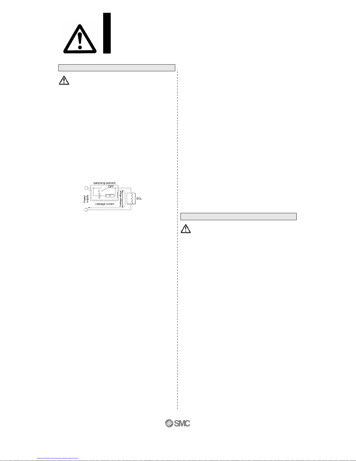
2. Leakage voltage
Take note that the leakage voltage will increase
when a resistor is used in parallel with switching
element or a C-R circuit (surge voltage suppressor)
is used for protecting a switching device because of
the passing leakage voltage through the C-R
circuit. The suppressor residual leakage voltage
should be 3% or less of the rated voltage.
3. Surge voltage suppressor
1) A surge voltage suppressor built into the valve
is intended to protect the output contacts so
that the surge generated inside valve does not
adversely affect the output contacts.
Therefore, if an overvoltage or overcurrent is
received from an external peripheral device,
the surge voltage protection element inside
the valve is overloaded, causing the element
to break. In the worst case, the electri c ci rcuit
enters the short-circuit status by the breakage.
If the energizing continues in this status, a
large current flows. This may cause
secondary damage to the output circuit,
external peripheral device, or valve, and may
also cause fire accident. So, take appropriate
protective measures, such as installation of an
overcurrent protection circuit in the power
supply or drive circuit to maintain the sufficient
safety.
2) If a surge protection circuit contains
nonstandard diodes, such as Zener diodes or
varistor, a residual voltage that is in proportion
to the protective circuit and the rated voltage
will remain. Therefore, take into consideration
the surge voltage protection of the
controller.In the case of diodes, the residual
voltage is approximately 1 V.
4. Operation in a low temperature condition
It is possible to operate a valve in extreme
temperature, as low as -10
o
C. Take appropriate
measures to avoid freezing of drainage, moisture
etc. in low temperature.
5. Operation for air blowing
When using a solenoid valve for air blowing, use an
external pilot type. Use caution because the
pressure drop caused by the air blowing can have
an affect on the internal pilot type valve when the
internal pilot type valves and external pilot type
valves are used on the same manifold. Additionally,
when compressed air within the pressure range of
the established specifications is supplied to the
external pilot type valve’s port, and a double
solenoid valve is used for air blowing, the solenoids
should normally be energized when air is being
blown.
6. Mounting orientation
Rubber seal: Mounting orientation is free.
Metal seal: Mounting orientation of a single solenoid
is universal.
When installing a double solenoid or a 3-position
configuration, mount the valve so that spool valve is
horizontal.
Mounting
1. Operation manual
Install the products and operate them only after
reading the operation manual carefully and
understanding its contents. Also, keep the manual
where it can be referred to as necessary.
2. Ensure sufficient space for maintenance
activities.
When installing the products, allow access for
maintenance.
3. Tighten threads with the proper tightening
torque.
When installing the products, follow the listed torque
specifications.
4. If air leakage increases or equipment does
not operated properly, stop operation.
Check mounting conditions when air and power
supplies are connected. Initial function and leakage
tests should be performed after installation.
5. Painting and coating
Warnings or specifications printed or affixed to the
product should not be erased, removed or covered
up. Please consult with SMC before applying paint
to resinous parts, as this may have an adverse
effect due to the solvent in the paint.
Warning
SY Series
Precautions for 5 Port Solenoid Valve 2
Be sure to read before handling.
Caution
- 5 -
No.SY3000V-OMM0002-B
Piping
1. Refer to the Fittings and Tubing
precautions for handling one-touch
fittings.
2. Preparation before piping
Before piping is connected, it should be thoroughly
blown out with air (flushing) or washed to remove
chips, cutting oil and other debris from inside the
pipe.
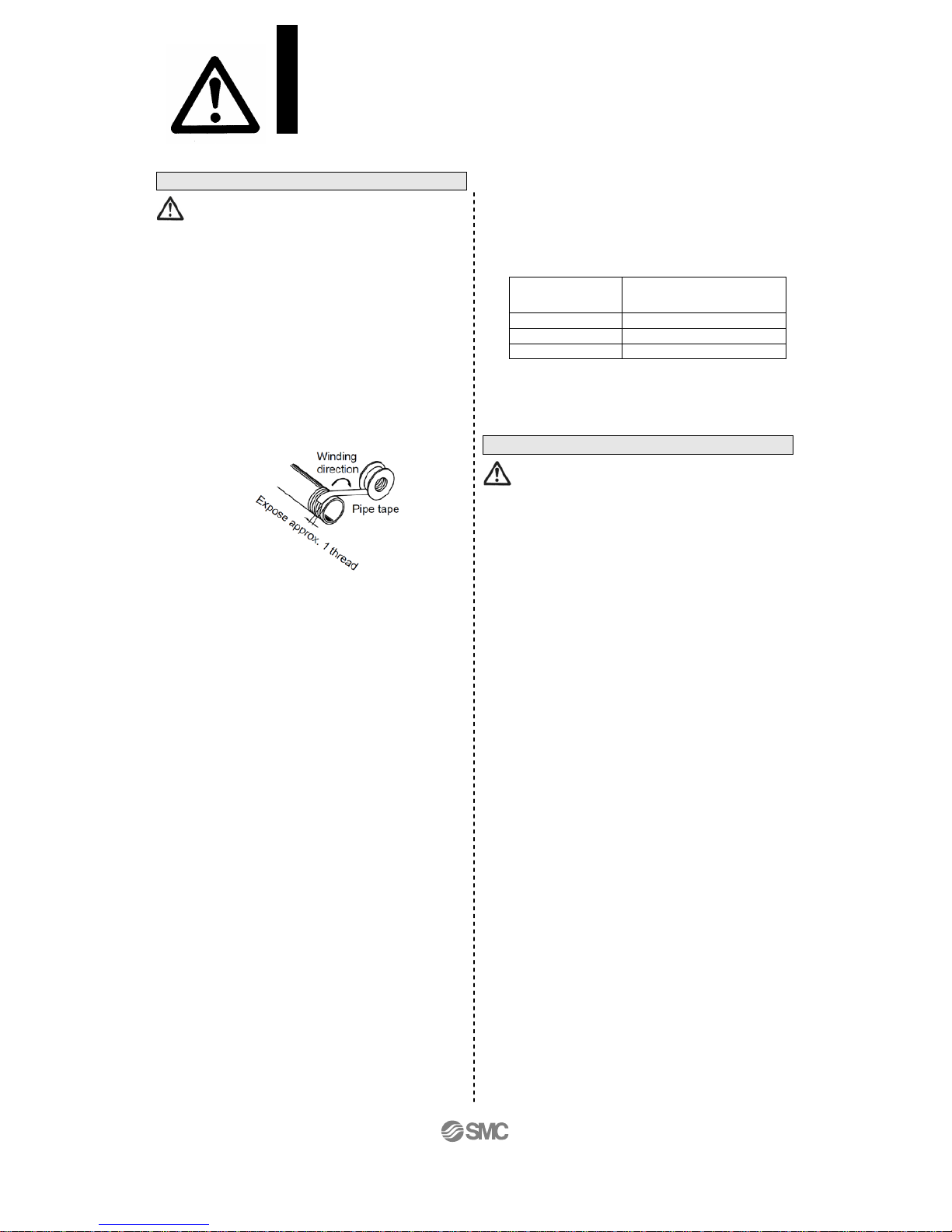
3. Wrapping of pipe tape
When screwing piping or fittings into ports, ensure
that chips from the pipe threads or sealing material
do not enter the piping. Also, if pipe tape is used,
leave 1 thread ridges exposed at the end of the
threads.
4. Closed center and double check valve
types
For the closed center or double check valve types,
check the piping to prevent air leakage from the
piping between the valve and the cylinder.
5. Connection of fittings
When screwing fittings into valves, tighten as
follows.
(1) Follow the procedures below when installing an
SMC fitting, etc.
・ M5 types
After tightening the fitting by hand, use a wrench
to tighten the fitting an additional approximately
1/6 to 1/4 turn. As a reference value, tightening
torque is 1 to 1.5 N・m.
Note) If tightened excessively, the thread of the
product may break or the gasket may deform. If
tightened insufficiently, the thread of the product
may become loose. In either case, air leakage
can occur.
・ Follow the procedure of the manufacture
when fittings other than SMC is used.
(2) Rc type
Tighten with the proper torque shown below.
Tightening Torque for Piping Applicable
Connection
thread
Proper tightening torque
(N
・
m)
Rc1/8
3 to 5
Rc1/4
8 to 12
Rc3/8
14 to 16
6. Piping to products
When piping to a product, avoid mistakes regarding
the supply port, etc.
Wiring
1. Polarity
When connecting power to a solenoid valve with a
DC specification and equipped with a light or surge
voltage suppressor, check for polarity. If there is
polarity, take note of the following.
No diode to protect polarity.
If a mistake is mode regarding the polarity, damage
may occur to the diode in the valve, the switching
element in a control device or power supply
equipment, etc.
With diode to protect polarity.
If polarity connection is wrong, the valve does not
operate.
2. Applied voltage
When electric power is connected to a solenoid
valve, be careful to apply the proper voltage.
Improper voltage may cause malfunction or coil
damage.
3. Check the connections.
Check if the connections are correct after
completing all wiring.
Caution
Caution
SY Series
Precautions for 5 Port Solenoid Valve 3
Be sure to read before handling.
- 6 -
No.SY3000V-OMM0002-B
 Loading...