

Page 1

MANAGEMENT GUIDE
SMC6128PL2
TigerSwitchTM 10/100
24-Port 10/100 Managed Switch with
PoE, IP Clustering and 4 Gigabit Ports
Page 2

Page 3

TigerSwitch 10/100
Management Guide
From SMC’s Tiger line of feature-rich workgroup LAN solutions
20 Mason
Irvine, CA 92618
Phone: (949) 679-8000
Pub. # 149100032800A
March 2008
E032008-EK-R04
Page 4

Information furnished by SMC Networks, Inc. (SMC) is believed to be accurate and
reliable. However, no responsibility is assumed by SMC for its use, nor for any
infringements of patents or other rights of third parties which may result from its use. No
license is granted by implication or otherwise under any patent or patent rights of SMC.
SMC reserves the right to change specifications at any time without notice.
Copyright © 20
08 by
SMC Networks, Inc.
20 Mason
Irvine, CA 92618
All rights reserved. Printed in Taiwan
Trademarks:
SMC is a registered trademark; and EZ Switch, TigerStack, TigerSwitch, and TigerAccess
are trademarks of SMC Networks, Inc. Other product and company names are
trademarks or registered trademarks of their respective holders.
Page 5

Limited Warranty
Limited Warranty Statement: SMC Networks, Inc. (“SMC”) warrants its products to be
free from defects in workmanship and materials, under normal use and service, for the
applicable warranty term. All SMC products carry a standard 90-day limited warranty from
the date of purchase from SMC or its Authorized Reseller. SMC may, at its own discretion,
repair or replace any product not operating as warranted with a similar or functionally
equivalent product, during the applicable warranty term. SMC will endeavor to repair or
replace any product returned under warranty within 30 days of receipt of the product.
The standard limited warranty can be upgraded to a Limited Lifetime* warranty by
registering new products within 30 days of purchase from SMC or its Authorized Reseller.
Registration can be accomplished via the enclosed product registration card or online via
the SMC Web site. Failure to register will not affect the standard limited warranty. The
Limited Lifetime warranty covers a product during the Life of that Product, which is
defined as the period of time during which the product is an “Active” SMC product. A
product is considered to be “Active” while it is listed on the current SMC price list. As new
technologies emerge, older technologies become obsolete and SMC will, at its discretion,
replace an older product in its product line with one that incorporates these newer
technologies. At that point, the obsolete product is discontinued and is no longer an
“Active” SMC product. A list of discontinued products with their respective dates of
discontinuance can be found at:
http://www.smc.com/index.cfm?action=customer_service_warranty.
All products that are replaced become the property of SMC. Replacement products may
be either new or reconditioned. Any replaced or repaired product carries either a 30-day
limited warranty or the remainder of the initial warranty, whichever is longer. SMC is not
responsible for any custom software or firmware, configuration information, or memory
data of Customer contained in, stored on, or integrated with any products returned to
SMC pursuant to any warranty. Products returned to SMC should have any
customer-installed accessory or add-on components, such as expansion modules,
removed prior to returning the product for replacement. SMC is not responsible for these
items if they are returned with the product.
Customers must contact SMC for a Return Material Authorization number prior to
returning any product to SMC. Proof of purchase may be required. Any product returned
to SMC without a valid Return Material Authorization (RMA) number clearly marked on
the outside of the package will be returned to customer at customer’s expense. For
warranty claims within North America, please call our toll-free customer support number
at (800) 762-4968. Customers are responsible for all shipping charges from their facility to
SMC. SMC is responsible for return shipping charges from SMC to customer.
WARRANTIES EXCLUSIVE: IF AN SMC PRODUCT DOES NOT OPERATE AS
WARRANTED ABOVE, CUSTOMER’S SOLE REMEDY SHALL BE REPAIR OR
REPLACEMENT OF THE PRODUCT IN QUESTION, AT SMC’S OPTION. THE
FOREGOING WARRANTIES AND REMEDIES ARE EXCLUSIVE AND ARE IN LIEU OF
ALL OTHER WARRANTIES OR CONDITIONS, EXPRESS OR IMPLIED, EITHER IN
FACT OR BY OPERATION OF LAW, STATUTORY OR OTHERWISE, INCLUDING
WARRANTIES OR CONDITIONS OF MERCHANTABILITY AND FITNESS FOR A
PARTICULAR PURPOSE. SMC NEITHER ASSUMES NOR AUTHORIZES ANY OTHER
PERSON TO ASSUME FOR IT ANY OTHER LIABILITY IN CONNECTION WITH THE
SALE, INSTALLATION, MAINTENANCE OR USE OF ITS PRODUCTS. SMC SHALL
v
Page 6

NOT BE LIABLE UNDER THIS WARRANTY IF ITS TESTING AND EXAMINATION
DISCLOSE THE ALLEGED DEFECT IN THE PRODUCT DOES NOT EXIST OR WAS
CAUSED BY CUSTOMER’S OR ANY THIRD PERSON’S MISUSE, NEGLECT,
IMPROPER INSTALLATION OR TESTING, UNAUTHORIZED ATTEMPTS TO REPAIR,
OR ANY OTHER CAUSE BEYOND THE RANGE OF THE INTENDED USE, OR BY
ACCIDENT, FIRE, LIGHTNING, OR OTHER HAZARD.
LIMITATION OF LIABILITY: IN NO EVENT, WHETHER BASED IN CONTRACT OR
TORT (INCLUDING NEGLIGENCE), SHALL SMC BE LIABLE FOR INCIDENTAL,
CONSEQUENTIAL, INDIRECT, SPECIAL, OR PUNITIVE DAMAGES OF ANY KIND, OR
FOR LOSS OF REVENUE, LOSS OF BUSINESS, OR OTHER FINANCIAL LOSS
ARISING OUT OF OR IN CONNECTION WITH THE SALE, INSTALLATION,
MAINTENANCE, USE, PERFORMANCE, FAILURE, OR INTERRUPTION OF ITS
PRODUCTS, EVEN IF SMC OR ITS AUTHORIZED RESELLER HAS BEEN ADVISED
OF THE POSSIBILITY OF SUCH DAMAGES.
SOME STATES DO NOT ALLOW THE EXCLUSION OF IMPLIED WARRANTIES OR
THE LIMITATION OF INCIDENTAL OR CONSEQUENTIAL DAMAGES FOR
CONSUMER PRODUCTS, SO THE ABOVE LIMITATIONS AND EXCLUSIONS MAY
NOT APPLY TO YOU. THIS WARRANTY GIVES YOU SPECIFIC LEGAL RIGHTS,
WHICH MAY VARY FROM STATE TO STATE. NOTHING IN THIS WARRANTY SHALL
BE TAKEN TO AFFECT YOUR STATUTORY RIGHTS.
* SMC will provide warranty service for one year following discontinuance from the active
SMC price list. Under the limited lifetime warranty, internal and external power supplies,
fans, and cables are covered by a standard one-year warranty from date of purchase.
SMC Networks, Inc.
20 Mason
Irvine, CA 92618
vi
Page 7

About This Guide
Purpose
This guide gives specific information on how to operate and use the management
functions of the switch.
Audience
The guide is intended for use by network administrators who are responsible for operating
and maintaining network equipment; consequently, it assumes a basic working
knowledge of general switch functions, the Internet Protocol (IP), and Simple Network
Management Protocol (SNMP).
Conventions
The following conventions are used throughout this guide to show information:
Note: Emphasizes important information or calls your attention to related features or
instructions.
Caution: Alerts you to a potential hazard that could cause loss of data, or damage the
Warning: Alerts you to a potential hazard that could cause personal injury.
Related Publications
The following publication details the hardware features of the switch, including the
physical and performance-related characteristics, and how to install the switch:
The Installation Guide
Also, as part of the switch’s software, there is an online web-based help that describes all
management related features.
system or equipment.
Revision History
This section summarizes the changes in each revision of this guide.
March 2008 Revision
This is the fourth revision of this guide. This guide is valid for software release v1.1.0.3.
vii
Page 8

viii
Page 9

Contents
Chapter 1: Introduction 1-1
Key Features 1-1
Description of Software Features 1-2
System Defaults 1-6
Chapter 2: Initial Configuration 2-1
Connecting to the Switch 2-1
Configuration Options 2-1
Required Connections 2-2
Remote Connections 2-3
Basic Configuration 2-3
Console Connection 2-3
Setting Passwords 2-4
Setting an IP Address 2-4
Manual Configuration 2-4
Dynamic Configuration 2-5
Enabling SNMP Management Access 2-6
Community Strings (for SNMP version 1 and 2c clients) 2-6
Trap Receivers 2-7
Configuring Access for SNMP Version 3 Clients 2-8
Saving Configuration Settings 2-8
Managing System Files 2-9
Chapter 3: Configuring the Switch 3-1
Using the Web Interface 3-1
Navigating the Web Browser Interface 3-2
Home Page 3-2
Configuration Options 3-3
Panel Display 3-3
Main Menu 3-4
Basic Configuration 3-12
Displaying System Information 3-12
Displaying Switch Hardware/Software Versions 3-13
Displaying Bridge Extension Capabilities 3-15
Setting the Switch’s IP Address 3-16
Manual Configuration 3-17
Using DHCP/BOOTP 3-18
Enabling Jumbo Frames 3-19
Managing Firmware 3-19
Downloading System Software from a Server 3-20
i
Page 10

Contents
Saving or Restoring Configuration Settings 3-21
Downloading Configuration Settings from a Server 3-22
Console Port Settings 3-23
Telnet Settings 3-25
Configuring Event Logging 3-28
Displaying Log Messages 3-28
System Log Configuration 3-28
Remote Log Configuration 3-30
Simple Mail Transfer Protocol 3-32
Resetting the System 3-34
Setting the System Clock 3-35
Setting the Time Manually 3-35
Configuring SNTP 3-35
Configuring NTP 3-36
Setting the Time Zone 3-38
Simple Network Management Protocol 3-39
Setting Community Access Strings 3-40
Specifying Trap Managers and Trap Types 3-41
Enabling SNMP Agent Status 3-42
Configuring SNMPv3 Management Access 3-43
Setting the Local Engine ID 3-43
Specifying a Remote Engine ID 3-44
Configuring SNMPv3 Users 3-44
Configuring Remote SNMPv3 Users 3-46
Configuring SNMPv3 Groups 3-47
Setting SNMPv3 Views 3-50
User Authentication 3-52
Configuring User Accounts 3-52
Configuring Local/Remote Logon Authentication 3-54
Configuring Encryption Keys 3-58
AAA Authorization and Accounting 3-60
Configuring AAA RADIUS Group Settings 3-61
Configuring AAA TACACS+ Group Settings 3-61
Configuring AAA Accounting 3-62
AAA Accounting Update 3-64
AAA Accounting 802.1X Port Settings 3-65
AAA Accounting Exec Command Privileges 3-66
AAA Accounting Exec Settings 3-67
AAA Accounting Summary 3-67
Authorization Settings 3-69
Authorization EXEC Settings 3-70
Authorization Summary 3-70
Configuring HTTPS 3-71
Replacing the Default Secure-site Certificate 3-72
Configuring the Secure Shell 3-74
ii
Page 11

Contents
Configuring the SSH Server 3-76
Generating the Host Key Pair 3-77
Importing User Public Keys 3-79
Configuring Port Security 3-82
Configuring 802.1X Port Authentication 3-83
Displaying 802.1X Global Settings 3-85
Configuring 802.1X Global Settings 3-86
Configuring Port Settings for 802.1X 3-86
Displaying 802.1X Statistics 3-89
Web Authentication 3-90
Configuring Web Authentication 3-91
Configuring Web Authentication for Ports 3-92
Displaying Web Authentication Port Information 3-93
Re-authenticating Web Authenticated Ports 3-94
Network Access – MAC Address Authentication 3-95
Configuring the MAC Authentication Reauthentication Time 3-96
Configuring MAC Authentication for Ports 3-97
Configuring Port Link Detection 3-98
Displaying Secure MAC Address Information 3-99
MAC Authentication 3-101
Configuring MAC authentication parameters for ports 3-101
Access Control Lists 3-102
Configuring Access Control Lists 3-102
Setting the ACL Name and Type 3-102
Configuring a Standard IP ACL 3-103
Configuring an Extended IP ACL 3-104
Configuring a MAC ACL 3-107
Binding a Port to an Access Control List 3-109
Filtering IP Addresses for Management Access 3-110
Port Configuration 3-112
Displaying Connection Status 3-112
Configuring Interface Connections 3-114
Creating Trunk Groups 3-116
Statically Configuring a Trunk 3-117
Enabling LACP on Selected Ports 3-118
Configuring LACP Parameters 3-120
Displaying LACP Port Counters 3-122
Displaying LACP Settings and Status for the Local Side 3-124
Displaying LACP Settings and Status for the Remote Side 3-126
Setting Broadcast Storm Thresholds 3-127
Configuring Port Mirroring 3-129
Configuring Rate Limits 3-130
Rate Limit Configuration 3-130
Showing Port Statistics 3-131
Power Over Ethernet Settings 3-135
iii
Page 12

Contents
Switch Power Status 3-136
Setting a Switch Power Budget 3-137
Displaying Port Power Status 3-137
Configuring Port PoE Power 3-138
Address Table Settings 3-140
Setting Static Addresses 3-140
Displaying the Address Table 3-141
Changing the Aging Time 3-142
Spanning Tree Algorithm Configuration 3-143
Configuring Port and Trunk Loopback Detection 3-145
Displaying Global Settings 3-146
Configuring Global Settings 3-148
Displaying Interface Settings 3-152
Configuring Interface Settings 3-155
Configuring Multiple Spanning Trees 3-157
Displaying Interface Settings for MSTP 3-160
Configuring Interface Settings for MSTP 3-162
VLAN Configuration 3-163
IEEE 802.1Q VLANs 3-163
Enabling or Disabling GVRP (Global Setting) 3-166
Displaying Basic VLAN Information 3-167
Displaying Current VLANs 3-168
Creating VLANs 3-169
Adding Static Members to VLANs (VLAN Index) 3-170
Adding Static Members to VLANs (Port Index) 3-172
Configuring VLAN Behavior for Interfaces 3-173
Configuring IEEE 802.1Q Tunneling 3-175
Enabling QinQ Tunneling on the Switch 3-178
Adding an Interface to a QinQ Tunnel 3-180
Private VLANs 3-181
Displaying Current Private VLANs 3-182
Configuring Private VLANs 3-183
Associating VLANs 3-184
Displaying Private VLAN Interface Information 3-184
Configuring Private VLAN Interfaces 3-185
Protocol VLANs 3-187
Protocol VLAN Group Configuration 3-187
Protocol VLAN System Configuration 3-188
Link Layer Discovery Protocol 3-189
Setting LLDP Timing Attributes 3-189
Configuring LLDP Interface Attributes 3-191
Displaying LLDP Local Device Information 3-194
Displaying LLDP Remote Port Information 3-195
Displaying LLDP Remote Information Details 3-196
Displaying Device Statistics 3-197
iv
Page 13

Contents
Displaying Detailed Device Statistics 3-198
Class of Service Configuration 3-199
Layer 2 Queue Settings 3-199
Setting the Default Priority for Interfaces 3-199
Mapping CoS Values to Egress Queues 3-201
Enabling CoS 3-202
Selecting the Queue Mode 3-203
Setting the Service Weight for Traffic Classes 3-203
Layer 3/4 Priority Settings 3-204
Mapping Layer 3/4 Priorities to CoS Values 3-204
Enabling IP DSCP Priority 3-205
Mapping DSCP Priority 3-206
Quality of Service 3-207
Configuring Quality of Service Parameters 3-208
Configuring a Class Map 3-208
Creating QoS Policies 3-211
Attaching a Policy Map to Ingress Queues 3-214
VoIP Traffic Configuration 3-215
Configuring VoIP Traffic 3-215
Configuring VoIP Traffic Port 3-216
Configuring Telephony OUI 3-219
Multicast Filtering 3-220
Layer 2 IGMP (Snooping and Query) 3-220
Configuring IGMP Snooping and Query Parameters 3-221
Enabling IGMP Immediate Leave 3-223
Displaying Interfaces Attached to a Multicast Router 3-225
Specifying Static Interfaces for a Multicast Router 3-226
Displaying Port Members of Multicast Services 3-227
Assigning Ports to Multicast Services 3-228
IGMP Filtering and Throttling 3-229
Enabling IGMP Filtering and Throttling 3-229
Configuring IGMP Filter Profiles 3-230
Configuring IGMP Filtering and Throttling for Interfaces 3-232
Multicast VLAN Registration 3-234
Configuring Global MVR Settings 3-235
Displaying MVR Interface Status 3-236
Displaying Port Members of Multicast Groups 3-237
Configuring MVR Interface Status 3-238
Assigning Static Multicast Groups to Interfaces 3-239
DHCP Snooping 3-240
DHCP Snooping Configuration 3-241
DHCP Snooping VLAN Configuration 3-242
DHCP Snooping Information Option Configuration 3-243
DHCP Snooping Port Configuration 3-244
DHCP Snooping Binding Information 3-245
v
Page 14

Contents
IP Source Guard 3-246
IP Source Guard Port Configuration 3-246
Static IP Source Guard Binding Configuration 3-247
Dynamic IP Source Guard Binding Information 3-249
Switch Clustering 3-250
Cluster Configuration 3-250
Cluster Member Configuration 3-251
Cluster Member Information 3-252
Cluster Candidate Information 3-253
UPnP 3-254
UPnP Configuration 3-254
Chapter 4: Command Line Interface 4-1
Using the Command Line Interface 4-1
Accessing the CLI 4-1
Console Connection 4-1
Telnet Connection 4-2
Entering Commands 4-3
Keywords and Arguments 4-3
Minimum Abbreviation 4-3
Command Completion 4-3
Getting Help on Commands 4-3
Showing Commands 4-4
Partial Keyword Lookup 4-5
Negating the Effect of Commands 4-5
Using Command History 4-5
Understanding Command Modes 4-5
Exec Commands 4-6
Configuration Commands 4-7
Command Line Processing 4-8
Command Groups 4-9
Line Commands 4-10
line 4-11
login 4-11
password 4-12
timeout login response 4-13
exec-timeout 4-14
password-thresh 4-14
silent-time 4-15
databits 4-16
parity 4-16
speed 4-17
stopbits 4-17
disconnect 4-18
vi
Page 15

Contents
show line 4-18
General Commands 4-19
enable 4-20
disable 4-20
configure 4-21
show history 4-21
reload 4-22
reload cancel 4-23
show reload 4-23
end 4-24
exit 4-24
quit 4-25
System Management Commands 4-25
Device Designation Commands 4-26
prompt 4-26
hostname 4-26
Banner 4-27
banner configure 4-28
banner configure company 4-29
banner configure dc-power-info 4-30
banner configure department 4-31
banner configure equipment-info 4-31
banner configure equipment-location 4-32
banner configure ip-lan 4-33
banner configure lp-number 4-33
banner configure manager-info 4-34
banner configure mux 4-35
banner configure note 4-35
show banner 4-36
User Access Commands 4-37
username 4-37
enable password 4-38
IP Filter Commands 4-39
management 4-39
show management 4-40
Web Server Commands 4-41
ip http port 4-41
ip http server 4-41
ip http secure-server 4-42
ip http secure-port 4-43
Telnet Server Commands 4-44
ip telnet port 4-44
ip telnet server 4-44
Secure Shell Commands 4-45
ip ssh server 4-47
vii
Page 16

Contents
ip ssh timeout 4-48
ip ssh authentication-retries 4-48
ip ssh server-key size 4-49
delete public-key 4-49
ip ssh crypto host-key generate 4-50
ip ssh crypto zeroize 4-50
ip ssh save host-key 4-51
show ip ssh 4-51
show ssh 4-52
show public-key 4-53
Event Logging Commands 4-54
logging on 4-54
logging history 4-55
logging host 4-56
logging facility 4-56
logging trap 4-57
clear logging 4-57
show logging 4-58
show log 4-59
SMTP Alert Commands 4-60
logging sendmail host 4-60
logging sendmail level 4-61
logging sendmail source-email 4-62
logging sendmail destination-email 4-62
logging sendmail 4-63
show logging sendmail 4-63
Time Commands 4-64
sntp client 4-64
sntp server 4-65
sntp poll 4-66
show sntp 4-66
ntp client 4-67
ntp server 4-68
ntp poll 4-69
ntp authenticate 4-69
ntp authentication-key 4-70
show ntp 4-71
clock timezone-predefined 4-71
clock timezone 4-72
clock summer-time (date) 4-73
clock summer-time (predefined) 4-74
clock summer-time (recurring) 4-75
calendar set 4-76
show calendar 4-76
System Status Commands 4-77
viii
Page 17

Contents
show startup-config 4-77
show running-config 4-79
show system 4-81
show users 4-81
show version 4-82
Frame Size Commands 4-83
jumbo frame 4-83
Flash/File Commands 4-84
copy 4-84
delete 4-87
dir 4-88
whichboot 4-89
boot system 4-89
Authentication Commands 4-90
Authentication Sequence 4-90
authentication login 4-91
authentication enable 4-92
RADIUS Client 4-93
radius-server host 4-94
radius-server acct-port 4-94
radius-server auth-port 4-95
radius-server key 4-95
radius-server retransmit 4-96
radius-server timeout 4-96
show radius-server 4-96
TACACS+ Client 4-97
tacacs-server host 4-98
tacacs-server port 4-98
tacacs-server key 4-99
tacacs-server retransmit 4-99
tacacs-server timeout 4-100
show tacacs-server 4-100
AAA Commands 4-101
aaa group server 4-101
server 4-102
aaa accounting dot1x 4-102
aaa accounting exec 4-103
aaa accounting commands 4-104
aaa accounting update 4-105
accounting dot1x 4-106
accounting exec 4-106
accounting commands 4-107
aaa authorization exec 4-107
authorization exec 4-108
show accounting 4-109
ix
Page 18

Contents
Port Security Commands 4-110
port security 4-110
802.1X Port Authentication 4-112
dot1x system-auth-control 4-112
dot1x default 4-113
dot1x max-req 4-113
dot1x port-control 4-113
dot1x operation-mode 4-114
dot1x re-authenticate 4-115
dot1x re-authentication 4-115
dot1x timeout quiet-period 4-115
dot1x timeout re-authperiod 4-116
dot1x timeout tx-period 4-116
dot1x intrusion-action 4-117
show dot1x 4-117
Network Access – MAC Address Authentication 4-121
network-access mode 4-122
network-access max-mac-count 4-123
mac-authentication intrusion-action 4-123
mac-authentication max-mac-count 4-124
network-access dynamic-qos 4-124
network-access dynamic-vlan 4-125
network-access guest-vlan 4-125
network-access link-detection 4-126
network-access link-detection link-down 4-126
network-access link-detection link-up 4-127
network-access link-detection link-up-down 4-127
mac-authentication reauth-time 4-128
clear network-access 4-129
show network-access 4-129
show network-access mac-address-table 4-130
Web Authentication 4-131
web-auth login-attempts 4-132
web-auth login-fail-page-url 4-132
web-auth login-page-url 4-133
web-auth login-success-page-url 4-133
web-auth quiet-period 4-134
web-auth session-timeout 4-134
web-auth system-auth-control 4-135
web-auth 4-135
show web-auth 4-136
show web-auth interface 4-136
web-auth re-authenticate (Port) 4-137
web-auth re-authenticate (IP) 4-137
show web-auth summary 4-138
x
Page 19

Contents
Access Control List Commands 4-139
IP ACLs 4-140
access-list ip 4-140
permit, deny (Standard ACL) 4-141
permit, deny (Extended ACL) 4-142
show ip access-list 4-143
ip access-group 4-144
show ip access-group 4-144
MAC ACLs 4-145
access-list mac 4-145
permit, deny (MAC ACL) 4-146
show mac access-list 4-147
mac access-group 4-148
show mac access-group 4-148
ACL Information 4-149
show access-list 4-149
show access-group 4-149
SNMP Commands 4-150
snmp-server 4-150
show snmp 4-151
snmp-server community 4-152
snmp-server contact 4-152
snmp-server location 4-153
snmp-server host 4-153
snmp-server enable traps 4-155
snmp-server engine-id 4-156
show snmp engine-id 4-157
snmp-server view 4-158
show snmp view 4-159
snmp-server group 4-159
show snmp group 4-161
snmp-server user 4-162
show snmp user 4-163
Interface Commands 4-166
interface 4-166
description 4-167
speed-duplex 4-167
negotiation 4-168
capabilities 4-169
flowcontrol 4-170
shutdown 4-171
switchport packet-rate 4-172
clear counters 4-172
show interfaces status 4-173
show interfaces counters 4-174
xi
Page 20

Contents
show interfaces switchport 4-175
Mirror Port Commands 4-177
port monitor 4-177
show port monitor 4-178
Rate Limit Commands 4-179
rate-limit 4-179
Link Aggregation Commands 4-180
channel-group 4-181
lacp 4-181
lacp system-priority 4-183
lacp admin-key (Ethernet Interface) 4-183
lacp admin-key (Port Channel) 4-184
lacp port-priority 4-185
show lacp 4-186
Power over Ethernet Commands 4-190
power mainpower maximum allocation 4-190
power inline compatible 4-191
power inline 4-192
power inline maximum allocation 4-192
power inline priority 4-193
show power inline status 4-194
show power mainpower 4-195
Address Table Commands 4-195
mac-address-table static 4-196
clear mac-address-table dynamic 4-197
show mac-address-table 4-197
mac-address-table aging-time 4-198
show mac-address-table aging-time 4-198
Spanning Tree Commands 4-199
spanning-tree 4-200
spanning-tree mode 4-200
spanning-tree forward-time 4-202
spanning-tree hello-time 4-202
spanning-tree max-age 4-203
spanning-tree priority 4-204
spanning-tree pathcost method 4-204
spanning-tree transmission-limit 4-205
spanning-tree mst-configuration 4-205
mst vlan 4-206
mst priority 4-207
name 4-207
revision 4-208
max-hops 4-208
spanning-tree spanning-disabled 4-209
spanning-tree cost 4-209
xii
Page 21

Contents
spanning-tree port-priority 4-210
spanning-tree edge-port 4-211
spanning-tree portfast 4-212
spanning-tree link-type 4-212
spanning-tree loopback-detection 4-213
spanning-tree loopback-detection release-mode 4-214
spanning-tree loopback-detection trap 4-214
spanning-tree mst cost 4-215
spanning-tree mst port-priority 4-216
spanning-tree protocol-migration 4-217
show spanning-tree 4-217
show spanning-tree mst configuration 4-219
VLAN Commands 4-219
GVRP and Bridge Extension Commands 4-220
bridge-ext gvrp 4-220
show bridge-ext 4-221
switchport gvrp 4-221
show gvrp configuration 4-222
garp timer 4-222
show garp timer 4-223
Editing VLAN Groups 4-224
vlan database 4-224
vlan 4-225
Configuring VLAN Interfaces 4-226
interface vlan 4-226
switchport mode 4-227
switchport acceptable-frame-types 4-227
switchport ingress-filtering 4-228
switchport native vlan 4-229
switchport allowed vlan 4-230
switchport forbidden vlan 4-231
Displaying VLAN Information 4-232
show vlan 4-232
Configuring IEEE 802.1Q Tunneling 4-233
dot1q-tunnel system-tunnel-control 4-234
switchport dot1q-tunnel mode 4-234
switchport dot1q-tunnel tpid 4-235
show dot1q-tunnel 4-236
Configuring Private VLANs 4-236
private-vlan 4-238
private vlan association 4-239
switchport mode private-vlan 4-239
switchport private-vlan host-association 4-240
switchport private-vlan isolated 4-241
switchport private-vlan mapping 4-241
xiii
Page 22

Contents
show vlan private-vlan 4-242
Configuring Protocol-based VLANs 4-243
protocol-vlan protocol-group (Configuring Groups) 4-244
protocol-vlan protocol-group (Configuring VLANs) 4-244
show protocol-vlan protocol-group 4-245
show protocol-vlan protocol-group-vid 4-246
LLDP Commands 4-246
lldp 4-248
lldp holdtime-multiplier 4-248
lldp medFastStartCount 4-249
lldp notification-interval 4-249
lldp refresh-interval 4-250
lldp reinit-delay 4-251
lldp tx-delay 4-251
lldp admin-status 4-252
lldp notification 4-252
lldp mednotification 4-253
lldp basic-tlv management-ip-address 4-254
lldp basic-tlv port-description 4-255
lldp basic-tlv system-capabilities 4-255
lldp basic-tlv system-description 4-256
lldp basic-tlv system-name 4-256
lldp dot1-tlv proto-ident 4-257
lldp dot1-tlv proto-vid 4-257
lldp dot1-tlv pvid 4-258
lldp dot1-tlv vlan-name 4-258
lldp dot3-tlv link-agg 4-259
lldp dot3-tlv mac-phy 4-259
lldp dot3-tlv max-frame 4-260
lldp dot3-tlv poe 4-260
lldp medtlv extpoe 4-261
lldp medtlv inventory 4-261
lldp medtlv location 4-262
lldp medtlv med-cap 4-262
lldp medtlv network-policy 4-263
show lldp config 4-263
show lldp info local-device 4-265
show lldp info remote-device 4-266
show lldp info statistics 4-267
Priority Commands 4-268
Priority Commands (Layer 2) 4-268
queue mode 4-268
switchport priority default 4-269
queue bandwidth 4-270
queue cos-map 4-271
xiv
Page 23

Contents
show queue mode 4-272
show queue bandwidth 4-272
show queue cos-map 4-272
Priority Commands (Layer 3 and 4) 4-273
map ip dscp (Global Configuration) 4-273
map ip dscp (Interface Configuration) 4-274
show map ip dscp 4-275
Quality of Service Commands 4-276
class-map 4-277
match 4-278
policy-map 4-279
class 4-279
set 4-280
police 4-281
service-policy 4-282
show class-map 4-283
show policy-map 4-283
show policy-map interface 4-284
Voice VLAN Commands 4-284
voice vlan 4-285
voice vlan aging 4-286
voice vlan mac-address 4-286
switchport voice vlan 4-287
switchport voice vlan rule 4-288
switchport voice vlan security 4-288
switchport voice vlan priority 4-289
show voice vlan 4-290
Multicast Filtering Commands 4-291
IGMP Snooping Commands 4-291
ip igmp snooping 4-292
ip igmp snooping vlan static 4-292
ip igmp snooping version 4-293
ip igmp snooping leave-proxy 4-293
ip igmp snooping immediate-leave 4-294
show ip igmp snooping 4-295
show mac-address-table multicast 4-295
IGMP Query Commands (Layer 2) 4-296
ip igmp snooping querier 4-296
ip igmp snooping query-count 4-297
ip igmp snooping query-interval 4-297
ip igmp snooping query-max-response-time 4-298
ip igmp snooping router-port-expire-time 4-299
Static Multicast Routing Commands 4-299
ip igmp snooping vlan mrouter 4-300
show ip igmp snooping mrouter 4-300
xv
Page 24

Contents
IGMP Filtering and Throttling Commands 4-301
ip igmp filter (Global Configuration) 4-302
ip igmp profile 4-302
permit, deny 4-303
range 4-303
ip igmp filter (Interface Configuration) 4-304
ip igmp max-groups 4-305
ip igmp max-groups action 4-305
show ip igmp filter 4-306
show ip igmp profile 4-307
show ip igmp throttle interface 4-307
Multicast VLAN Registration Commands 4-308
mvr (Global Configuration) 4-308
mvr (Interface Configuration) 4-309
show mvr 4-311
IP Interface Commands 4-313
ip address 4-314
ip default-gateway 4-315
ip dhcp restart 4-315
show ip interface 4-316
show ip redirects 4-316
ping 4-317
IP Source Guard Commands 4-318
ip source-guard 4-318
ip source-guard binding 4-320
show ip source-guard 4-321
show ip source-guard binding 4-321
DHCP Snooping Commands 4-322
ip dhcp snooping 4-322
ip dhcp snooping vlan 4-324
ip dhcp snooping trust 4-325
ip dhcp snooping verify mac-address 4-325
ip dhcp snooping information option 4-326
ip dhcp snooping information policy 4-327
ip dhcp snooping database flash 4-327
show ip dhcp snooping 4-328
show ip dhcp snooping binding 4-328
Switch Cluster Commands 4-328
cluster 4-329
cluster commander 4-329
cluster ip-pool 4-330
cluster member 4-331
rcommand 4-331
show cluster 4-332
show cluster members 4-332
xvi
Page 25

Contents
show cluster candidates 4-332
UPnP Commands 4-333
upnp device 4-333
upnp device ttl 4-334
upnp device advertise duration 4-334
show upnp 4-335
Appendix A: Software Specifications A-1
Software Features A-1
Management Features A-2
Standards A-2
Management Information Bases A-3
Appendix B: Troubleshooting B-1
Problems Accessing the Management Interface B-1
Using System Logs B-2
Glossary
Index
xvii
Page 26

Contents
xviii
Page 27

Tables
Table 1-1 Key Features 1-1
Table 1-2 System Defaults 1-6
Table 3-1 Configuration Options 3-3
Table 3-2 Main Menu 3-4
Table 3-3 Logging Levels 3-29
Table 3-5 Supported Notification Messages 3-47
Table 3-6 HTTPS System Support 3-71
Table 3-7 802.1X Statistics 3-89
Table 3-8 LACP Port Counters 3-122
Table 3-9 LACP Internal Configuration Information 3-124
Table 3-10 LACP Neighbor Configuration Information 3-126
Table 3-11 Port Statistics 3-131
Table 3-12 Mapping CoS Values to Egress Queues 3-201
Table 3-13 CoS Priority Levels 3-201
Table 3-14 Mapping DSCP Priority Values 3-206
Table 4-1 Command Modes 4-6
Table 4-2 Configuration Modes 4-7
Table 4-3 Command Line Processing 4-8
Table 4-4 Command Groups 4-9
Table 4-5 Line Commands 4-10
Table 4-6 General Commands 4-19
Table 4-7 System Management Commands 4-25
Table 4-8 Device Designation Commands 4-26
Table 4-9 Banner Commands 4-27
Table 4-10 User Access Commands 4-37
Table 4-11 Default Login Settings 4-37
Table 4-12 IP Filter Commands 4-39
Table 4-13 Web Server Commands 4-41
Table 4-14 HTTPS System Support 4-42
Table 4-15 Telnet Server Commands 4-44
Table 4-16 SSH Commands 4-45
Table 4-17 show ssh - display description 4-52
Table 4-18 Event Logging Commands 4-54
Table 4-19 Logging Levels 4-55
Table 4-20 show logging flash/ram - display description 4-58
Table 4-21 show logging trap - display description 4-59
Table 4-22 SMTP Alert Commands 4-60
Table 4-23 Time Commands 4-64
Table 4-24 Predefined Summer-Time Parameters 4-74
Table 4-25 System Status Commands 4-77
Table 4-26 Frame Size Commands 4-83
Table 4-27 Flash/File Commands 4-84
xix
Page 28

Tables
Table 4-28 File Directory Information 4-88
Table 4-29 Authentication Commands 4-90
Table 4-30 Authentication Sequence 4-90
Table 4-31 RADIUS Client Commands 4-93
Table 4-32 TACACS Commands 4-97
Table 4-34 Port Security Commands 4-110
Table 4-35 802.1X Port Authentication 4-112
Table 4-36 Network Access 4-121
Table 4-37 Web Authentication 4-131
Table 4-38 Access Control Lists 4-139
Table 4-39 IP ACLs 4-140
Table 4-40 MAC ACL Commands 4-145
Table 4-41 ACL Information 4-149
Table 4-42 SNMP Commands 4-150
Table 4-43 show snmp engine-id - display description 4-157
Table 4-44 show snmp view - display description 4-159
Table 4-45 show snmp group - display description 4-162
Table 4-46 show snmp user - display description 4-164
Table 4-47 Interface Commands 4-166
Table 4-48 Interfaces Switchport Statistics 4-176
Table 4-49 Mirror Port Commands 4-177
Table 4-50 Rate Limit Commands 4-179
Table 4-51 Link Aggregation Commands 4-180
Table 4-52 show lacp counters - display description 4-187
Table 4-53 show lacp internal - display description 4-187
Table 4-54 show lacp neighbors - display description 4-189
Table 4-55 show lacp sysid - display description 4-189
Table 4-59 Address Table Commands 4-195
Table 4-60 Spanning Tree Commands 4-199
Table 4-61 VLANs 4-219
Table 4-62 GVRP and Bridge Extension Commands 4-220
Table 4-63 Editing VLAN Groups 4-224
Table 4-64 Configuring VLAN Interfaces 4-226
Table 4-65 Show VLAN Commands 4-232
Table 4-66 IEEE 802.1Q Tunneling Commands 4-233
Table 4-67 Private VLAN Commands 4-237
Table 4-68 Protocol-based VLAN Commands 4-243
Table 4-69 LLDP Commands 4-246
Table 4-70 Priority Commands 4-268
Table 4-71 Priority Commands (Layer 2) 4-268
Table 4-72 Default CoS Values to Egress Queues 4-271
Table 4-73 Priority Commands (Layer 3 and 4) 4-273
Table 4-74 IP DSCP to CoS Vales 4-274
Table 4-75 Quality of Service Commands 4-276
Table 4-76 Voice VLAN Commands 4-284
xx
Page 29

Tables
Table 4-77 Multicast Filtering Commands 4-291
Table 4-78 IGMP Snooping Commands 4-291
Table 4-79 IGMP Query Commands (Layer 2) 4-296
Table 4-80 Static Multicast Routing Commands 4-299
Table 4-81 IGMP Filtering and Throttling Commands 4-301
Table 4-82 Multicast VLAN Registration Commands 4-308
Table 4-83 show mvr - display description 4-312
Table 4-84 show mvr interface - display description 4-312
Table 4-85 show mvr members - display description 4-313
Table 4-86 IP Interface Commands 4-313
Table 4-87 IP Source Guard Commands 4-318
Table 4-88 DHCP Snooping Commands 4-322
Table 4-89 Switch Cluster Commands 4-328
Table B-1 Troubleshooting Chart B-1
xxi
Page 30

Tables
xxii
Page 31

Figures
Figure 3-1 Home Page 3-2
Figure 3-2 Panel Display 3-3
Figure 3-3 System Information 3-12
Figure 3-4 Switch Information 3-14
Figure 3-5 Bridge Extension Configuration 3-15
Figure 3-6 Manual IP Configuration 3-17
Figure 3-7 DHCP IP Configuration 3-18
Figure 3-8 Jumbo Frames Configuration 3-19
Figure 3-9 Copy Firmware 3-20
Figure 3-10 Deleting Files 3-21
Figure 3-11 Downloading Configuration Settings for Startup 3-22
Figure 3-12 Setting the Startup Configuration Settings 3-23
Figure 3-13 Console Port Settings 3-24
Figure 3-14 Enabling Telnet 3-26
Figure 3-15 Displaying Logs 3-28
Figure 3-16 System Logs 3-29
Figure 3-17 Remote Logs 3-31
Figure 3-18 Enabling and Configuring SMTP 3-33
Figure 3-19 Resetting the System 3-34
Figure 3-20 SNTP Configuration 3-36
Figure 3-21 NTP Client Configuration 3-37
Figure 3-22 Setting the System Clock 3-38
Figure 3-23 Configuring SNMP Community Strings 3-41
Figure 3-24 Configuring IP Trap Managers 3-42
Figure 3-25 Enabling SNMP Agent Status 3-42
Figure 3-26 Setting an Engine ID 3-43
Figure 3-27 Setting a Remote Engine ID 3-44
Figure 3-28 Configuring SNMPv3 Users 3-45
Figure 3-29 Configuring Remote SNMPv3 Users 3-46
Figure 3-30 Configuring SNMPv3 Groups 3-49
Figure 3-31 Configuring SNMPv3 Views 3-51
Figure 3-32 Access Levels 3-53
Figure 3-33 Authentication Settings 3-56
Figure 3-34 Encryption Key Settings 3-58
Figure 3-35 AAA Radius Group Settings 3-61
Figure 3-36 AAA TACACS+ Group Settings 3-62
Figure 3-37 AAA Accounting Settings 3-63
Figure 3-38 AAA Accounting Update 3-64
Figure 3-39 AAA Accounting 802.1X Port Settings 3-65
Figure 3-40 AAA Accounting Exec Command Privileges 3-66
Figure 3-41 AAA Accounting Exec Settings 3-67
Figure 3-42 AAA Accounting Summary 3-68
xxiii
Page 32

Figures
Figure 3-43 AAA Authorization Settings 3-69
Figure 3-44 AAA Authorization Exec Settings 3-70
Figure 3-45 AAA Authorization Summary 3-71
Figure 3-46 HTTPS Settings 3-72
Figure 3-47 HTTPS Settings 3-73
Figure 3-48 SSH Server Settings 3-77
Figure 3-49 SSH Host-Key Settings 3-78
Figure 3-50 SSH User Public-Key Settings 3-80
Figure 3-51 Configuring Port Security 3-83
Figure 3-52 802.1X Global Information 3-85
Figure 3-53 802.1X Global Configuration 3-86
Figure 3-54 802.1X Port Configuration 3-87
Figure 3-55 Displaying 802.1X Port Statistics 3-90
Figure 3-56 Web Authentication Configuration 3-91
Figure 3-57 Web Authentication Port Configuration 3-92
Figure 3-58 Web Authentication Port Information 3-94
Figure 3-59 Web Authentication Port Re-authentication 3-94
Figure 3-60 Network Access Configuration 3-96
Figure 3-61 Network Access Port Configuration 3-97
Figure 3-62 Network Access Port Link Detection Configuration 3-99
Figure 3-63 Network Access MAC Address Information 3-100
Figure 3-64 MAC Authentication Port Configuration 3-101
Figure 3-65 Selecting ACL Type 3-103
Figure 3-66 Configuring Standard IP ACLs 3-104
Figure 3-67 Configuring Extended IP ACLs 3-106
Figure 3-68 Configuring MAC ACLs 3-108
Figure 3-69 Configuring ACL Port Binding 3-109
Figure 3-70 Creating an IP Filter List 3-111
Figure 3-71 Displaying Port/Trunk Information 3-112
Figure 3-72 Port/Trunk Configuration 3-115
Figure 3-73 Configuring Static Trunks 3-117
Figure 3-74 LACP Trunk Configuration 3-119
Figure 3-75 LACP Port Configuration 3-121
Figure 3-76 LACP - Port Counters Information 3-123
Figure 3-77 LACP - Port Internal Information 3-125
Figure 3-78 LACP - Port Neighbors Information 3-126
Figure 3-79 Port Broadcast Control 3-128
Figure 3-80 Mirror Port Configuration 3-129
Figure 3-81 Input Rate Limit Port Configuration 3-130
Figure 3-82 Port Statistics 3-134
Figure 3-83 Displaying the Global PoE Status 3-136
Figure 3-84 Setting the Switch Power Budget 3-137
Figure 3-85 Displaying Port PoE Status 3-138
Figure 3-86 Configuring Port PoE Power 3-139
Figure 3-87 Configuring a Static Address Table 3-140
xxiv
Page 33

Figures
Figure 3-88 Configuring a Dynamic Address Table 3-141
Figure 3-89 Setting the Address Aging Time 3-142
Figure 3-90 Configuring Port Loopback Detection 3-145
Figure 3-91 Displaying Spanning Tree Information 3-147
Figure 3-92 Configuring Spanning Tree 3-151
Figure 3-93 Displaying Spanning Tree Port Information 3-154
Figure 3-94 Configuring Spanning Tree per Port 3-156
Figure 3-95 Configuring Multiple Spanning Trees 3-158
Figure 3-96 Displaying MSTP Interface Settings 3-160
Figure 3-97 Displaying MSTP Interface Settings 3-163
Figure 3-98 Globally Enabling GVRP 3-166
Figure 3-99 Displaying Basic VLAN Information 3-167
Figure 3-100 Displaying Current VLANs 3-168
Figure 3-101 Configuring a VLAN Static List 3-170
Figure 3-102 Configuring a VLAN Static Table 3-172
Figure 3-103 VLAN Static Membership by Port 3-172
Figure 3-104 Configuring VLANs per Port 3-174
Figure 3-105 802.1Q Tunnel Status and Ethernet Type 3-179
Figure 3-106 Tunnel Port Configuration 3-180
Figure 3-107 Private VLAN Information 3-182
Figure 3-108 Private VLAN Configuration 3-183
Figure 3-109 Private VLAN Association 3-184
Figure 3-110 Private VLAN Port Information 3-185
Figure 3-111 Private VLAN Port Configuration 3-186
Figure 3-112 Protocol VLAN Configuration 3-188
Figure 3-113 Protocol VLAN System Configuration 3-188
Figure 3-114 LLDP Configuration 3-191
Figure 3-115 LLDP Port Configuration 3-193
Figure 3-116 LLDP Local Device Information 3-194
Figure 3-117 LLDP Remote Port Information 3-195
Figure 3-118 LLDP Remote Information Details 3-196
Figure 3-119 LLDP Device Statistics 3-197
Figure 3-120 LLDP Device Statistics Details 3-198
Figure 3-121 Port Priority Configuration 3-200
Figure 3-122 Traffic Classes 3-202
Figure 3-123 Enable Traffic Classes 3-203
Figure 3-124 Queue Mode 3-203
Figure 3-125 Configuring Queue Scheduling 3-204
Figure 3-126 IP DSCP Priority Status 3-205
Figure 3-127 Mapping IP DSCP Priority Values 3-206
Figure 3-128 Configuring Class Maps 3-210
Figure 3-129 Configuring Policy Maps 3-213
Figure 3-130 Service Policy Settings 3-214
Figure 3-131 Configuring VoIP Traffic 3-216
Figure 3-132 VoIP Traffic Port Configuration 3-217
xxv
Page 34

Figures
Figure 3-133 Telephony OUI List 3-219
Figure 3-134 IGMP Configuration 3-223
Figure 3-135 IGMP Immediate Leave 3-224
Figure 3-136 Displaying Multicast Router Port Information 3-225
Figure 3-137 Static Multicast Router Port Configuration 3-226
Figure 3-138 IP Multicast Registration Table 3-227
Figure 3-139 IGMP Member Port Table 3-228
Figure 3-140 Enabling IGMP Filtering and Throttling 3-230
Figure 3-141 IGMP Profile Configuration 3-231
Figure 3-142 IGMP Filter and Throttling Port Configuration 3-233
Figure 3-143 MVR Global Configuration 3-235
Figure 3-144 MVR Port Information 3-236
Figure 3-145 MVR Group IP Information 3-237
Figure 3-146 MVR Port Configuration 3-239
Figure 3-147 MVR Group Member Configuration 3-240
Figure 3-148 DHCP Snooping Configuration 3-242
Figure 3-149 DHCP Snooping VLAN Configuration 3-242
Figure 3-150 DHCP Snooping Information Option Configuration 3-243
Figure 3-151 DHCP Snooping Port Configuration 3-244
Figure 3-152 DHCP Snooping Binding Information 3-245
Figure 3-153 IP Source Guard Port Configuration 3-246
Figure 3-154 Static IP Source Guard Binding Configuration 3-248
Figure 3-155 Dynamic IP Source Guard Binding Information 3-249
Figure 3-156 Cluster Member Choice 3-250
Figure 3-157 Cluster Configuration 3-251
Figure 3-158 Cluster Member Configuration 3-252
Figure 3-159 Cluster Member Information 3-252
Figure 3-160 Cluster Candidate Information 3-253
Figure 3-161 UPnP Configuration 3-255
xxvi
Page 35

Chapter 1: Introduction
This switch provides a broad range of features for Layer 2 switching. It includes a
management agent that allows you to configure the features listed in this manual.
The default configuration can be used for most of the features provided by this
switch. However, there are many options that you should configure to maximize the
switch’s performance for your particular network environment.
The Fast Ethernet ports on this switch also support the IEEE 802.3af
Power-over-Ethernet (PoE) standard that enables DC power to be supplied to
attached devices over the connecting Ethernet cable.
Key Features
Table 1-1 Key Features
Feature Description
Power over Ethernet Powers attached devices using IEEE 802.3af Power over Ethernet (PoE)
Configuration Backup and
Restore
Authentication Console, Telnet, web – User name / password, RADIUS, TACACS+
Access Control Lists Supports IP and MAC ACLs, 100 rules per system
DHCP Client Supported
DHCP Snooping Supported with Option 82 relay information
Port Configuration Speed, duplex mode and flow control
Rate Limiting Input rate limiting per port
Port Mirroring One port mirrored to a single analysis port
Port Trunking Supports up to 8 trunks using either static or dynamic trunking (LACP)
Broadcast Storm Control Supported
Static Address Up to 8K MAC addresses in the forwarding table
IEEE 802.1D Bridge Supports dynamic data switching and addresses learning
Store-and-Forward Switching Supported to ensure wire-speed switching while eliminating bad frames
Spanning Tree A lgorithm Suppor ts standard STP, Rap id Spanning Tree Protocol (RSTP), and Multiple
Virtual LANs Up to 255 using IEEE 802.1Q, port-based, or private VLANs
Backup to TFTP server
Web – HTTPS
Telnet – S SH
SNMP v1/2c - Community strings
SNMP version 3 – MD5 or SHA password
Port – IEEE 802.1X, MAC address filtering, Web Authentication
Spanning Trees (MSTP)
1-1
Page 36

Introduction
1
Table 1-1 Key Features
Feature Description
Traffic Prioritization Default port priority, traffic class map, queue scheduling, or Differentiated
Quality of Service Supports Differentiated Services (DiffServ)
Multicast Filtering Supports IGMP snooping and query, as well as Multicast VLAN Registration
Switch Clustering Supports up to 36 Member switches in a cluster
Services Code Point (DSCP), and TCP/UDP Port
Description of Software Features
The switch provides a wide range of advanced performance enhancing features.
Flow control eliminates the loss of packets due to bottlenecks caused by port
saturation. Broadcast storm suppression prevents broadcast traffic storms from
engulfing the network. Port-based and private VLANs, plus support for automatic
GVRP VLAN registration provide traffic security and efficient use of network
bandwidth. CoS priority queueing ensures the minimum delay for moving real-time
multimedia data across the network. While multicast filtering provides support for
real-time network applications. Some of the management features are briefly
described below.
Configuration Backup and Restore – You can save the current configuration
settings to a file on a TFTP server, and later download this file to restore the switch
configuration settings.
Authentication – This switch authenticates management access via the console
port, Telnet or web browser. User names and passwords can be configured locally or
can be verified via a remote authentication server (i.e., RADIUS or TACACS+).
Port-based authentication is also supported via the IEEE 802.1X protocol. This
protocol uses the Extensible Authentication Protocol over LANs (EAPOL) to request
user credentials from the 802.1X client, and then verifies the client’s right to access
the network via an authentication server.
Other authentication options include HTTPS for secure management access via the
web, SSH for secure management access over a Telnet-equivalent connection, IP
address filtering for SNMP/web/Telnet management access, and MAC address
filtering for port access.
Access Control Lists – ACLs provide packet filtering for IP frames (based on
address, protocol, or TCP/UDP port number) or any frames (based on MAC address
or Ethernet type). ACLs can be used to improve performance by blocking
unnecessary network traffic or to implement security controls by restricting access to
specific network resources or protocols.
Port Configuration – You can manually configure the speed, duplex mode, and
flow control used on specific ports, or use auto-negotiation to detect the connection
settings used by the attached device. Use the full-duplex mode on ports whenever
1-2
Page 37

Description of Software Features
possible to double the throughput of switch connections. Flow control should also be
enabled to control network traffic during periods of congestion and prevent the loss
of packets when port buffer thresholds are exceeded. The switch supports flow
control based on the IEEE 802.3x standard.
Rate Limiting – This feature controls the maximum rate for traffic received on an
interface. Rate limiting is configured on interfaces at the edge of a network to limit
traffic into the network. Packets that exceed the acceptable amount of traffic are
dropped.
Port Mirroring – The switch can unobtrusively mirror traffic from any port to a
monitor port. You can then attach a protocol analyzer or RMON probe to this port to
perform traffic analysis and verify connection integrity.
Port Trunking – Ports can be combined into an aggregate connection. Trunks can
be manually set up or dynamically configured using IEEE 802.3ad Link Aggregation
Control Protocol (LACP). The additional ports dramatically increase the throughput
across any connection, and provide redundancy by taking over the load if a port in
the trunk should fail. The switch supports up to 8 trunks.
Broadcast Storm Control – Broadcast suppression prevents broadcast traffic from
overwhelming the network. When enabled on a port, the level of broadcast traffic
passing through the port is restricted. If broadcast traffic rises above a pre-defined
threshold, it will be throttled until the level falls back beneath the threshold.
Static Addresses – A static address can be assigned to a specific interface on this
switch. Static addresses are bound to the assigned interface and will not be moved.
When a static address is seen on another interface, the address will be ignored and
will not be written to the address table. Static addresses can be used to provide
network security by restricting access for a known host to a specific port.
IEEE 802.1D Bridge – The switch supports IEEE 802.1D transparent bridging. The
address table facilitates data switching by learning addresses, and then filtering or
forwarding traffic based on this information. The address table supports up to 8K
addresses.
Store-and-Forward Switching – The switch copies each frame into its memory
before forwarding them to another port. This ensures that all frames are a standard
Ethernet size and have been verified for accuracy with the cyclic redundancy check
(CRC). This prevents bad frames from entering the network and wasting bandwidth.
To avoid dropping frames on congested ports, the switch provides 4 Mbits for frame
buffering. This buffer can queue packets awaiting transmission on congested
networks.
Spanning Tree Algorithm – The switch supports these spanning tree protocols:
Spanning Tree Protocol (STP, IEEE 802.1D) – This protocol provides loop detection
and recovery by allowing two or more redundant connections to be created between
a pair of LAN segments. When there are multiple physical paths between segments,
this protocol will choose a single path and disable all others to ensure that only one
route exists between any two stations on the network. This prevents the creation of
1
1-3
Page 38

Introduction
1
network loops. However, if the chosen path should fail for any reason, an alternate
path will be activated to maintain the connection.
Rapid Spanning Tree Protocol (RSTP, IEEE 802.1w) – This protocol reduces the
convergence time for network topology changes to 3 to 5 seconds, compared to 30
seconds or more for the older IEEE 802.1D STP standard. It is intended as a
complete replacement for STP, but can still interoperate with switches running the
older standard by automatically reconfiguring ports to STP-compliant mode if they
detect STP protocol messages from attached devices.
Multiple Spanning Tree Protocol (MSTP, IEEE 802.1s) – This protocol is a direct
extension of RSTP. It can provide an independent spanning tree for different VLANs.
It simplifies network management, provides for even faster convergence than RSTP
by limiting the size of each region, and prevents VLAN members from being
segmented from the rest of the group (as sometimes occurs with IEEE 802.1D STP).
Virtual LANs – The switch supports up to 255 VLANs. A Virtual LAN is a collection
of network nodes that share the same collision domain regardless of their physical
location or connection point in the network. The switch supports tagged VLANs
based on the IEEE 802.1Q standard. Members of VLAN groups can be dynamically
learned via GVRP, or ports can be manually assigned to a specific set of VLANs.
This allows the switch to restrict traffic to the VLAN groups to which a user has been
assigned. By segmenting your network into VLANs, you can:
• Eliminate broadcast storms which severely degrade performance in a flat network.
• Simplify network management for node changes/moves by remotely configuring
VLAN membership for any port, rather than having to manually change the network
connection.
• Provide data security by restricting all traffic to the originating VLAN.
• Use private VLANs to restrict traffic to pass only between data ports and the uplink
ports, thereby isolating adjacent ports within the same VLAN, and allowing you to
limit the total number of VLANs that need to be configured.
• Use protocol VLANs to restrict traffic to specified interfaces based on protocol type.
Note: The switch allows 255 user-manageable VLANs. One other VLAN (VLAN ID 4093)
is reserved for switch clustering.
Traffic Prioritization – This switch prioritizes each packet based on the required
level of service, using four priority queues with strict or Weighted Round Robin
Queuing. It uses IEEE 802.1p and 802.1Q tags to prioritize incoming traffic based on
input from the end-station application. These functions can
independent priorities for delay-sensitive data and best-effort data.
This switch also supports several common methods of prioritizing layer 3/4 traffic to
meet application requirements. Traffic can be prioritized based on the DSCP field in
the IP frame. When these services are enabled, the priorities are mapped to a Class
of Service value by the switch, and the traffic then sent to the corresponding output
queue.
be used to provide
1-4
Page 39

Description of Software Features
Quality of Service – Differentiated Services (DiffServ) provides policy-based
management mechanisms used for prioritizing network resources to meet the
requirements of specific traffic types on a per-hop basis. Each packet is classified
upon entry into the network based on access lists, IP Precedence or DSCP values,
or VLAN lists. Using access lists allows you select traffic based on Layer 2, Layer 3,
or Layer 4 information contained in each packet. Based on network policies, different
kinds of traffic can be marked for different kinds of forwarding.
Multicast Filtering – Specific multicast traffic can be assigned to its own VLAN to
ensure that it does not interfere with normal network traffic and to guarantee
real-time delivery by setting the required priority level for the designated VLAN. The
switch uses IGMP Snooping and Query to manage multicast group registration. It
also supports Multicast VLAN Registration (MVR) which allows common multicast
traffic, such as television channels, to be transmitted across a single network-wide
multicast VLAN shared by hosts residing in other standard or private VLAN groups,
while preserving security and data isolation for normal traffic.
1
1-5
Page 40

Introduction
1
System Defaults
The switch’s system defaults are provided in the configuration file
“Factory_Default_Config.cfg.” To reset the switch defaults, this file should be set as
the startup configuration file (page 3-21).
The following table lists some of the basic system defaults.
Table 1-2 System Defaults
Function Parameter Default
Console Port
Connection
Authentication Privileged Exec Level Username “admin”
Web Management HTTP Server Enabled
SNMP Community Strings “public” (read only)
Baud Rate 9600
Data bits 8
Stop bits 1
Parity none
Local Console Timeout 0 (disabled)
Password “admin”
Normal Exec Level Username “guest”
Enable Privileged Exec from Normal
Exec Level
RADIUS Authentication Disabled
TACACS Authentication Disabled
802.1X Port Authentication Disabled
Web Authentication Disabled
MAC Authentication Disabled
HTTPS Enabled
SSH Disabled
Port Security Disabled
IP Filtering Disabled
HTTP Port Number 80
HTTP Secure Server Enabled
HTTP Secure Port Number 443
Traps Authentication traps: enabled
Password “guest”
Password “super”
“private” (read/write)
Link-up-down events: enabled
1-6
Page 41

System Defaults
Table 1-2 System Defaults (Continued)
Function Parameter Default
Port Configuration Admin Status Enabled
Auto-negotiation Enabled
Flow Control Disabled
Rate Limiting Input limits Disabled
Port Trunking Static Trunks None
LACP (all ports) Disabled
Broadcast Storm
Protection
Spanning Tree
Algorithm
Address Table Aging Time 300 seconds
Virtual LANs Default VLAN 1
Traffic Prioritization Ingress Port Priority 0
IP Settings IP Address DHCP assigned, otherwise 192.168.1.1
Multicast Filtering IGMP Snooping Snooping: Enabled
Status Enabled (all ports)
Broadcast Limit Rate 64 kbits per second
Status Enabled, RSTP
(Defaults: All values based on IEEE 802.1w)
Fast Forwarding (Edge Port) Disabled
PVID 1
Acceptable Frame Type All
Ingress Filtering Enabled
Switchport Mode (Egress Mode) Hybrid: tagged/untagged frames
GVRP (global) Disabled
GVRP (port interface) Disabled
Weighted Round Robin Queue: 0 1 2 3
IP DSCP Priority Disabled
Subnet Mask 255.255.255.0
Default Gateway 0.0.0.0
DHCP Client: Enabled
BOOTP Disabled
Multicast VLAN Registration Disabled
Weight: 1 2 4 8
Querier: Enabled
1
1-7
Page 42

Introduction
1
Table 1-2 System Defaults (Continued)
Function Parameter Default
System Log Status Enabled
Messages Logged Levels 0-6 (all)
Messages Logged to Flash Levels 0-3
SMTP Email Alerts Event Handler Enabled (but no server defined)
SNTP Clock Synchronization Disabled
NTP Clock Synchronization Disabled
DHCP Snooping Status Disabled
IP Source Guard Status Disabled (all ports)
Switch Clustering Status Enabled
Commander Disabled
1-8
Page 43

Chapter 2: Initial Configuration
Connecting to the Switch
Configuration Options
The switch includes a built-in network management agent. The agent offers a variety
of management options, including SNMP, RMON (Groups 1, 2, 3, 9) and a
web-based interface. A PC may also be connected directly to the switch for
configuration and monitoring via a command line interface (CLI).
Note: The IP address for this switch is obtained via DHCP by default. To change this
address, see “Setting an IP Address” on page 2-4.
The switch’s HTTP web agent allows you to configure switch parameters, monitor
port connections, and display statistics using a standard web browser such as
Netscape version 6.2 and higher or Microsoft IE version 5.0 and higher. The switch’s
web management interface can be accessed from any computer attached to the
network.
The CLI program can be accessed by a direct connection to the RS-232 serial
console port on the switch, or remotely by a Telnet connection over the network.
The switch’s management agent also supports SNMP (Simple Network
Management Protocol). This SNMP agent permits the switch to be managed from
any system in the network using network management software such as
HP OpenView.
The switch’s web interface, CLI configuration program, and SNMP agent allow you
to perform the following management functions:
• Set user names and passwords
• Set an IP interface for a management VLAN
• Configure SNMP parameters
• Enable/disable any port
• Set the speed/duplex mode for any port
• Configure the bandwidth of any port by limiting input rates
• Control port access through IEEE 802.1X security or static address filtering
• Filter packets using Access Control Lists (ACLs)
• Configure up to 255 IEEE 802.1Q VLANs
• Enable GVRP automatic VLAN registration
• Configure IGMP multicast filtering
• Upload and download system firmware via TFTP
• Upload and download switch configuration files via TFTP
• Configure Spanning Tree parameters
• Configure Class of Service (CoS) priority queuing
2-1
Page 44

Initial Configuration
2
• Configure up to 8 static or LACP trunks
• Enable port mirroring
• Set broadcast storm control on any port
• Display system information and statistics
Required Connections
The switch provides an RS-232 serial port that enables a connection to a PC or
terminal for monitoring and configuring the switch. A null-modem console cable is
provided with the switch.
Attach a VT100-compatible terminal, or a PC running a terminal emulation program
to the switch. You can use the console cable provided with this package, or use a
null-modem cable that complies with the wiring assignments shown in the
Installation Guide.
To connect a terminal to the console port, complete the following steps:
1. Connect the console cable to the serial port on a terminal, or a PC running
terminal emulation software, and tighten the captive retaining screws on the
DB-9 connector.
2. Connect the other end of the cable to the RS-232 serial port on the switch.
3. Make sure the terminal emulation software is set as follows:
• Select the appropriate serial port (COM port 1 or COM port 2).
• Set the baud rate to 9600 bps.
• Set the data format to 8 data bits, 1 stop bit, and no parity.
• Set flow control to none.
• Set the emulation mode to VT100.
• When using HyperTerminal, select Terminal keys, not Windows keys.
Notes: 1. Refer to “Line Commands” on page 4-10 for a complete description of
For a description of how to use the CLI, see “Using the Command Line Interface” on
page 4-1. For a list of all the CLI commands and detailed information on using the
CLI, refer to “Command Groups” on page 4-9.
console configuration options.
2. Once you have set up the terminal correctly, the console login screen will be
displayed.
2-2
Page 45

Basic Configuration
2
Remote Connections
Prior to accessing the switch’s onboard agent via a network connection, you must
first configure it with a valid IP address, subnet mask, and default gateway using a
console connection, DHCP or BOOTP protocol.
The IP address for this switch is obtained via DHCP by default. To manually
configure this address or enable dynamic address assignment via DHCP or BOOTP,
see “Setting an IP Address” on page 2-4.
Note: This switch supports four concurrent Telnet/SSH sessions.
After configuring the switch’s IP parameters, you can access the onboard
configuration program from anywhere within the attached network. The onboard
configuration program can be accessed using Telnet from any computer attached to
the network. The switch can also be managed by any computer using a web
browser (Internet Explorer 5.0 or above, or Netscape 6.2 or above), or from a
network computer using SNMP network management software.
Note: The onboard program only provides access to basic configuration functions. To
access the full range of SNMP management functions, you must use
SNMP-based network management software.
Basic Configuration
Console Connection
The CLI program provides two different command levels — normal access level
(Normal Exec) and privileged access level (Privileged Exec). The commands
available at the Normal Exec level are a limited subset of those available at the
Privileged Exec level and allow you to only display information and use basic
utilities. To fully configure the switch parameters, you must access the CLI at the
Privileged Exec level.
Access to both CLI levels are controlled by user names and passwords. The switch
has a default user name and password for each level. To log into the CLI at ]the
Privileged Exec level using the default user name and password, perform these
steps:
1. To initiate your console connection, press <Enter>. The “User Access
Verification” procedure starts.
2. At the Username prompt, enter “admin.”
3. At the Password prompt, also enter “admin.” (The password characters are not
displayed on the console screen.)
4. The session is opened and the CLI displays the “Console#” prompt indicating
you have access at the Privileged Exec level.
2-3
Page 46

Initial Configuration
2
Setting Passwords
Note: If this is your first time to log into the CLI program, you should define new
passwords for both default user names using the “username” command, record
them and put them in a safe place.
Passwords can consist of up to 8 alphanumeric characters and are case sensitive.
To prevent unauthorized access to the switch, set the passwords as follows:
1. Open the console interface with the default user name and password “admin” to
access the Privileged Exec level.
2. Type “configure” and press <Enter>.
3. Type “username guest password 0 password,” for the Normal Exec level, where
password is your new password. Press <Enter>.
4. Type “username admin password 0 password,” for the Privileged Exec level,
where password is your new password. Press <Enter>.
Note: ‘0’ specifies the password in plain text, ‘7’ specifies the password in encrypted
form.
Username: admin
Password:
CLI session with the SMC6128PL2 is opened.
To end the CLI session, enter [Exit].
Console#configure
Console(config)#username guest password 0 [password]
Console(config)#username admin password 0 [password]
Console(config)#
Setting an IP Address
You must establish IP address information for the stack to obtain management
access through the network. This can be done in either of the following ways:
Manual — You have to input the information, including IP address and subnet mask.
If your management station is not in the same IP subnet as the stack’s master unit,
you will also need to specify the default gateway router.
Dynamic — The switch sends IP configuration requests to BOOTP or DHCP
address allocation servers on the network.
Manual Configuration
You can manually assign an IP address to the switch. You may also need to specify
a default gateway that resides between this device and management stations that
exist on another network segment. Valid IP addresses consist of four decimal
numbers, 0 to 255, separated by periods. Anything outside this format will not be
accepted by the CLI program.
Note: The IP address for this switch is obtained via DHCP by default.
2-4
Page 47

Basic Configuration
Before you can assign an IP address to the switch, you must obtain the following
information from your network administrator:
• IP address for the switch
• Default gateway for the network
• Network mask for this network
To assign an IP address to the switch, complete the following steps:
1. From the Privileged Exec level global configuration mode prompt, type
“interface vlan 1” to access the interface-configuration mode. Press <Enter>.
2. Type “ip address ip-address netmask,” where “ip-address” is the switch IP
address and “netmask” is the network mask for the network. Press <Enter>.
3. Type “exit” to return to the global configuration mode prompt. Press <Enter>.
4. To set the IP address of the default gateway for the network to which the switch
belongs, type “ip default-gateway gateway,” where “gateway” is the IP address
of the default gateway. Press <Enter>.
Console(config)#interface vlan 1
Console(config-if)#ip address 192.168.1.5 255.255.255.0
Console(config-if)#exit
Console(config)#ip default-gateway 192.168.1.254
Console(config)#
2
Dynamic Configuration
If you select the “bootp” or “dhcp” option, IP will be enabled but will not function until
a BOOTP or DHCP reply has been received. You therefore need to use the “ip dhcp
restart” command to start broadcasting service requests. Requests will be sent
periodically in an effort to obtain IP configuration information. (BOOTP and DHCP
values can include the IP address, subnet mask, and default gateway.)
If the “bootp” or “dhcp” option is saved to the startup-config file (step 6), then the
switch will start broadcasting service requests as soon as it is powered on.
To automatically configure the switch by communicating with BOOTP or DHCP
address allocation servers on the network, complete the following steps:
1. From the Global Configuration mode prompt, type “interface vlan 1” to access
the interface-configuration mode. Press <Enter>.
2. At the interface-configuration mode prompt, use one of the following commands:
• To obtain IP settings via DHCP, type “ip address dhcp” and press <Enter>.
• To obtain IP settings via BOOTP, type “ip address bootp” and press <Enter>.
3. Type “end” to return to the Privileged Exec mode. Press <Enter>.
4. Type “ip dhcp restart” to begin broadcasting service requests. Press <Enter>.
2-5
Page 48

Initial Configuration
2
5. Wait a few minutes, and then check the IP configuration settings by typing the
“show ip interface” command. Press <Enter>.
6. Then save your configuration changes by typing “copy running-config
startup-config.” Enter the startup file name and press <Enter>.
Console(config)#interface vlan 1
Console(config-if)#ip address dhcp
Console(config-if)#end
Console#ip dhcp restart
Console#show ip interface
IP address and netmask: 192.168.1.54 255.255.255.0 on VLAN 1,
and address mode: User specified.
Console#copy running-config startup-config
Startup configuration file name []: startup
\Write to FLASH Programming.
\Write to FLASH finish.
Success.
Enabling SNMP Management Access
The switch can be configured to accept management commands from Simple
Network Management Protocol (SNMP) applications such as HP OpenView. You
can configure the switch to (1) respond to SNMP requests or (2) generate SNMP
traps.
When SNMP management stations send requests to the switch (either to return
information or to set a parameter), the switch provides the requested data or sets the
specified parameter. The switch can also be configured to send information to
SNMP managers (without being requested by the managers) through trap
messages, which inform the manager that certain events have occurred.
The switch includes an SNMP agent that supports SNMP version 1, 2c, and 3
clients. To provide management access for version 1 or 2c clients, you must specify
a community string. The switch provides a default MIB View (i.e., an SNMPv3
construct) for the default “public” community string that provides read access to the
entire MIB tree, and a default view for the “private” community string that provides
read/write access to the entire MIB tree. However, you may assign new views to
version 1 or 2c community strings that suit your specific security requirements (see
page 3-50).
Community Strings (for SNMP version 1 and 2c clients)
Community strings are used to control management access to SNMP version 1 and
2c stations, as well as to authorize SNMP stations to receive trap messages from
the switch. You therefore need to assign community strings to specified users, and
set the access level.
2-6
Page 49

Basic Configuration
2
The default strings are:
• public - with read-only access. Authorized management stations are only able to
retrieve MIB objects.
• private - with read-write access. Authorized management stations are able to both
retrieve and modify MIB objects.
To prevent unauthorized access to the switch from SNMP version 1 or 2c clients, it is
recommended that you change the default community strings.
To configure a community string, complete the following steps:
1. From the Privileged Exec level global configuration mode prompt, type
“snmp-server community string mode,” where “string” is the community access
string and “mode” is rw (read/write) or ro (read only). Press <Enter>. (Note that
the default mode is read only.)
2. To remove an existing string, simply type “no snmp-server community string,”
where “string” is the community access string to remove. Press <Enter>.
Console(config)#snmp-server community admin rw 4-152
Console(config)#snmp-server community private
Console(config)#
Note: If you do not intend to support access to SNMP version 1 and 2c clients, we
recommend that you delete both of the default community strings. If there are no
community strings, then SNMP management access from SNMP v1 and v2c
clients is disabled.
Trap Receivers
You can also specify SNMP stations that are to receive traps from the switch. To
configure a trap receiver, use the “snmp-server host” command. From the Privileged
Exec level global configuration mode prompt, type:
“snmp-server host host-address community-string
[version {1 | 2c | 3 {auth | noauth | priv}}]”
where “host-address” is the IP address for the trap receiver, “community-string”
specifies access rights for a version 1/2c host, or is the user name of a version 3
host, “version” indicates the SNMP client version, and “auth | noauth | priv” means
that authentication, no authentication, or authentication and privacy is used for v3
clients. Then press <Enter>. For a more detailed description of these parameters,
see “snmp-server host” on page 4-153. The following example creates a trap host
for each type of SNMP client.
Console(config)#snmp-server host 10.1.19.23 batman 4-153
Console(config)#snmp-server host 10.1.19.98 robin version 2c
Console(config)#snmp-server host 10.1.19.34 barbie version 3 auth
Console(config)#
2-7
Page 50

Initial Configuration
2
Configuring Access for SNMP Version 3 Clients
To configure management access for SNMPv3 clients, you need to first create a
view that defines the portions of MIB that the client can read or write, assign the view
to a group, and then assign the user to a group. The following example creates one
view called “mib-2” that includes the entire MIB-2 tree branch, and then another view
that includes the IEEE 802.1d bridge MIB. It assigns these respective read and read/
write views to a group call “r&d” and specifies group authentication via MD5 or SHA.
In the last step, it assigns a v3 user to this group, indicating that MD5 will be used for
authentication, provides the password “greenpeace” for authentication, and the
password “einstien” for encryption.
Console(config)#snmp-server view mib-2 1.3.6.1.2.1 included 4-158
Console(config)#snmp-server view 802.1d 1.3.6.1.2.1.17 included
Console(config)#snmp-server group r&d v3 auth mib-2 802.1d 4-159
Console(config)#snmp-server user steve group r&d v3 auth md5
greenpeace priv des56 einstien 4-162
Console(config)#
For a more detailed explanation on how to configure the switch for access from
SNMP v3 clients, refer to “Simple Network Management Protocol” on page 3-39, or
refer to the specific CLI commands for SNMP starting on page 4-150.
Saving Configuration Settings
Configuration commands only modify the running configuration file and are not
saved when the switch is rebooted. To save all your configuration changes in
nonvolatile storage, you must copy the running configuration file to the start-up
configuration file using the “copy” command.
To save the current configuration settings, enter the following command:
1. From the Privileged Exec mode prompt, type “copy running-config
startup-config” and press <Enter>.
2. Enter the name of the start-up file. Press <Enter>.
Console#copy running-config startup-config
Startup configuration file name []: startup
\Write to FLASH Programming.
\Write to FLASH finish.
Success.
Console#
2-8
Page 51

Managing System Files
2
Managing System Files
The switch’s flash memory supports three types of system files that can be managed
by the CLI program, web interface, or SNMP. The switch’s file system allows files to
be uploaded and downloaded, copied, deleted, and set as a start-up file.
The three types of files are:
• Configuration — This file stores system configuration information and is created
when configuration settings are saved. Saved configuration files can be selected
as a system start-up file or can be uploaded via TFTP to a server for backup. A file
named “Factory_Default_Config.cfg” contains all the system default settings and
cannot be deleted from the system. See “Saving or Restoring Configuration
Settings” on page 3-21 for more information.
• Operation Code — System software that is executed after boot-up, also known as
run-time or firmware code. This code runs the switch operations and provides the
CLI and web management interfaces. See “Managing Firmware” on page 3-19 for
more information.
• Diagnostic Code — Software that is run during system boot-up, also known as
POST (Power On Self-Test).
Due to the size limit of the flash memory, the switch supports only one operation
code file. However, you can have as many diagnostic code files and configuration
files as available flash memory space allows. Transferring a new operation code file
to the switch will overwrite the existing file. Versions of the code prior to 1.1.0.3
require the operation code file being transferred to have the same destination file
name as the existing code file for the transfer to succeed.
In the system flash memory, one file of each type must be set as the start-up file.
During a system boot, the diagnostic and operation code files set as the start-up file
are run, and then the start-up configuration file is loaded.
Note that configuration files should be downloaded using a file name that reflects the
contents or usage of the file settings. If you download directly to the running-config,
the system will reboot, and the settings will have to be copied from the
running-config to a permanent file.
2-9
Page 52

Initial Configuration
2
2-10
Page 53

Chapter 3: Configuring the Switch
Using the Web Interface
This switch provides an embedded HTTP web agent. Using a web browser you can
configure the switch and view statistics to monitor network activity. The web agent
can be accessed by any computer on the network using a standard web browser
(Internet Explorer 5.0 or above, or Netscape 6.2 or above).
Note: You can also use the Command Line Interface (CLI) to manage the switch over a
serial connection to the console port or via Telnet. For more information on using
the CLI, refer to Chapter 4: “Command Line Interface.”
Prior to accessing the switch from a web browser, be sure you have first performed
the following tasks:
1. Configure the switch with a valid IP address, subnet mask, and default gateway
using an out-of-band serial connection, BOOTP or DHCP protocol. (See
“Setting an IP Address” on page 2-4.)
2. Set user names and passwords using an out-of-band serial connection. Access
to the web agent is controlled by the same user names and passwords as the
onboard configuration program. (See “Setting Passwords” on page 2-4)
3. After you enter a user name and password, you will have access to the system
configuration program.
Notes: 1. You are allowed three attempts to enter the correct password; on the third
failed attempt the current connection is terminated.
2. If you log into the web interface as guest (Normal Exec level), you can view
the configuration settings or change the guest password. If you log in as
“admin” (Privileged Exec level), you can change the settings on any page.
3. If the path between your management station and this switch does not pass
through any device that uses the Spanning Tree Algorithm, then you can set
the switch port attached to your management station to fast forwarding (i.e.,
enable Admin Edge Port) to improve the switch’s response time to
management commands issued through the web interface. See “Configuring
Interface Settings” on page 3-155.
3-1
Page 54

Configuring the Switch
3
Navigating the Web Browser Interface
To access the web-browser interface you must first enter a user name and
password. The administrator has Read/Write access to all configuration parameters
and statistics. The default user name and password for the administrator is “admin.”
Home Page
When your web browser connects with the switch’s web agent, the home page is
displayed as shown below. The home page displays the Main Menu on the left side
of the screen and System Information on the right side. The Main Menu links are
used to navigate to other menus, and display configuration parameters and
statistics.
3-2
Figure 3-1 Home Page
Page 55

Panel Display
3
Configuration Options
Configurable parameters have a dialog box or a drop-down list. Once a configuration
change has been made on a page, be sure to click on the Apply button to confirm
the new setting. The following table summarizes the web page configuration
buttons.
Table 3-1 Configuration Options
Button Action
Revert Cancels specified values and restores current values prior to pressing Apply.
Apply Sets specified values to the system.
Help Links directly to webhelp.
Notes: 1.
To ensure proper screen refresh, be sure that Internet Explorer is configured
so that the setting “Check for newer versions of stored pages” reads “Every
visit to the page”.
Internet Explorer 6.x and earlier: This option is available under the menu
“Tools / Internet Options / General / Temporary Internet Files / Settings”.
Internet Explorer 7.x: This option is available under “Tools / Internet Options
/ General / Browsing History / Settings / Temporary Internet Files”.
2. You may have to manually refresh the screen after making configuration
changes by pressing the browser’s refresh button.
Panel Display
The web agent displays an image of the switch’s ports. The Mode can be set to
display different information for the ports, including Active (i.e., up or down), Duplex
(i.e., half or full duplex, or Flow Control (i.e., with or without flow control). Clicking on
the image of a port opens the Port Configuration page as described on page 3-114.
Figure 3-2 Panel Display
3-3
Page 56

Configuring the Switch
3
Main Menu
Using the onboard web agent, you can define system parameters, manage and
control the switch, and all its ports, or monitor network conditions. The following
table briefly describes the selections available from this program.
Table 3-2 Main Menu
Menu Description Page
System 3-12
System Information Provides basic system description, including contact information 3-12
Switch Information Shows the number of ports, hardware/firmware version
Bridge Extension
Configuration
IP Configuration Sets the IP address for management access 3-16
Jumbo Frames Enables jumbo frame packets. 3-19
File Management 3-19
Copy Operation Allows the transfer and copying of files 3-19
Delete Allows deletion of files from the flash memory 3-20
Set Start-Up Sets the startup file 3-20
Line 3-23
Console Sets console port connection parameters 3-23
Telnet Sets Telnet connection parameters 3-25
Log 3-28
Logs Stores and displays error messages 3-28
System Logs Sends error messages to a logging process 3-28
Remote Logs Configures the logging of messages to a remote logging process 3-30
SMTP Sends an SMTP client message to a participating server. 3-32
Reset Restarts the switch 3-34
SNTP 3-35
Configuration Configures SNTP and NTP client settings, including broadcast
Clock Time Zone Sets the local time zone for the system clock 3-38
SNMP 3-39
Configuration Configures community strings and related trap functions 3-40
Agent Status Enables or disables SNMP Agent Status 3-42
SNMPv3 3-43
Engine ID Sets the SNMP v3 engine ID on this switch 3-43
numbers, and power status
Shows the bridge extension parameters 3-15
mode, authentication parameters or a specified list of servers
3-13
3-35
3-4
Page 57

Main Menu
Table 3-2 Main Menu (Continued)
Menu Description Page
Remote Engine ID Sets the SNMP v3 engine ID for a remote device 3-44
Users Configures SNMP v3 users on this switch 3-44
Remote Users Configures SNMP v3 users from a remote device 3-46
Groups Configures SNMP v3 groups 3-47
Views Configures SNMP v3 views 3-50
Security 3-52
User Accounts Assigns a new password for the current user 3-52
Authentication Settings Configures authentication sequence, RADIUS and TACACS 3-54
Encryption Key Configures RADIUS and TACACS encryption key settings 3-58
AAA 3-60
RADIUS Group Settings Defines the configured RADIUS servers to use for accounting 3-61
TACACS+ Group Settings Defines the configured TACACS+ servers to use for accounting 3-61
Accounting
Settings Configures accounting of requested services for billing or
Periodic Update Sets the interval at which accounting updates are sent to
802.1X Port Settings Applies the specified accounting method to an interface 3-65
Command Privileges Specifies a method name to apply to commands entered at
Exec Settings Specifies console or Telnet authentication method 3-67
Summary Displays accounting information and statistics 3-67
Authorization 3-69
Settings Configures authorization of requested services 3-69
EXEC Settings Specifies console or Telnet authorization method 3-70
Summary Displays authorization information 3-70
HTTPS Settings Configures secure HTTP settings 3-58
SSH 3-74
Settings Configures Secure Shell server settings 3-82
Host-Key Settings Generates the host key pair (public and private) 3-77
SSH User Public-Key
Settings
Port Security Configures per port security, including status, response for
security purposes
RADIUS AAA servers
specific CLI privilege levels
Imports and manages user RSA and DSA public keys 3-79
security breach, and maximum allowed MAC addresses
3
3-62
3-64
3-66
3-82
3-5
Page 58

Configuring the Switch
3
Table 3-2 Main Menu (Continued)
Menu Description Page
802.1X 3-83
Information Displays global configuration settings for 802.1X Port
Configuration Configures the global configuration settings 3-86
Port Configuration Sets parameters for individual ports 3-86
Statistics Displays protocol statistics for the selected port 3-89
Web Authentication 3-90
Configuration Configures Web Authentication settings 3-91
Port Configuration Enables Web Authentication for individual ports 3-92
Port Information Displays status information for individual ports 3-93
Re-authentication Forces a host to re-authenticate itself immediately 3-94
Network Access 3-95
Configuration Configures global Network Access parameters 3-96
Port Configuration Configures Network Access parameters for individual ports 3-97
Port Link Detection
Configuration
MAC Address Information Displays Network Access statistics sorted by various attributes 3-99
MAC Authentication 3-101
Port Configuration Configures MAC Authentication parameters for ports 3-101
ACL 3-102
Configuration Configures packet filtering based on IP or MAC addresses 3-102
Port Binding Binds a port to the specified ACL 3-109
IP Filter Sets IP addresses of clients allowed management access via
Port 3-112
Port Information Displays port connection status 3-112
Trunk Information Displays trunk connection status 3-112
Port Configuration Configures port connection settings 3-114
Trunk Configuration Configures trunk connection settings 3-114
Trunk Membership Specifies ports to group into static trunks 3-117
LACP 3-118
Configuration Allows ports to dynamically join trunks 3-118
Aggregation Port Configures parameters for link aggregation group members 3-120
Port Counters Information Displays statistics for LACP protocol messages 3-122
authentication
Configures Port Link Detection parameters 3-98
the web, SNMP, and Telnet
3-86
3-110
3-6
Page 59

Main Menu
Table 3-2 Main Menu (Continued)
Menu Description Page
Port Internal Information Displays settings and operational state for the local side 3-124
Port Neighbors Information Displays settings and operational state for the remote side 3-126
Port Broadcast Control Sets the broadcast storm threshold for each port 3-127
Trunk Broadcast Control Sets the broadcast storm threshold for each trunk 3-127
Mirror Port Configuration Sets the source and target ports for mirroring 3-129
Rate Limit 3-130
Input Port Configuration Sets the input rate limit for each port 3-130
Input Trunk Configuration Sets the input rate limit for each trunk 3-130
Output Port Configuration Sets the output rate limit for ports 3-130
Output Trunk Configuration Sets the output rate limit for trunks 3-130
Port Statistics Lists Ethernet and RMON port statistics 3-131
PoE 3-135
Power Status Displays the status of global power parameters 3-136
Power Config Configures the power budget for the switch 3-137
Power Port Status Displays the status of port power parameters 3-137
Power Port Config Configures port power parameters 3-138
Address Table 3-140
Static Addresses Displays entries for interface, address or VLAN 3-140
Dynamic Addresses Displays or edits static entries in the Address Table 3-141
Address Aging Sets timeout for dynamically learned entries 3-142
Spanning Tree 3-143
Port Loopback Detection Configures Port Loopback Detection parameters 3-145
Trunk Loopback Detection Configures Trunk Loopback Detection parameters 3-145
STA 3-143
Information Displays STA values used for the bridge 3-146
Configuration Configures global bridge settings for STA and RSTP 3-148
Port Information Displays individual port settings for STA 3-152
Trunk Information Displays individual trunk settings for STA 3-152
Port Configuration Configures individual port settings for STA 3-155
Trunk Configuration Configures individual trunk settings for STA 3-155
MSTP 3-157
VLAN Configuration Configures priority and VLANs for a spanning tree instance 3-157
3
3-7
Page 60

Configuring the Switch
3
Table 3-2 Main Menu (Continued)
Menu Description Page
Port Information Displays port settings for a specified MST instance 3-160
Trunk Information Displays trunk settings for a specified MST instance 3-160
Port Configuration Configures port settings for a specified MST instance 3-162
Trunk Configuration Configures trunk settings for a specified MST instance 3-162
VLAN 3-163
802.1Q VLAN 3-163
GVRP Status Enables GVRP on the switch 3-166
802.1Q Tunnel
Configuration
Basic Information Displays information on the VLAN type supported by this switch 3-167
Current Table Shows the current port members of each VLAN and whether or
Static List Used to create or remove VLAN groups 3-169
Static Table Modifies the settings for an existing VLAN 3-170
Static Membership by Port Configures membership type for interfaces, including tagged,
Port Configuration Specifies default PVID and VLAN attributes 3-173
Trunk Configuration Specifies default trunk VID and VLAN attributes 3-173
Tunnel Port Configuration Adds an interface to a QinQ Tunnel 3-180
Tunnel Trunk Configuration Adds an interface to a QinQ Tunnel 3-180
Private VLAN 3-181
Information Displays Private VLAN feature information 3-182
Configuration This page is used to create/remove primary or community
Association Each community VLAN must be associated with a primary VLAN 3-184
Port Information Shows VLAN port type, and associated primary or secondary
Port Configuration Sets the private VLAN interface type, and associates the
Trunk Information Shows VLAN port type, and associated primary or secondary
Trunk Configuration Sets the private VLAN interface type, and associates the
Protocol VLAN 3-187
Configuration Configures protocol VLANs 3-187
System Configuration Configures protocol VLAN system parameters 3-188
Enables 802.1Q (QinQ) Tunneling 3-178
not the port is tagged or untagged
untagged or forbidden
VLANs
VLANs
interfaces with a private VLAN
VLANs
interfaces with a private VLAN
3-168
3-172
3-183
3-184
3-185
3-184
3-185
3-8
Page 61

Main Menu
Table 3-2 Main Menu (Continued)
Menu Description Page
LLDP 3-189
Configuration Configures global LLDP timing parameters 3-189
Port Configuration Configures parameters for individual ports 3-191
Trunk Configuration Configures parameters for trunks 3-191
Local Information Displays LLDP information about the local device 3-194
Remote Port Information Displays LLDP information about a remote device connected to
Remote Trunk Information Displays LLDP information about a remote device connected to
Remote Information Details Displays detailed LLDP information about a remote device
Device Statistics Displays LLDP statistics for all connected remote devices 3-197
Device Statistics Details Displays LLDP statistics for remote devices o n a selected port or
Priority 3-199
Default Port Priority Sets the default priority for each port 3-199
Default Trunk Priority Sets the default priority for each trunk 3-199
Traffic Classes Maps IEEE 802.1p priority tags to output queues 3-201
Traffic Classes Status Enables/disables traffic class priorities (not implemented) 3-202
Queue Mode Sets queue mode to strict priority or Weighted Round-Robin 3-203
Queue Scheduling Configures Weighted Round Robin queueing 3-203
IP DSCP Priority Status Globally selects DSCP Priority, or disables it. 3-205
IP DSCP Priority Sets IP Differentiated Services Code Point priority, mapping a
QoS 3-207
DiffServ 3-207
Class Map Sets Class Maps 3-208
Policy Map Sets Policy Maps 3-211
Service Policy Defines service policy settings for ports 3-214
VoIP Traffic Setting 3-215
Configuration VoIP Traffic Setting Configuration 3-215
Port Configuration Configures VoIP Traffic Settings for ports 3-216
OUI Configuration Defines OUI settings 3-219
a port on this switch
a trunk on this switch
connected to this switch
trunk
DSCP tag to a class-of-service value
3
3-195
3-195
3-196
3-198
3-206
3-9
Page 62

Configuring the Switch
3
Table 3-2 Main Menu (Continued)
Menu Description Page
IGMP Snooping 3-220
IGMP Configuration Enables multicast filtering; configures parameters for multicast
IGMP Filter Configuration Configures IGMP filtering 3-194
IGMP Immediate Leave Enables the immediate leave function 3-223
Multicast Router
Port Information
Static Multicast Router Port
Configuration
IP Multicast Registration
Table
IGMP Member Port Table Indicates multicast addresses associated with the selected
IGMP Filter Profile
Configuration
IGMP Filter/Throttling Port
Configuration
IGMP Filter/Throttling Trunk
Configuration
MVR 3-234
Configuration Globally enables MVR, sets the MVR VLAN, adds multicast
Port Information Displays MVR interface type, MVR operational and activity
Trunk Information Displays MVR interface type, MVR operational and activity
Group IP Information Displays the ports attached to an MVR multicast stream 3-237
Port Configuration Configures MVR interface type and immediate leave status 3-238
Trunk Configuration Configures MVR interface type and immediate leave status 3-238
Group Member Configuration Statically assigns MVR multicast streams to an interface 3-239
DHCP Snooping 3-240
Configuration Enables DHCP Snooping and DHCP Snooping MAC-Address
VLAN Configuration Enables DHCP Snooping for a VLAN 3-242
Information Option
Configuration
Port Configuration Selects the DHCP Snooping Information Option policy 3-244
Binding Information Displays the DHCP Snooping binding information 3-245
query
Displays the ports that are attached to a neighboring multicast
router for each VLAN ID
Assigns ports that are attached to a neighboring multicast router 3-226
Displays all multicast groups active on this switch, including
multicast IP addresses and VLAN ID
VLAN
Configures IGMP Filter Profiles 3-195
Configures IGMP Filtering and Throttling for ports 3-196
Configures IGMP Filtering and Throttling for trunks 3-196
stream addresses
status, and immediate leave status
status, and immediate leave status
Verification
Enables DHCP Snooping Information Option 3-243
3-221
3-225
3-227
3-228
3-235
3-236
3-236
3-241
3-10
Page 63

Main Menu
Table 3-2 Main Menu (Continued)
Menu Description Page
IP Source Guard 3-246
Port Configuration Enables IP source guard and selects filter type per port 3-246
Static Configuration Adds a static addresses to the source-guard binding table 3-247
Dynamic Information Displays the source-guard binding table for a selected interface 3-249
Cluster 3-250
Configuration Globally enables clustering for the switch 3-250
Member Configuration Adds switch Members to the cluster 3-251
Member Information Displays cluster Member switch information 3-252
Candidate Information Displays network Candidate switch information 3-253
UPNP 3-254
Configuration Enables UPNP and defines timeout values 3-254
3
3-11
Page 64

Configuring the Switch
3
Basic Configuration
Displaying System Information
You can easily identify the system by displaying the device name, location and
contact information.
Field Attributes
• System Name – Name assigned to the switch system.
• Object ID – MIB II object ID for switch’s network management subsystem.
• Location – Specifies the system location.
• Contact – Administrator responsible for the system.
• System Up Time – Length of time the management agent has been up.
These additional parameters are displayed for the CLI.
• MAC Address – The physical layer address for this switch.
• Web server – Shows if management access via HTTP is enabled.
• Web server port – Shows the TCP port number used by the web interface.
• Web secure server – Shows if management access via HTTPS is enabled.
• Web secure server port – Shows the TCP port used by the HTTPS interface.
• Telnet server – Shows if management access via Telnet is enabled.
• Telnet port – Shows the TCP port used by the Telnet interface.
• Jumbo Frame – Shows if jumbo frames are enabled.
• POST result – Shows results of the power-on self-test.
Web – Click System, System Information. Specify the system name, location, and
contact information for the system administrator, then click Apply. (This page also
includes a Telnet button that allows access to the Command Line Interface via Telnet.)
Figure 3-3 System Information
3-12
Page 65

Basic Configuration
CLI – Specify the hostname, location and contact information.
Console(config)#hostname R&D 5 4-26
Console(config)#snmp-server location WC 9 4-153
Console(config)#snmp-server contact Ted 4-152
Console(config)#exit
Console#show system 4-81
System description : 24 10/100 ports and 4 gigabit ports with PoE
System OID string : 1.3.6.1.4.1.202.20.65
System information
System Up time : 0 days, 0 hours, 14 minutes, and 32.93 seconds
System Name : R&D 5
System Location : WC 9
System Contact : Ted
MAC address : 00-00-35-28-10-03
Web server : enabled
Web server port : 80
Web secure server : enabled
Web secure server port : 443
Telnet server : enable
Telnet port : 23
Jumbo Frame : Disabled
POST result
UART Loopback Test ........... PASS
DRAM Test .................... PASS
Timer Test ................... PASS
PCI Device 1 Test ............ PASS
I2C Bus Initialization ....... PASS
Switch Int Loopback Test ..... PASS
Fan Speed Test ............... PASS
Done All Pass.
Console#
3
Displaying Switch Hardware/Software Versions
Use the Switch Information page to display hardware/firmware version numbers for
the main board and management software, as well as the power status of the system.
Field Attributes
Main Board
• Serial Number – The serial number of the switch.
• Number of Ports – Number of built-in RJ-45 ports.
• Hardware Version – Hardware version of the main board.
• Internal Power Status – Displays the status of the internal power supply.
Management Software
• EPLD Version – Version number of the Electronically Programmable Logic Device
code.
• Loader Version – Version number of loader code.
• Boot-ROM Version – Version of Power-On Self-Test (POST) and boot code.
• Operation Code Version – Version number of runtime code.
• Role – Shows that this switch is operating as Master or Slave.
3-13
Page 66

Configuring the Switch
3
Web – Click System, Switch Information.
Figure 3-4 Switch Information
CLI – Use the following command to display version information.
Console#show version 4-82
Unit 1
Serial number:
Hardware version:
EPLD Version: 0.02
Number of ports: 28
Main power status: Up
Redundant power status: Not present
Agent (master)
Unit ID: 1
Loader version: 1.0.0.1
Boot ROM version: 1.0.0.2
Operation code version: 1.1.0.3
Console#
3-14
Page 67

Basic Configuration
3
Displaying Bridge Extension Capabilities
The Bridge MIB includes extensions for managed devices that support Multicast
Filtering, Traffic Classes, and Virtual LANs. You can access these extensions to
display default settings for the key variables.
Field Attributes
• Extended Multicast Filtering Services – This switch does not support the filtering
of individual multicast addresses based on GMRP (GARP Multicast Registration
Protocol).
• Traffic Classes – This switch provides mapping of user priorities to multiple traffic
classes. (Refer to “Class of Service Configuration” on page 3-199.)
• Static Entry Individual Port – This switch allows static filtering for unicast and
multicast addresses. (Refer to “Setting Static Addresses” on page 3-140.)
• VLAN Learning – This switch uses Shared VLAN Learning (SVL), where all
VLANs share the same address table.
• Configurable PVID Tagging – This switch allows you to override the default Port
VLAN ID (PVID used in frame tags) and egress status (VLAN-Tagged or
Untagged) on each port. (Refer to “VLAN Configuration” on page 3-163.)
• Local VLAN Capable – This switch does not support multiple local bridges outside
of the scope of 802.1Q defined VLANs.
• GMRP – GARP Multicast Registration Protocol (GMRP) allows network devices to
register endstations with multicast groups. This switch does not support GMRP; it
uses the Internet Group Management Protocol (IGMP) to provide automatic
multicast filtering.
Web – Click System, Bridge Extension Configuration.
Figure 3-5 Bridge Extension Configuration
3-15
Page 68

Configuring the Switch
3
CLI – Enter the following command.
Console#show bridge-ext 4-221
Max support VLAN numbers: 256
Max support VLAN ID: 4092
Extended multicast filtering services: No
Static entry individual port: Yes
VLAN learning: IVL
Configurable PVID tagging: Yes
Local VLAN capable: No
Traffic classes: Enabled
Global GVRP status: Disabled
GMRP: Disabled
Console#
Setting the Switch’s IP Address
This section describes how to configure an IP interface for management access
over the network. The IP address for the stack is obtained via DHCP by default. To
manually configure an address, you need to change the switch’s default settings
(IP address 192.168.1.1 and netmask 255.255.255.0) to values that are compatible
with your network. You may also need to a establish a default gateway between the
stack and management stations that exist on another network segment.
You can manually configure a specific IP address, or direct the device to obtain an
address from a BOOTP or DHCP server. Valid IP addresses consist of four decimal
numbers, 0 to 255, separated by periods. Anything outside this format will not be
accepted by the CLI program.
Command Attributes
• Management VLAN – ID of the configured VLAN (1-4092, no leading zeroes). By
default, all ports on the switch are members of VLAN 1. However, the management
station can be attached to a port belonging to any VLAN, as long as that VLAN has
been assigned an IP address.
• IP Address Mode – Specifies whether IP functionality is enabled via manual
configuration (Static), Dynamic Host Configuration Protocol (DHCP), or Boot
Protocol (BOOTP). If DHCP/BOOTP is enabled, IP will not function until a reply has
been received from the server. Requests will be broadcast periodically by the
switch for an IP address. (DHCP/BOOTP values can include the IP address,
subnet mask, and default gateway.)
• IP Address – Address of the VLAN interface that is allowed management access.
Valid IP addresses consist of four numbers, 0 to 255, separated by periods.
(Default: 0.0.0.0)
• Subnet Mask – This mask identifies the host address bits used for routing to
specific subnets. (Default: 255.0.0.0)
• Gateway IP address – IP address of the gateway router between this device and
management stations that exist on other network segments. (Default: 0.0.0.0)
• MAC Address – The physical layer address for this switch.
• Restart DHCP – Requests a new IP address from the DHCP server.
3-16
Page 69

Basic Configuration
Manual Configuration
Web – Click System, IP Configuration. Select the VLAN through which the
management station is attached, set the IP Address Mode to “Static,” enter the IP
address, subnet mask and gateway, then click Apply.
Figure 3-6 Manual IP Configuration
CLI – Specify the management interface, IP address and default gateway.
Console#config
Console(config)#interface vlan 1 4-166
Console(config-if)#ip address 192.168.1.1 255.255.255.0 4-314
Console(config-if)#exit
Console(config)#ip default-gateway 0.0.0.0 4-315
Console(config)#
3
3-17
Page 70

Configuring the Switch
3
Using DHCP/BOOTP
If your network provides DHCP/BOOTP services, you can configure the switch to be
dynamically configured by these services.
Web – Click System, IP Configuration. Specify the VLAN to which the management
station is attached, set the IP Address Mode to DHCP or BOOTP. Click Apply to
save your changes. Then click Restart DHCP to immediately request a new
address. Note that the switch will also broadcast a request for IP configuration
settings on each power reset.
Figure 3-7 DHCP IP Configuration
Note: If you lose your management connection, use a console connection and enter
“show ip interface” to determine the new switch address.
CLI – Specify the management interface, and set the IP address mode to DHCP or
BOOTP, and then enter the “ip dhcp restart” command.
Console#config
Console(config)#interface vlan 1 4-166
Console(config-if)#ip address dhcp 4-314
Console(config-if)#end
Console#ip dhcp restart 4-315
Console#show ip interface 4-316
IP address and netmask: 192.168.1.1 255.255.255.0 on VLAN 1,
and address mode: User specified.
Console#
Renewing DCHP – DHCP may lease addresses to clients indefinitely or for a
specific period of time. If the address expires or the switch is moved to another
network segment, you will lose management access to the switch. In this case, you
can reboot the switch or submit a client request to restart DHCP service via the CLI.
3-18
Page 71
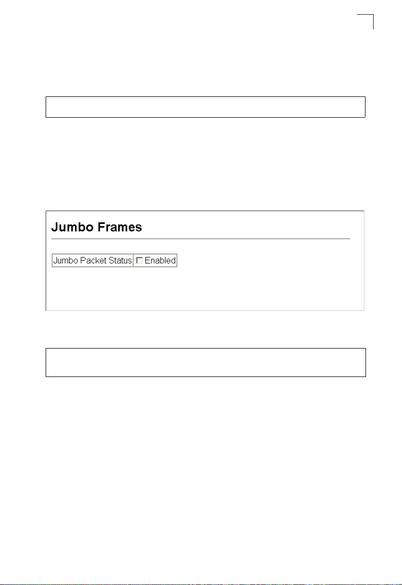
Basic Configuration
Web – If the address assigned by DHCP is no longer functioning, you will not be
able to renew the IP settings via the web interface. You can only restart DHCP
service via the web interface if the current address is still available.
CLI – Enter the following command to restart DHCP service.
Console#ip dhcp restart 4-315
Console#
Enabling Jumbo Frames
You can enable jumbo frames to support data packets up to 9000 bytes in size.
Command Attributes
• Jumbo Packet Status – Check the box to enable jumbo frames.
Web – Click System, Jumbo Frames.
3
Figure 3-8 Jumbo Frames Configuration
CLI – Enter the following command.
Console#config
Console(config)#jumbo frame
Console(config)#
Managing Firmware
You can upload/download firmware to or from a TFTP server, or copy files to and
from switch units in a stack. By saving runtime code to a file on a TFTP server, that
file can later be downloaded to the switch to restore operation. When downloading
runtime code, the new firmware file will overwrite the existing file. You must specify
the method of file transfer, along with the file type and file names as required.
Command Attributes
• File Transfer Method – The firmware copy operation includes these options:
- file to file – Copies a file within the switch directory, assigning it a new name.
- file to tftp – Copies a file from the switch to a TFTP server.
- tftp to file – Copies a file from a TFTP server to the switch.
• TFTP Server IP Address – The IP address of a TFTP server.
3-19
Page 72

Configuring the Switch
3
• File Type – Specify opcode (operational code) to copy firmware.
• File Name –
the file name should not be a period (.), and the maximum length for file names on
the TFTP server is 127 characters or 31 characters for files on the switch.
(Valid characters: A-Z, a-z, 0-9, “.”, “-”, “_”)
Notes: 1.
The file name should not contain slashes (\ or /),
Only one copy of the system software (i.e., the runtime firmware) can be
stored in the file directory on the switch. The currently designated startup
version of this file cannot be deleted.
2. Transferring a new operation code file to the switch will overwrite the existing
file. Versions of the code prior to 1.1.0.3 require the operation code file being
transferred to have the same destination file name as the existing code file
for the transfer to succeed.
the leading letter of
Downloading System Software from a Server
When downloading runtime code, the new operation code file will overwrite the
existing file.
transferred to have the same destination file name as the existing code file for the transfer
to succeed.
Web –Click System, File Management, Copy Operation. Select “tftp to file” as the file
transfer method, enter the IP address of the TFTP server, set the file type to
“opcode,” enter the file name of the software to download, select a file on the switch
to overwrite or specify a new file name, then click Apply. If you replaced the current
firmware used for startup and want to start using the new operation code, reboot the
system via the System/Reset menu.
Versions of the code prior to 1.1.0.3 require the operation code file being
Figure 3-9 Copy Firmware
The new file is automatically set as the startup code since the switch only supports
the presence of one firmware file. After the transfer is complete, restart the system
for the new code to take effect.
3-20
Page 73

Basic Configuration
3
To delete a file, select System, File, Delete. Select the file name from the given list
by checking the tick box and click Apply. Note that t
startup code cannot be deleted.
Figure 3-10 Deleting Files
he file currently designated as the
CLI – To download new firmware from a TFTP server, enter the IP address of the
TFTP server, select “opcode” as the file type, then enter the source and destination
file names. When the file has finished downloading, and then restart the switch for
the new code to take effect.
To start the new firmware, enter the “reload” command or reboot the system.
Console#copy tftp file 4-84
TFTP server ip address: 192.168.1.23
Choose file type:
1. config: 2. opcode: 4. diag: 5. loader: <1,2,4,5>: 2
Source file name: V2.2.7.1.bix
Destination file name: V2271.F
\Write to FLASH Programming.
-Write to FLASH finish.
Success.
Console#config
Console(config)#boot system opcode:V2271.F 4-89
Console(config)#exit
Console#reload 4-22
Saving or Restoring Configuration Settings
You can upload/download configuration settings to/from a TFTP server. The
configuration files can be later downloaded to restore the switch’s settings.
Command Attributes
• File Transfer Method – The configuration copy operation includes these options:
- file to file – Copies a file within the switch directory, assigning it a new name.
- file to running-config – Copies a file in the switch to the running configuration.
- file to startup-config – Copies a file in the switch to the startup configuration.
- file to tftp – Copies a file from the switch to a TFTP server.
- running-config to file – Copies the running configuration to a file.
- running-config to startup-config – Copies the running config to the startup config.
- running-config to tftp – Copies the running configuration to a TFTP server.
- startup-config to file – Copies the startup configuration to a file on the switch.
- startup-config to running-config – Copies the startup config to the running config.
- startup-config to tftp – Copies the startup configuration to a TFTP server.
- tftp to file – Copies a file from a TFTP server to the switch.
3-21
Page 74

Configuring the Switch
3
- tftp to running-config – Copies a file from a TFTP server to the running config.
- tftp to startup-config – Copies a file from a TFTP server to the startup config.
• TFTP Server IP Address – The IP address of a TFTP server.
• File Type – Specify config (configuration) to copy configuration settings.
File Name
•
the file name should not be a period (.), and the maximum length for file names on
the TFTP server is 127 characters or 31 characters for files on the switch. (Valid
characters: A-Z, a-z, 0-9, “.”, “-”, “_”)
Note:
— The file name should not contain slashes (\ or /),
The maximum number of user-defined configuration files is limited only by
available flash memory space.
the leading letter of
Downloading Configuration Settings from a Server
You can download the configuration file under a new file name and then set it as the
startup file, or you can specify the current startup configuration file as the destination
file to directly replace it. Note that the file “Factory_Default_Config.cfg” can be
copied to the TFTP server, but cannot be used as the destination on the switch.
Web – Click System, File, Copy Operation. Select “tftp to startup-config” or “tftp to
file” and enter the IP address of the TFTP server. Specify the name of the file to
download and select a file on the switch to overwrite or specify a new file name, then
click Apply.
Figure 3-11 Downloading Configuration Settings for Startup
If you download to a new file name using “tftp to startup-config” or “tftp to file,” the file
is automatically set as the start-up configuration file. To use the new settings, reboot
the system via the System/Reset menu.
3-22
Page 75

Basic Configuration
3
Note: You can also select any configuration file as the start-up configuration by using the
System/File/Set Start-Up page.
Figure 3-12 Setting the Startup Configuration Settings
CLI – Enter the IP address of the TFTP server, specify the source file on the server,
set the startup file name on the switch, and then restart the switch.
Console#copy tftp startup-config 4-84
TFTP server ip address: 192.168.1.19
Source configuration file name: config-1
Startup configuration file name [] : startup
\Write to FLASH Programming.
-Write to FLASH finish.
Success.
Console#reload
To select another configuration file as the start-up configuration, use the boot
system command and then restart the switch.
Console#config
Console(config)#boot system config: startup-new 4-89
Console(config)#exit
Console#reload 4-22
Console Port Settings
You can access the onboard configuration program by attaching a VT100
compatible device to the switch’s serial console port. Management access through
the console port is controlled by various parameters, including a password, timeouts,
and basic communication settings. These parameters can be configured via the web
or CLI interface.
Command Attributes
• Login Timeout – Sets the interval that the system waits for a user to log into the
CLI. If a login attempt is not detected within the timeout interval, the connection is
terminated for the session. (Range: 0-300 seconds; Default: 0 seconds)
• Exec Timeout – Sets the interval that the system waits until user input is detected.
If user input is not detected within the timeout interval, the current session is
terminated. (Range: 0-65535 seconds; Default: 600 seconds)
• Password Threshold – Sets the password intrusion threshold, which limits the
number of failed logon attempts. When the logon attempt threshold is reached, the
3-23
Page 76
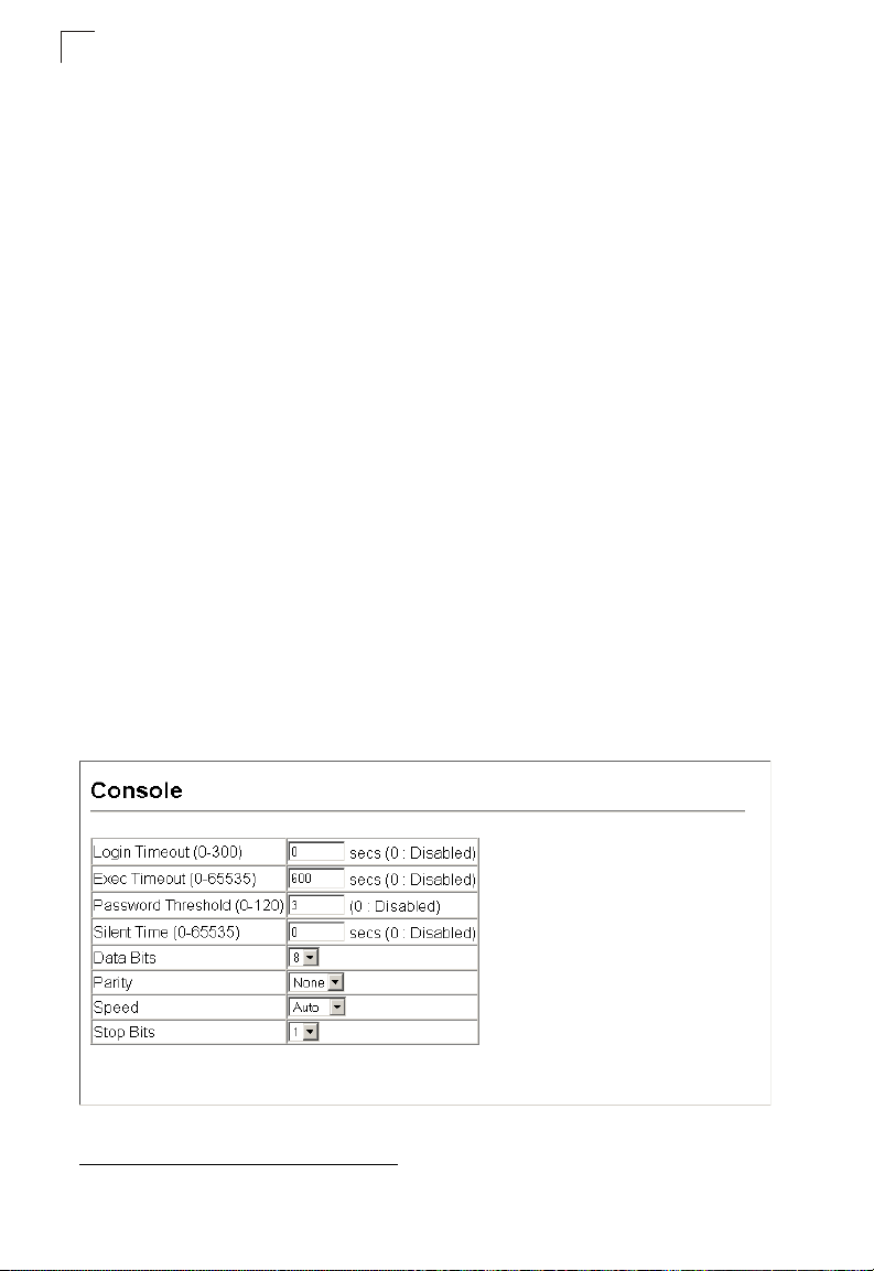
Configuring the Switch
3
system interface becomes silent for a specified amount of time (set by the Silent
Time parameter) before allowing the next logon attempt.
(Range: 0-120; Default: 3 attempts)
• Silent Time – Sets the amount of time the management console is inaccessible
after the number of unsuccessful logon attempts has been exceeded.
(Range: 0-65535; Default: 0)
• Data Bits – Sets the number of data bits per character that are interpreted and
generated by the console port. If parity is being generated, specify 7 data bits per
character. If no parity is required, specify 8 data bits per character. (Default: 8 bits)
• Parity – Defines the generation of a parity bit. Communication protocols provided
by some terminals can require a specific parity bit setting. Specify Even, Odd, or
None. (Default: None)
• Speed – Sets the terminal line’s baud rate for transmit (to terminal) and receive
(from terminal). Set the speed to match the baud rate of the device connected to
the serial port. (Range: 9600, 19200, 38400 baud, or Auto; Default: Auto)
• Stop Bits – Sets the number of the stop bits transmitted per byte.
(Range: 1-2; Default: 1 stop bit)
1
• Password
started on a line with password protection, the system prompts for the password.
If you enter the correct password, the system shows a prompt.
(Default: No password)
• Login
single global password as configured for the Password parameter, or by
passwords set up for specific user-name accounts. (Default: Local)
– Specifies a password for the line connection. When a connection is
1
– Enables password checking at login. You can select authentication by a
Web – Click System, Line, Console. Specify the console port connection parameters
as required, then click Apply.
Figure 3-13 Console Port Settings
1. CLI only.
3-24
Page 77

Basic Configuration
CLI – Enter Line Configuration mode for the console, then specify the connection
parameters as required. To display the current console port settings, use the show
line command from the Normal Exec level.
Console(config)#line console 4-11
Console(config-line)#login local 4-11
Console(config-line)#password 0 secret 4-12
Console(config-line)#timeout login response 0 4-13
Console(config-line)#exec-timeout 0 4-14
Console(config-line)#password-thresh 3 4-14
Console(config-line)#silent-time 60 4-15
Console(config-line)#databits 8 4-16
Console(config-line)#parity none 4-16
Console(config-line)#speed 19200 4-17
Console(config-line)#stopbits 1 4-17
Console(config-line)#end
Console#show line 4-18
Console configuration:
Password threshold: 3 times
Interactive timeout: Disabled
Login timeout: Disabled
Silent time: 60
Baudrate: 19200
Databits: 8
Parity: none
Stopbits: 1
VTY configuration:
Password threshold: 3 times
Interactive timeout: 600 sec
Login timeout: 300 sec
Console#
3
Telnet Settings
You can access the onboard configuration program over the network using Telnet
(i.e., a virtual terminal). Management access via Telnet can be enabled/disabled and
other various parameters set, including the TCP port number, timeouts, and a
password. These parameters can be configured via the web or CLI interface.
Command Attributes
• Telnet Status – Enables or disables Telnet access to the switch.
(Default: Enabled)
• Telnet Port Number – Sets the TCP port number for Telnet on the switch.
(Default: 23)
• Login Timeout – Sets the interval that the system waits for a user to log into the
CLI. If a login attempt is not detected within the timeout interval, the connection is
terminated for the session. (Range: 0-300 seconds; Default: 300 seconds)
• Exec Timeout – Sets the interval that the system waits until user input is detected.
If user input is not detected within the timeout interval, the current session is
terminated. (Range: 0-65535 seconds; Default: 600 seconds)
3-25
Page 78

Configuring the Switch
3
• Password Threshold – Sets the password intrusion threshold, which limits the
number of failed logon attempts. When the logon attempt threshold is reached, the
system interface becomes silent for a specified amount of time (set by the Silent
Time parameter) before allowing the next logon attempt.
(Range: 0-120; Default: 3 attempts)
• Password
started on a line with password protection, the system prompts for the password.
If you enter the correct password, the system shows a prompt. (Default: No
password)
• Login2 – Enables password checking at login. You can select authentication by a
single global password as configured for the Password parameter, or by
passwords set up for specific user-name accounts. (Default: Local)
Web – Click System, Line, Telnet. Specify the connection parameters for Telnet
access, then click Apply.
2
– Specifies a password for the line connection. When a connection is
2. CLI only.
3-26
Figure 3-14 Enabling Telnet
Page 79

Basic Configuration
CLI – Enter Line Configuration mode for a virtual terminal, then specify the
connection parameters as required. To display the current virtual terminal settings,
use the show line command from the Normal Exec level.
Console(config)#line vty 4-11
Console(config-line)#login local 4-11
Console(config-line)#password 0 secret 4-12
Console(config-line)#timeout login response 300 4-13
Console(config-line)#exec-timeout 600 4-14
Console(config-line)#password-thresh 3 4-14
Console(config-line)#end
Console#show line 4-18
Console configuration:
Password threshold: 3 times
Interactive timeout: Disabled
Login timeout: Disabled
Silent time: Disabled
Baudrate: 9600
Databits: 8
Parity: none
Stopbits: 1
VTY configuration:
Password threshold: 3 times
Interactive timeout: 600 sec
Login timeout: 300 sec
Console#
3
3-27
Page 80

Configuring the Switch
3
Configuring Event Logging
The switch allows you to control the logging of error messages, including the type of
events that are recorded in switch memory, logging to a remote System Log (syslog)
server, and displays a list of recent event messages.
Displaying Log Messages
The Logs page allows you to scroll through the logged system and event messages.
The switch can store up to 2048 log entries in temporary random access memory
(RAM; i.e., memory flushed on power reset) and up to 4096 entries in permanent
flash memory.
Web – Click System, Log, Logs.
Figure 3-15 Displaying Logs
CLI – This example shows the event messages stored in RAM.
Console#show log ram 4-58
[1] 00:00:27 2001-01-01
"VLAN 1 link-up notification."
level: 6, module: 5, function: 1, and event no.: 1
[0] 00:00:25 2001-01-01
"System coldStart notification."
level: 6, module: 5, function: 1, and event no.: 1
Console#
System Log Configuration
The system allows you to enable or disable event logging, and specify which levels
are logged to RAM or flash memory.
Severe error messages that are logged to flash memory are permanently stored in
the switch to assist in troubleshooting network problems. Up to 4096 log entries can
be stored in the flash memory, with the oldest entries being overwritten first when the
available log memory (256 kilobytes) has been exceeded.
3-28
Page 81

Basic Configuration
The System Logs page allows you to configure and limit system messages that are
logged to flash or RAM memory. The default is for event levels 0 to 3 to be logged to
flash and levels 0 to 6 to be logged to RAM.
Command Attributes
• System Log Status – Enables/disables the logging of debug or error messages to
the logging process. (Default: Enabled)
• Flash Level – Limits log messages saved to the switch’s permanent flash memory
for all levels up to the specified level. For example, if level 3 is specified, all
messages from level 0 to level 3 will be logged to flash. (Range: 0-7, Default: 3)
Table 3-3 Logging Levels
Level Severity Name Description
7 Debug Debugging messages
6 Informational Informational messages only
5 Notice Normal but significant condition, such as cold start
4 Warning Warning conditions (e.g., return false, unexpected return)
3 Error Error conditions (e.g., invalid input, default used)
2 Critical Critical conditions (e.g., memory allocation, or free memory
error - resource exhausted)
1 Alert Immediate action needed
0 Emergency System unusable
* There are only Level 2, 5 and 6 error messages for the current firmware release.
3
• RAM Level – Limits log messages saved to the switch’s temporary RAM memory
for all levels up to the specified level. For example, if level 7 is specified, all
messages from level 0 to level 7 will be logged to RAM. (Range: 0-7, Default: 6)
The Flash Level must be equal to or less than the RAM Level.
Note:
Web – Click System, Log, System Logs. Specify System Log Status,
event messages to be logged to RAM and flash memory, then click Apply.
Figure 3-16 System Logs
set the level of
3-29
Page 82

Configuring the Switch
3
CLI – Enable system logging and then specify the level of messages to be logged to
RAM and flash memory. Use the show logging command to display the current
settings.
Console(config)#logging on 4-54
Console(config)#logging history ram 0 4-55
Console(config)#end
Console#show logging flash 4-58
Syslog logging: Enabled
History logging in FLASH: level emergencies
Console#
Remote Log Configuration
The Remote Logs page allows you to configure the logging of messages that are
sent to syslog servers or other management stations. You can also limit the error
messages sent to only those messages below a specified level.
Command Attributes
• Remote Log Status – Enables/disables the logging of debug or error messages
to the remote logging process. (Default: Enabled)
• Logging Facility – Sets the facility type for remote logging of syslog messages.
There are eight facility types specified by values of 16 to 23. The facility type is
used by the syslog server to dispatch log messages to an appropriate service.
The attribute specifies the facility type tag sent in syslog messages. (See RFC
3164.) This type has no effect on the kind of messages reported by the switch.
However, it may be used by the syslog server to process messages, such as
sorting or storing messages in the corresponding database. (Range: 16-23,
Default: 23)
• Logging Trap – Limits log messages that are sent to the remote syslog server for
all levels up to the specified level. For example, if level 3 is specified, all messages
from level 0 to level 3 will be sent to the remote server. (Range: 0-7, Default: 6)
• Host IP List – Displays the list of remote server IP addresses that receive the
syslog messages. The maximum number of host IP addresses allowed is five.
• Host IP Address – Specifies a new server IP address to add to the Host IP List.
3-30
Page 83

Basic Configuration
Web – Click System, Log, Remote Logs. To add an IP address to the Host IP List,
type the new IP address in the Host IP Address box, and then click Add. To delete
an IP address, click the entry in the Host IP List, and then click Remove.
Figure 3-17 Remote Logs
CLI – Enter the syslog server host IP address, choose the facility type and set the
logging trap.
Console(config)#logging host 192.168.1.15 4-56
Console(config)#logging facility 23 4-56
Console(config)#logging trap 4 4-57
Console(config)#end
Console#show logging trap 4-57
Syslog logging: Enabled
REMOTELOG status: Enabled
REMOTELOG facility type: local use 7
REMOTELOG level type: Warning conditions
REMOTELOG server ip address: 192.168.1.15
REMOTELOG server ip address: 0.0.0.0
REMOTELOG server ip address: 0.0.0.0
REMOTELOG server ip address: 0.0.0.0
REMOTELOG server ip address: 0.0.0.0
Console#
3
3-31
Page 84

Configuring the Switch
3
Simple Mail Transfer Protocol
SMTP (Simple Mail Transfer Protocol) is used to send email messages between
servers. The messages can be retrieved using POP or IMAP clients.
Command Attributes
• Admin Status – Enables/disables the SMTP function. (Default: Enabled)
• Email Source Address – This command specifies SMTP servers email addresses
that can send alert messages.
• Severity – Specifies the degree of urgency that the message carries.
• Debugging – Sends a debugging notification. (Level 7)
• Information – Sends informatative notification only. (Level 6)
• Notice – Sends notification of a normal but significant condition, such as a cold
start. (Level 5)
• Warning – Sends notification of a warning condition such as return false, or
unexpected return. (Level 4)
• Error – Sends notification that an error conditions has occurred, such as invalid
input, or default used. (Level 3)
• Critical – Sends notification that a critical condition has occurred, such as
memory allocation, or free memory error - resource exhausted. (Level 2)
• Alert – Sends urgent notification that immediate action must be taken. (Level 1)
• Emergency – Sends an emergency notification that the system is now unusable.
(Level 0)
• SMTP Server List – Specifies a list of recipient SMTP servers.
• SMTP Server – Specifies a new SMTP server address to add to the SMTP Server
List.
• Email Destination Address List – Specifies a list of recipient Email Destination
Address.
• Email Destination Address – This command specifies SMTP servers that may
receive alert messages.
3-32
Page 85
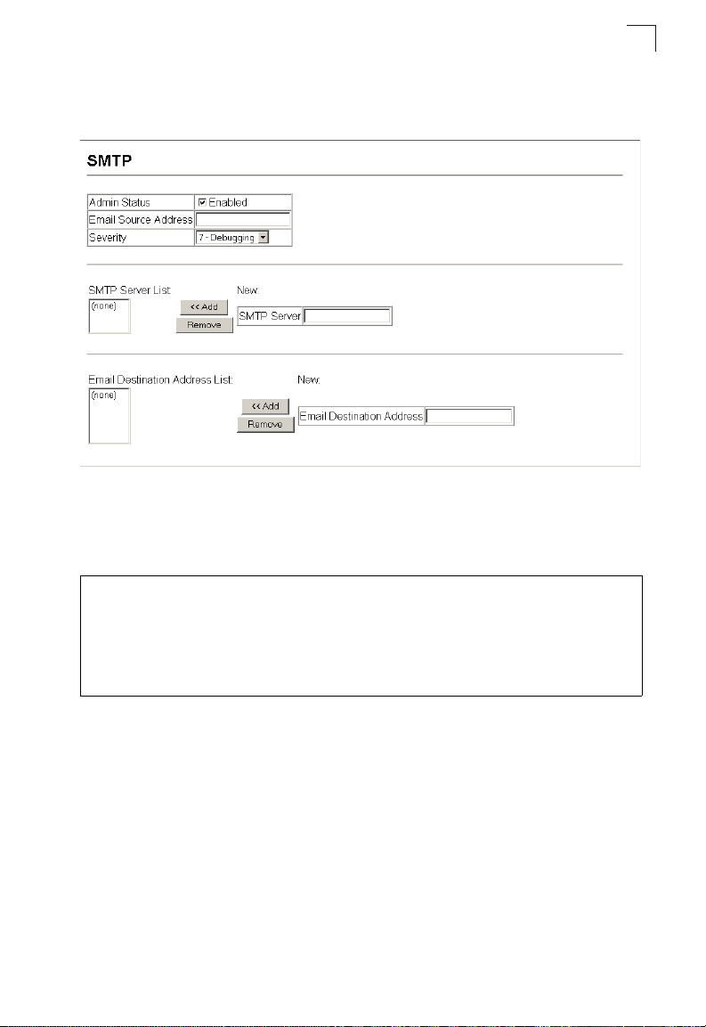
Basic Configuration
3
Web – Click System, Log, SMTP. To add an IP address to the Server IP List, type
the new IP address in the Server IP Address box, and then click Add. To delete an IP
address, click the entry in the Server IP List, and then click Remove.
Figure 3-18 Enabling and Configuring SMTP
CLI – Enter the host ip address, followed by the mail severity level, source and
destination email addresses and enter the sendmail command to complete the
action. Use the show logging command to display SMTP information.
Console(config)#logging sendmail host 192.168.1.19
Console(config)#logging sendmail level 3
Console(config)#logging sendmail source-email
bill@this-company.com
Console(config)#logging sendmail destination-email
ted@this-company.com
Console(config)#logging sendmail
Console#
3-33
Page 86

Configuring the Switch
3
Resetting the System
This feature restarts the system. You can reboot the system immediately, or you can
configure the switch to reset after a specified amount of time.
Command Attributes
• Hours – Specifies the amount of hours to wait, combined with the minutes, before
the switch resets. (Range: 0-576; Default: 0)
• Minutes – Specifies the amount of minutes to wait, combined with the hours,
before the switch resets. (Range: 1-34560; Default: 0)
• Reset – Resets the switch after the specified time. If the hour and minute fields are
blank, then the switch will reset immediately.
• Refresh – Refreshes the countdown timer of a pending delayed reset.
• Cancel – Cancels a pending delayed reset.
Web – Click System, Reset. Enter the amount of time the switch should wait before
rebooting. Click the Reset button to reboot the switch or click the Cancel button to
cancel a configured reset. If prompted, confirm that you want reset the switch or
cancel a configured reset.
Figure 3-19 Resetting the System
CLI – Use the reload command to restart the switch. When prompted, confirm that
you want to reset the switch.
Console#reload 4-22
System will be restarted, continue <y/n>? y
When restarting the system, it will always run the Power-On Self-Test. It will also
Note:
retain all configuration information stored in non-volatile memory (See “Saving or
Restoring Configuration Settings” on page 3-21 or the copy running-config
startup-config command (See “copy” on page 4-84)).
3-34
Page 87
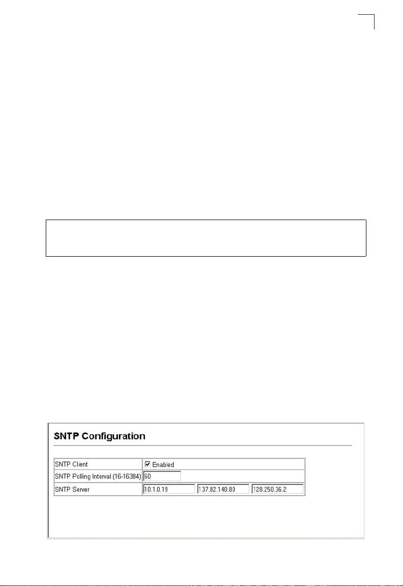
Basic Configuration
3
Setting the System Clock
Simple Network Time Protocol (SNTP) allows the switch to set its internal clock
based on periodic updates from a time server (SNTP or NTP). Maintaining an
accurate time on the switch enables the system log to record meaningful dates and
times for event entries. You can also manually set the clock. If the clock is not set,
the switch will only record the time from the factory default set at the last bootup.
When the SNTP client is enabled, the switch periodically sends a request for a time
update to a configured time server. You can configure up to three time server IP
addresses. The switch will attempt to poll each server in the configured sequence.
Setting the Time Manually
You can set the system time on the switch manually without using SNTP.
CLI – This example sets the system clock time and then displays the current time
and date.
Console#calendar set 17 46 00 october 18 2007 4-76
Console#show calendar 4-76
17:46:11 October 18 2007
Console#
Configuring SNTP
You can configure the switch to send time synchronization requests to time servers.
Command Attributes
• SNTP Client – Configures the switch to operate as an SNTP client. This requires
at least one time server to be specified in the SNTP Server field. (Default: Disabled)
• SNTP Poll Interval – Sets the interval between sending requests for a time update
from a time server. (Range: 16-16384 seconds; Default: 16 seconds)
• SNTP Server – Sets the IP address for up to three time servers. The switch
attempts to update the time from the first server, if this fails it attempts an update
from the next server in the sequence.
Web – Select SNTP, Configuration. Modify any of the required SNTP parameters,
and click Apply.
3-35
Page 88

Configuring the Switch
3
Figure 3-20 SNTP Configuration
CLI – This example configures the switch to operate as an SNTP unicast client and
then displays the current time and settings.
Console(config)#sntp server 10.1.0.19 137.82.140.80 128.250.36.2 4-65
Console(config)#sntp poll 60 4-66
Console(config)#sntp client 4-64
Console(config)#exit
Console#show sntp
Current time: Jan 6 14:56:05 2004
Poll interval: 60
Current mode: unicast
SNTP status : Enabled
SNTP server 10.1.0.19 137.82.140.80 128.250.36.2
Current server: 128.250.36.2
Console#
Configuring NTP
The NTP client allows you to configure up to 50 NTP servers to poll for time updates.
You can also enable authentication to ensure that reliable updates are received from
only authorized NTP servers. The authentication keys and their associated key
number must be centrally managed and manually distributed to NTP servers and
clients. The key numbers and key values must match on both the server and client.
Command Attributes
• NTP Client – Configures the switch to operate as an NTP client. This requires at
least one time server to be specified in the NTP Server list. (Default: Disabled)
• NTP Polling Interval – Sets the interval between sending requests for a time
update from NTP servers. (Range: 16-16384 seconds; Default: 16 seconds)
• NTP Authenticate – Enables authentication for time requests and updates
between the switch and NTP servers. (Default: Disabled)
• NTP Server – Sets the IP address for an NTP server to be polled. The switch
requests an update from all configured servers, then determines the most accurate
time update from the responses received.
• Version – Specifies the NTP version supported by the server. (Range: 1-3;
Default: 3)
• Authenticate Key – Specifies the number of the key in the NTP Authentication Key
List to use for authentication with the configured server. The authentication key
must match the key configured on the NTP server.
• Key Number – A number that specifies a key value in the NTP Authentication Key
List. Up to 255 keys can be configured in the NTP Authentication Key List. Note
that key numbers and values must match on both the server and client. (Range:
1-65535)
• Key Context – Specifies an MD5 authentication key string. The key string can be
up to 32 case-sensitive printable ASCII characters (no spaces).
3-36
Page 89

Basic Configuration
3
Web – Select SNTP, Configuration. Modify any of the required NTP parameters, and
click Apply.
Figure 3-21 NTP Client Configuration
CLI – This example configures the switch to operate as an NTP client and then
displays the current settings.
Console(config)#ntp authentication-key 19 md5 thisiskey19 4-70
Console(config)#ntp authentication-key 30 md5 ntpkey30
Console(config)#ntp server 192.168.3.20 4-68
Console(config)#ntp server 192.168.3.21
Console(config)#ntp server 192.168.4.22 version 2
Console(config)#ntp server 192.168.5.23 version 3 key 19
Console(config)#ntp poll 60 4-69
Console(config)#ntp client 4-67
Console(config)#ntp authenticate 4-69
Console(config)#exit
Console#show ntp 4-71
Current time: Jan 1 02:58:58 2001
Poll interval: 60
Current mode: unicast
NTP status : Enabled NTP Authenticate status : Enabled
Last Update NTP Server: 0.0.0.0 Port: 0
Last Update time: Dec 31 00:00:00 2000 UTC
NTP Server 192.168.3.20 version 3
NTP Server 192.168.3.21 version 3
NTP Server 192.168.4.22 version 2
NTP Server 192.168.5.23 version 3 key 19
NTP Authentication-Key 19 md5 Q33O16Q6338241J022S29Q731K7 7
NTP Authentication-Key 30 md5 D2V8777I51K1132K3552L26R6141O4 7
Console#
3-37
Page 90

Configuring the Switch
3
Setting the Time Zone
SNTP uses Coordinated Universal Time (or UTC, formerly Greenwich Mean Time,
or GMT) based on the time at the Earth’s prime meridian, zero degrees longitude,
which passes through Greenwich, England. To display a time corresponding to your
local time, you must indicate the number of hours and minutes your time zone is
east (before) or west (after) of UTC. You can choose one of the 80 predefined time
zone definitions, or your can manually configure the parameters for your local time
zone.
Command Attributes
• Predefined Configuration – A drop-down box provides access to the 80
predefined time zone configurations. Each choice indicates it’s offset from UTC
and lists at least one major city or location covered by the time zone.
• User-defined Configuration – Allows the user to define all parameters of the local
time zone.
• Direction: Configures the time zone to be before (east) or after (west) UTC.
• Name – Assigns a name to the time zone. (Range: 1-29 characters)
• Hours (0-13) – The number of hours before/after UTC. The maximum value before
UTC is 12. The maximum value after UTC is 13.
• Minutes (0-59) – The number of minutes before/after UTC.
Web – Select SNTP, Clock Time Zone. Set the offset for your time zone relative to
the UTC using either a predefined or custom definition, and click Apply.
Figure 3-22 Setting the System Clock
CLI - This example shows how to set the time zone for the system clock using one of
the predefined time zone configurations.
Console(config)#clock timezone-predefined GMT-0930-Taiohae 4-71
Console(config)#
3-38
Page 91

Simple Network Management Protocol
3
Simple Network Management Protocol
SNMP is a communication protocol designed specifically for managing devices on a
network. Equipment commonly managed with SNMP includes switches, routers and
host computers. SNMP is typically used to configure these devices for proper
operation in a network environment, as well as to monitor them to evaluate
performance or detect potential problems.
Managed devices supporting SNMP contain software, which runs locally on the
device and is referred to as an agent. A defined set of variables, known as managed
objects, is maintained by the SNMP agent and used to manage the device. These
objects are defined in a Management Information Base (MIB) that provides a
standard presentation of the information controlled by the agent. SNMP defines both
the format of the MIB specifications and the protocol used to access this information
over the network.
The switch includes an onboard agent that supports SNMP versions 1, 2c, and 3.
This agent continuously monitors the status of the switch hardware, as well as the
traffic passing through its ports. A network management station can access this
information using software such as HP OpenView. Access to the onboard agent
from clients using SNMP v1 and v2c is controlled by community strings. To
communicate with the switch, the management station must first submit a valid
community string for authentication.
Access to the switch using from clients using SNMPv3 provides additional security
features that cover message integrity, authentication, and encryption; as well as
controlling user access to specific areas of the MIB tree.
The SNMPv3 security structure consists of security models, with each model having
it’s own security levels. There are three security models defined, SNMPv1,
SNMPv2c, and SNMPv3. Users are assigned to “groups” that are defined by a
security model and specified security levels. Each group also has a defined security
access to set of MIB objects for reading and writing, which are known as “views.”
The switch has a default view (all MIB objects) and default groups defined for
security models v1 and v2c. The following table shows the security models and
levels available and the system default settings.
3-39
Page 92

Configuring the Switch
3
Table 3-4 SNMPv3 Security Models and Levels
Model Level Group Read View Write View Notify View Security
v1 noAuthNoPriv public
v1 noAuthNoPriv private
v1 noAuthNoPriv user defined user defined user defined user defined Community string only
v2c noAuthNoPriv public
v2c noAuthNoPriv private
v2c noAuthNoPriv user defined user defined user defined user defined Community string only
v3 noAuthNoPriv user defined user defined user defined user defined A user name match only
v3 AuthNoPriv user defined user defined user defined user defined Provides user
v3 AuthPriv user defined user defined user defined user defined Provides user
Note: The predefined default groups and view can be deleted from the system. You can
then define customized groups and views for the SNMP clients that require access.
(read only)
(read/write)
(read only)
(read/write)
defaultview none none Community string only
defaultview defaultview none Community string only
defaultview none none Community string only
defaultview defaultview none Community string only
authentication via MD5 or
SHA algorithms
authentication via MD5 or
SHA algorithms and data
privacy using DES 56-bit
encryption
Setting Community Access Strings
You may configure up to five community strings authorized for management access.
All community strings used for IP Trap Managers should be listed in this table. For
security reasons, you should consider removing the default strings.
Command Attributes
• SNMP Community Capability – Indicates that the switch supports up to five
community strings.
• Community String – A community string that acts like a password and permits
access to the SNMP protocol.
Default strings: “public” (read-only), “private” (read/write)
Range: 1-32 characters, case sensitive
• Access Mode
- Read-Only – Specifies read-only access. Authorized management stations are
only able to retrieve MIB objects.
- Read/Write – Specifies read-write access. Authorized management stations are
able to both retrieve and modify MIB objects.
3-40
Page 93

Simple Network Management Protocol
Web – Click SNMP, Configuration. Add new community strings as required, select
the access rights from the Access Mode drop-down list, then click Add.
Figure 3-23 Configuring SNMP Community Strings
CLI – The following example adds the string “spiderman” with read/write access.
Console(config)#snmp-server community spiderman rw 4-152
Console(config)#
3
Specifying Trap Managers and Trap Types
Traps indicating status changes are issued by the switch to specified trap managers.
You must specify trap managers so that key events are reported by this switch to
your management station (using network management platforms such as HP
OpenView). You can specify up to five management stations that will receive
authentication failure messages and other trap messages from the switch.
Command Attributes
• Trap Manager Capability – This switch supports up to five trap managers.
• Current – Displays a list of the trap managers currently configured.
• Trap Manager IP Address – IP address of the host (the targeted recipient).
• Trap Manager Community String – Community string sent with the notification
operation. (Range: 1-32 characters, case sensitive)
• Trap UDP Port – Sets the UDP port number. (Default: 162)
• Trap Version – Specifies whether to send notifications as SNMP v1, v2c, or v3
traps. (The default is version 1.)
• Trap Security Level – Specifies the security level.
• Enable Authentication Traps – Issues a trap message whenever an invalid
community string is submitted during the SNMP access authentication process.
(Default: Enabled)
• Enable Link-up and Link-down Traps – Issues a trap message whenever a port
link is established or broken. (Default: Enabled)
3-41
Page 94

Configuring the Switch
3
Web – Click SNMP, Configuration. Fill in the IP address and community string for
each trap manager that will receive trap messages, and then click Add. Select the
trap types required using the check boxes for Authentication and Link-up/down
traps, and then click Apply.
Figure 3-24 Configuring IP Trap Managers
CLI – This example adds a trap manager and enables both authentication and
link-up, link-down traps.
Console(config)#snmp-server host 192.168.1.19 private version 2c 4-153
Console(config)#snmp-server enable traps 4-155
Enabling SNMP Agent Status
Enables SNMPv3 service for all management clients (i.e., versions 1, 2c, 3).
Command Attributes
• SNMP Agent Status – Check the box to enable or disable the SNMP Agent.
Web – Click SNMP, Agent Status.
Figure 3-25 Enabling SNMP Agent Status
3-42
Page 95

Simple Network Management Protocol
3
Configuring SNMPv3 Management Access
To configure SNMPv3 management access to the switch, follow these steps:
1. If you want to change the default engine ID, it must be changed first before
configuring other parameters.
2. Specify read and write access views for the switch MIB tree.
3. Configure SNMP user groups with the required security model (i.e., SNMP v1,
v2c or v3) and security level (i.e., authentication and privacy).
4. Assign SNMP users to groups, along with their specific authentication and
privacy passwords.
Setting the Local Engine ID
An SNMPv3 engine is an independent SNMP agent that resides on the switch. This
engine protects against message replay, delay, and redirection. The engine ID is
also used in combination with user passwords to generate the security keys for
authenticating and encrypting SNMPv3 packets.
A local engine ID is automatically generated that is unique to the switch. This is
referred to as the default engine ID. If the local engine ID is deleted or changed, all
SNMP users will be cleared. You will need to reconfigure all existing users.
A new engine ID can be specified by entering 9 to 64 hexadecimal characters (5 to
32 octets in hexadecimal format). If an odd number of characters are specified, a
trailing zero is added to the value to fill in the last octet. For example, the value
“123456789” is equivalent to “1234567890”.
Web – Click SNMP, SNMPv3, Engine ID.
Figure 3-26 Setting an Engine ID
3-43
Page 96
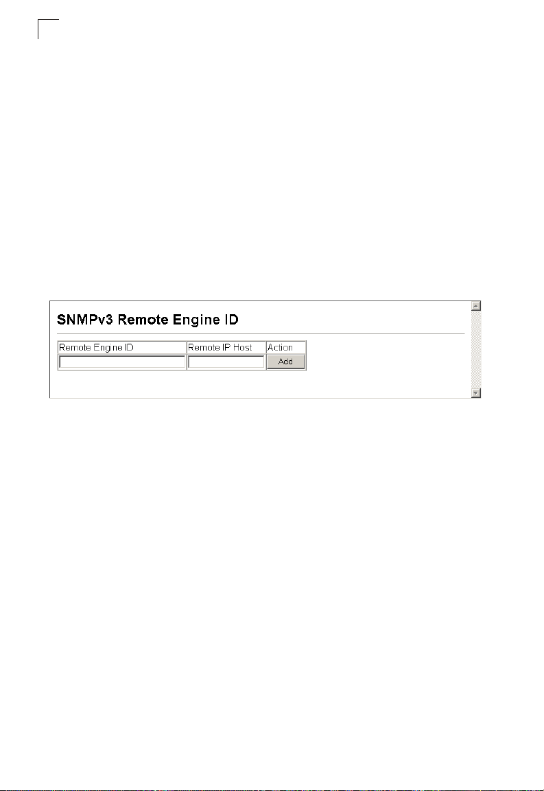
Configuring the Switch
3
Specifying a Remote Engine ID
To send inform messages to an SNMPv3 user on a remote device, you must first
specify the engine identifier for the SNMP agent on the remote device where the
user resides. The remote engine ID is used to compute the security digest for
authenticating and encrypting packets sent to a user on the remote host.
SNMP passwords are localized using the engine ID of the authoritative agent. For
informs, the authoritative SNMP agent is the remote agent. You therefore need to
configure the remote agent’s SNMP engine ID before you can send proxy requests
or informs to it.
The engine ID can be specified by entering 9 to 64 hexadecimal characters (5 to 32
octets in hexadecimal format). If an odd number of characters are specified, a
trailing zero is added to the value to fill in the last octet. For example, the value
“123456789” is equivalent to “1234567890”.
Web – Click SNMP, SNMPv3, Remote Engine ID.
Figure 3-27 Setting a Remote Engine ID
Configuring SNMPv3 Users
Each SNMPv3 user is defined by a unique name. Users must be configured with a
specific security level and assigned to a group. The SNMPv3 group restricts users to
a specific read, write, and notify view.
Command Attributes
• User Name – The name of user connecting to the SNMP agent.
(Range: 1-32 characters)
• Group Name – The name of the SNMP group to which the user is assigned.
(Range: 1-32 characters)
• Model – The user security model; SNMP v1, v2c or v3.
• Level – The security level used for the user:
- noAuthNoPriv – There is no authentication or encryption used in SNMP
communications. (This is the default for SNMPv3.)
- AuthNoPriv – SNMP communications use authentication, but the data is not
encrypted (only available for the SNMPv3 security model).
- AuthPriv – SNMP communications use both authentication and encryption (only
available for the SNMPv3 security model).
• Authentication – The method used for user authentication.
(Options: MD5, SHA; Default: MD5)
3-44
Page 97
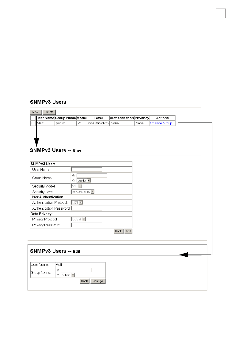
Simple Network Management Protocol
• Authentication Password – A minimum of eight plain text characters is required.
• Privacy – The encryption algorithm use for data privacy; only 56-bit DES is
currently available.
• Actions – Enables the user to be assigned to another SNMPv3 group.
Web – Click SNMP, SNMPv3, Users. Click New to configure a user name. In the
New User page, define a name and assign it to a group, then click Add to save the
configuration and return to the User Name list. To delete a user, check the box next
to the user name, then click Delete. To change the assigned group of a user, click
Change Group in the Actions column of the users table and select the new group.
3
Figure 3-28 Configuring SNMPv3 Users
3-45
Page 98

Configuring the Switch
3
Configuring Remote SNMPv3 Users
Each SNMPv3 user is defined by a unique name. Users must be configured with a
specific security level and assigned to a group. The SNMPv3 group restricts users to
a specific read, write, and notify view.
To send inform messages to an SNMPv3 user on a remote device, you must first
specify the engine identifier for the SNMP agent on the remote device where the
user resides. The remote engine ID is used to compute the security digest for
authenticating and encrypting packets sent to a user on the remote host.
Command Attributes
• User Name – The name of user connecting to the SNMP agent.
(Range: 1-32 characters)
• Group Name – The name of the SNMP group to which the user is assigned.
(Range: 1-32 characters)
• Engine ID – The engine identifier for the SNMP agent on the remote device where
the remote user resides. Note that the remote engine identifier must be specified
before you configure a remote user. (See “Specifying a Remote Engine ID” on
page 44.)
• Model – The user security model; SNMP v1, v2c or v3.
• Level – The security level used for the user:
- noAuthNoPriv – There is no authentication or encryption used in SNMP
communications. (This is the default for SNMPv3.)
- AuthNoPriv – SNMP communications use authentication, but the data is not
encrypted (only available for the SNMPv3 security model).
- AuthPriv – SNMP communications use both authentication and encryption (only
available for the SNMPv3 security model).
• Authentication – The method used for user authentication.
(Options: MD5, SHA; Default: MD5)
• Privacy – The encryption algorithm use for data privacy; only 56-bit DES is
currently available.
Web – Click SNMP, SNMPv3, Remote Users. Click New to configure a user name.
In the New User page, define a name and assign it to a group, then click Add to save
the configuration and return to the User Name list. To delete a user, check the box
next to the user name, then click Delete.
Figure 3-29 Configuring Remote SNMPv3 Users
3-46
Page 99

Simple Network Management Protocol
3
Configuring SNMPv3 Groups
An SNMPv3 group sets the access policy for its assigned users, restricting them to
specific read, write, and notify views. You can use the pre-defined default groups or
create new groups to map a set of SNMP users to SNMP views.
Command Attributes
• Group Name – The name of the SNMP group to which the user is assigned.
(Range: 1-32 characters)
• Model – The user security model; SNMP v1, v2c or v3.
• Level – The security level used for the group:
- noAuthNoPriv – There is no authentication or encryption used in SNMP
communications. (This is the default for SNMPv3.)
- AuthNoPriv – SNMP communications use authentication, but the data is not
encrypted (only available for the SNMPv3 security model).
- AuthPriv – SNMP communications use both authentication and encryption (only
available for the SNMPv3 security model).
• Read View – The configured view for read access. (Range: 1-64 characters)
• Write View – The configured view for write access. (Range: 1-64 characters)
• Notify View – The configured view for notifications. (Range: 1-64 characters)
Table 3-5 Supported Notification Messages
Object Label Object ID Description
RFC 1493 Traps
newRoot 1.3.6.1.2.1.17.0.1 The newRoot trap indicates that the sending
topologyChange 1.3.6.1.2.1.17.0.2 A topologyChange trap is sent by a bridge
SNMPv2 Traps
coldStart 1.3.6.1.6.3.1.1.5.1 A coldStart trap signifies that the SNMPv2
warmStart 1.3.6.1.6.3.1.1.5.2 A warmStart trap signifies that the SNMPv2
agent has become the new root of the
Spanning Tree; the trap is sent by a bridge
soon after its election as the new root, e.g.,
upon expiration of the Topology Change
Timer immediately subsequent to its election.
when any of its configured ports transitions
from the Learning state to the Forwarding
state, or from the Forwarding state to the
Discarding state. The trap is not sent if a
newRoot trap is sent for the same transition.
entity, acting in an agent role, is reinitializing
itself and that its configuration may have
been altered.
entity, acting in an agent role, is reinitializing
itself such that its configuration is unaltered.
3-47
Page 100

Configuring the Switch
3
Table 3-5 Supported Notification Messages (Continued)
Object Label Object ID Description
a
linkDown
linkUp 1.3.6.1.6.3.1.1.5.4 A linkUp trap signifies that the SNMP entity,
authenticationFailure 1.3.6.1.6.3.1.1.5.5 An authenticationFailure trap signifies that
RMON Events (V2)
risingAlarm 1.3.6.1.2.1.16.0.1 The SNMP trap that is generated when an
fallingAlarm 1.3.6.1.2.1.16.0.2 The SNMP trap that is generated when an
Private Traps
swPowerStatus
ChangeTrap
swIpFilterRejectTrap 1.3.6.1.4.1.202.20.65. 2.1.0.40 This trap is sent when an inco rrect IP address
pethPsePortOnOff
Notification
pethPsePortPower
MaintenanceStatus
Notification
1.3.6.1.6.3.1.1.5.3 A linkDown trap signifies that the SNMP
1.3.6.1.4.1.202.20.65.2.1.0.1 This trap is sent when the power state
1.3.6.1.4.1.202.20.65.173.2.1.0.43 This notification indicates if a PSE (Power
1.3.6.1.4.1.202.20.65.173.2.1.0.44 This notification indicates a Port Change
entity, acting in an agent role, has detected
that the ifOperStatus object for one of its
communication links is about to enter the
down state from some other state (but not
from the notPresent state). This other state is
indicated by the included value of
ifOperStatus.
acting in an agent role, has detected that the
ifOperStatus object for one of its
communication links left the down state and
transitioned into some other state (but not
into the notPresent state). This other state is
indicated by the included value of
ifOperStatus.
the SNMPv2 entity, acting in an agent role,
has received a protocol message that is not
properly authenticated. While all
implementations of the SNMPv2 must be
capable of generating this trap, the
snmpEnableAuthenTraps object indicates
whether this trap will be generated.
alarm entry crosses its rising threshold and
generates an event that is configured for
sending SNMP traps.
alarm entry crosses its falling threshold and
generates an event that is configured for
sending SNMP traps.
changes.
is rejected by the IP Filter.
Sourcing Equipment) Port is delivering power
to the PD (Powered Device). This notification
is sent on every status change except in
search mode.
Status and is sent on every status change.
3-48
 Loading...