

Page 1

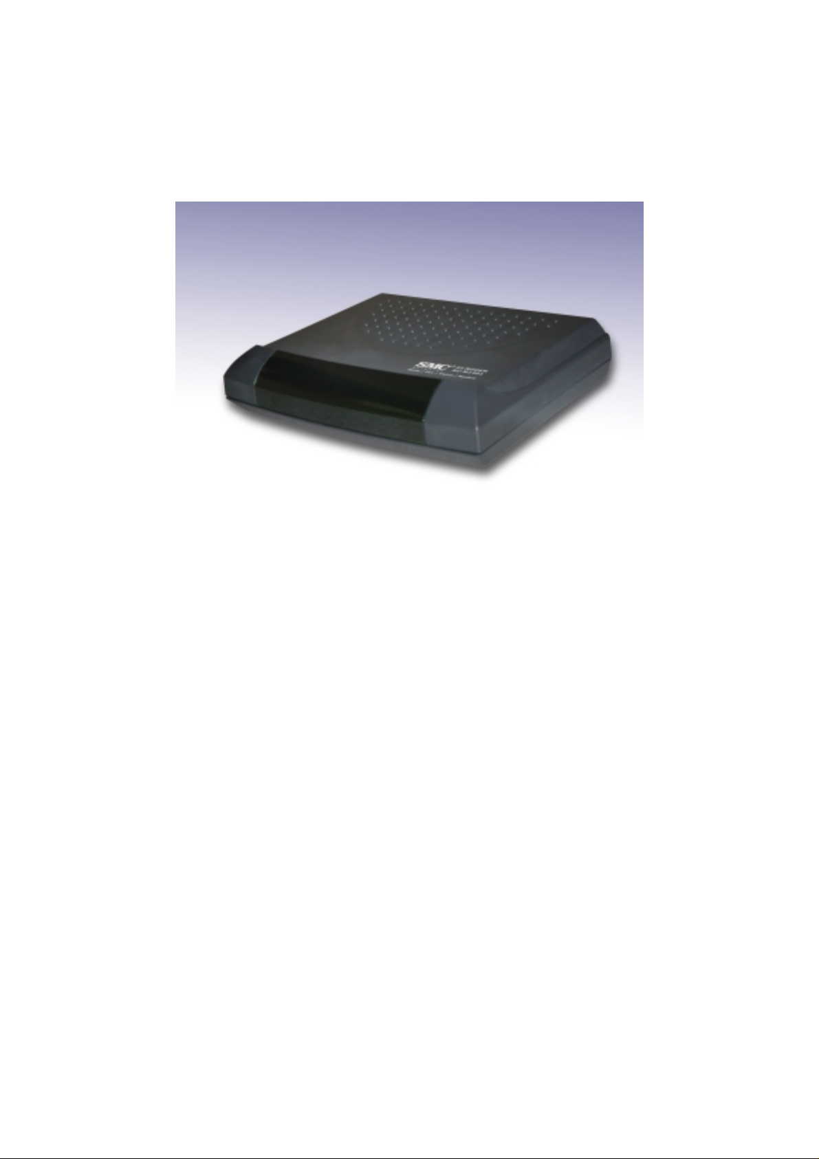
EZ Modem SMC3056EM
External Data/Fax/Voice Modem
User Guide
1 Claymore Drive #08-05/06
Orchard Tower (Rear Blk) Singapore 22 9594 October 200 2
Phone:+65 62386556 Rev ision Number:R0 1
1
Page 2

FCC Requirements
This equipment complies with Part 68 of the FCC Rules. On the bottom of this equipment is a
label that contains, among other information, the FCC Registration Number and Ringer
Equivalence Number (REN) for this equipment. IF REQUESTED. THIS INFORMATION
MUST BE GIVEN TO THE TELEPHONE COMPANY.
The REN is usef ul to de te rmine the quantity of devices you may connec t to your telephone line
and still have these entire devices ring when your telephone number is called In most. But not
all areas the sum of the REN’s of all devices connected to one line should not exceed five (5.0).
T o be certa in of the num ber of device s you may c onnect to your line. As de termined by the REN.
You should contact your local telephone company to determine the maximum REN of the area
you are calling from. If your telephone equipment causes harm to the telephone network. The
T e le phone Company may discontinue your service tempora lly. If possible, they will notify y ou
in advance. But if the advanced notice is failed, you will be notified as soon as possible. You
will be informed of your right to file a complaint with the FCC.
Your telephone company may change in its facilities, equipment, operations or procedures that
could affect the proper functions of your equipment. If this occurs, you will be notified in
advance to give you an opportunity to maintain uninterrupted telephone service.
If you experience trouble with this telephone equipment, please contact the following address
and phone number for information on obtaining service or repairs. The Telephone Company
may ask you to disc on ne ct this equipment from the network until th e pro blem is solved or until
that the equipment is not detected malfunctioning. This equipment may not be used on coin
service provided by the Telephone Company. Connection to party lines is subject to state
Tariffs.
Federal Communications Commission
Radio Frequency Interference Statement
Note: This equipment has been tested and found to comply with the limitation for a lass B
digital device pursua nt to Part 15 of the FCC Rules. The se r e st ric t ions ar e de s igned to provide
reasonable protection against harmful interference when the equipment is operated in a
residential installa tion. T his e quipm e nt ge nera tes, us es, a nd ca n ra diate radi o f reque ncy ene rgy
and if not installed and used in accordan ce with the instruction manu al may cause harmful
interference to radio comm unications. How ever, there is no guara ntee that interf erence will not
occur in a particular installation. If the equipment does cause harmful interference to radio or
television reception, which can be determine by tuning the equipment o ff and on, the user is
suggested to try to correct th e interference by one or more of the followin g measures:
-Reorient or relocate the receiving antenna.
-Increase the distance between the equipment and receiver.
-Connect the equi pment into an outl et on a circuit different from that to which t he receiver
is connected. Con sult the dealer or an experienced radio TV tech nician for help.
Notices:
(1) The changes or modifications not expressly approved by the party responsible for
compliance could void the user’s authority to operate the equipment.
(2) Shielded interface cables and AC power cord if any must be used in order to comply with
the emission limits.
.
2
Page 3

CO
Notices to Australian users:
The modem card must only be used in a data terminal equipment (DTE) e.g. computer, that has
a screw down cover (lid). As unsafe voltages (TNV) exist on the modem card, disconnect the
modem card from the telephone line while the cover (lid) of the DTE (computer) is removed.
Installation of the modem card in a DTE (computer) which does not require a tool to open the
cover (lid) will render the permit void.
Disconnect the telephone line before opening the cover (lid) of the DTE (computer). Do not
connect the customer equipment to the telephone line while the cover (lid) of the DTE
(computer) is open.
Modems connected to the Australian telecommunications network must be marked in
accordance with the Labelin g Notice. This mode m has been specifi cally configured to ensure
compliance with the A CA Sta ndards. Do not a djust y our m odem or softwa re outs ide the value s
indicated as below. To do so would result in your modem being operated in a non-compliant
manner.
Modem Commands:
Command
ATA - Do not use
ATB B0 Do not set to B1
AT&G &G0 &G2
AT&P &P0 &P1
ATSn see table below
S register
s6 2 2 to 6
Call Attempts/Retries:
Applications software shall be configured so that no more than 3 attempts are made to
establish a connection to a given number (Note: if the modem can detect service tones, up to
10 attempts can be made). If the call sequence is unsuccessful, there shall be a delay of at least
30 minutes before attempting to call the number again.
Failure to set the modem and any application software used with the modem, to the values
shown as above will result in the modem being operated in a non-compliant manner.
Consequently, this would be in violation of the Labeling Notice for this equipment, and the
Telecommunications ACT 1997 prescribes penalties for the connection of non-compliant
equipment.
ONLY CONNECT EQUIPMENT WITH A TELECOMMUNICATIONS
FOR SAFETY REASONS, ONLY CONNECT EQUIPMENT WITH A
TELECOMMUNICATIOS COMPLIANCE LABEL. THIS INCLUDE S
CUSTOMER EQUIPMENT PREVIOUSLY LABELLED
PERMITTED OR CERTIFIED.
Default Permissible Range
Default Permissible Range
WARNIN G
MPLIANCE LABEL
WARNIN G
3
Page 4

CONTENTS
Chapter 1 Introduction...........................................................................7
1.1 Introduction................................................................................................. 7
1.2 Features ....................................................................................................... 7
Chapter 2 The Appearance of EZ Modem External ..............................8
2.1 EZ Modem External Front Panel................................................................ 8
2.2 EZ Modem External Back Panel................................................................. 9
Chapter 3 Installing The EZ Modem ..................................................10
3.1 Checking Your Components...................................................................... 10
3.2 What Else You Need.................................................................................. 10
3.3 Connecting To The Telephone Line .......................................................... 10
3.4 Connecting To Your Telephone Set............................................................ 11
3.5 Verifying Your Connection........................................................................ 12
3.6 Connecting Microphone And Speaker....................................................... 13
Chapter 4 Software Installation...........................................................14
4.1 Windows 98............................................................................................... 14
4.2 Windows ME............................................................................................. 17
4.3 Windows NT ............................................................................................ 19
4.4 Windows 2000........................................................................................... 22
4.5 Windows XP.............................................................................................. 25
Chapter 5 Diagnostics..........................................................................27
5.1 Windows 98/ME........................................................................................ 27
5.2 Windows 2000........................................................................................... 29
5.3 Windows XP.............................................................................................. 31
Chapter 6 Uninstalling Procedures......................................................33
6.1 Windows 98/ME........................................................................................ 33
6.2 Windows NT ............................................................................................. 35
6.3 Windows 2000........................................................................................... 37
6.4 Windows XP.............................................................................................. 40
Chapter 7 Troubleshooting..................................................................43
4
Page 5

y
p
n
SMC’s Limited Warranty
Limited Warranty Statement: SMC Networks, Inc. ("SMC") warrants its products to be free from defects in
workmanship and materials, under normal use and service, for the applicable warranty term. All SMC products
carry a standard 90-day limited warra nty from the da te of pur chase from SMC or its Authorize d Re se ller . SMC
may, at its own discretion, repair or replace any pr oduct not operating as warranted with a similar or functionall
equivalent product, during the applicable warranty term. SMC will endeavor to repair or replace any product
returned under warranty within 30 days of receipt of the product.
The standard limited warranty can be upgraded to a Limited Lifetime* warranty by registering new products
within 30 days of purchase from SMC or its Authorized Reseller. Registration can be accomplished via the
enclosed product registration card or online via the SMC we b site. Failure to r egister will not aff ect the standard
limited warranty. The Limited Lifetime warranty covers a product during the Life of that Product, which is
defined as the period of time during which the product is an 'Active' SMC product. A product is considered to be
‘Active’ while it is listed on the current SMC price list. As new technologies emerge, older technologies become
obsolete and SMC will, at its discretion, replace an older product in its product line with one that incorporates
these newer technologies. At that point, the obsolete product is discontinued and is no longer an 'Active' SMC
roduct. A list of discontinued products is attached with the most recent version being available on the support
section of our web site (http://www.smc-asia.com).
All products that are replaced become the property of SMC. Replacement products may be either new or
reconditioned. Any replaced or repaired product carries either a 30-day limited warranty or the remainder of the
initial warranty, whichever is longer. SMC is not responsible for any custom software or firmware,
configuration information, or memory data of Customer contained in, stored on, or integrated with any products
returned to SMC pursuant to any warranty. Products returned to SMC should have any customer-installed
accessory or add-on components, such as expansion modules, removed prior to returning the product for
replacement. SMC is not responsible for these items if they are returned with the product.
Customers must contact SMC for a Return Material Authorization number prior to returning any product to SMC.
Proof of purchase may be required. Any product returned to SMC without a valid Return Material Authorizatio
(RMA) number clearly marked on the outside of the package will be returned to c ustomer at customer’s expense.
For warranty claims within North America, please call our toll-free customer support number at (800) 762-4968.
Customers are responsible for all shipping charges from their facility to SMC. SMC is responsible for return
shipping charges from SMC to customer.
WARRANTIES EXCLUSIVE: IF AN SMC PRODUCT DOES NOT OPERATE AS WARRANTED ABOVE,
CUSTOMER'S SOLE REMEDY SHALL BE REPAIR OR REPLACEMENT OF THE PRODUCT IN
QUESTION, AT SMC’S OPTION. THE FOREGOING WARRANTIES AND REMEDIES ARE EXCLUSIVE
AND ARE IN LIEU
5
Page 6

IN FACT OR BY OPERATION OF LAW, STATUTORY OR OTHERWISE, INCLUDING WARRANTIES
OR CONDITIONS OF MERCHANTABILITY AND FITNESS FOR A PARTICULAR PURPOSE. SMC
NEITHER ASSUMES NOR AUTHORIZES ANY OTHER PERSON TO ASSUME FOR IT ANY OTHER
LIABILITY IN CONNECTION WITH THE SALE, INSTALLATION, MAINTENANCE OR USE OF ITS
PRODUCTS.SMC SHALL NOT BE LIABLE UNDER THIS WARRANTY IF ITS TESTING AND
EXAMINATION DISCLOSE THE ALLEGED DEFECT IN THE PRODUCT DOES NOT EXIST OR WAS
CAUSED BY CUSTOMER'S OR ANY THIRD PERSON'S MISUSE, NEGLECT, IMPROPER
INSTALLATION OR TESTING, UNAUTHORIZED ATTEMPTS TO REPAIR, OR ANY OTHER CAUSE
BEYOND THE RANGE OF THE INTENDED USE, OR BY ACCIDENT, FIRE, LIGHTNING, OR OTHER
HAZARD.
LIMITATION OF LIABILITY: IN NO EVENT, WHETHER BASED IN CONTRACT OR TORT
(INCLUDING NEGLIGENCE), SHALL SMC BE LIABLE FOR INCIDENTAL, CONSEQUENTIAL,
INDIRECT, SPECIAL, OR PUNITIVE DAMAGES OF ANY KIND, OR FOR LOSS OF REVENUE, LOSS
OF BUSINESS, OR OTHER FINANCIAL LOSS ARISING OUT OF OR IN CONNECTION WITH THE
SALE, INSTALLATION, MAINTENANCE, USE, PERFORMANCE, FAILURE, OR INTERRUPTION OF
ITS PRODUCTS, EVEN IF SMC OR ITS AUTHORIZED RESELLER HAS BEEN ADVISEDOF THE
POSSIBILITY OF SUCH DAMAGES.
SOME STATES DO NOT ALLOW THE EXCLUSION OF IMPLIED WARRANTIES OR THE
LIMITATION OF INCIDENTAL OR CONSEQUENTIAL DAMAGES FOR CONSUMER PRODUCTS, SO
THE ABOVE LIMITATIONS AND EXCLUSIONS MAY NOT APPLY TO YOU. THIS WARRANTY
GIVES YOU SPECIFIC LEGAL RIGHTS, WHICH MAY VARY FROM STATE TO STATE. NOTHING IN
THIS WARRANTY SHALL BE TAKEN TO AFFECT YOUR STATUTORY RIGHTS.
6
Page 7

Chapter 1 Introduction
1.1 Introduction
Congratulations on pur chasing a state- of-the-art EZ Modem!
Your EZ Modem incorporates the latest technological
advancement for you to electronically communicate with
other computers, information networks, fax machines or
other Modems. It embraces most of the industry and
commercially popular standards to ensure compatibility with
most equipment and application programs. The voice
capability renders a wide range of application possibilities
from a simple telephone-answering device to a
sophisticated voice-mail system. The optional DSVD
feature allows you to talk and transmit data at the same
time.
1.2 Features
1. Line rate of 56 Kbps for download
2. ITU-T V.90 specifications for operation at speed of 56,000
bps
3. MNP10 dynamic data rate fallback and forward on the run
4. Software controlled speaker volume
5. Software selectable flow control
6. Voice option for voice mail application
7. DSVD for simultaneous voice and data(Optional)
8. Zero-Voltage Modem wake-up function
7
Page 8
Chapter 2
The Appearance of EZ Modem External
2.1 EZ Modem External Front Panel
8
Page 9
2.2 EZ Modem External Back Panel
PHONE
LINE
RS-232
MIC
SPK
AC
Power Switch
Telephone RJ-11 jack
Line RJ-11 jack
Serial DB-9 female connector
Microphone mini-phone jack
Speaker mini-phone jack
AC jack
Power on/off
9
Page 10

Chapter 3
Installing The EZ Modem
3.1 Checking Your Components
Unpack your EZ Modem and make sure you have the following
items:
1. The EZ Modem
2. A modular telephone cable to connect your EZ Modem to
the telephone line
3. Communication software (included driver and manual)
When you open your package, make sure all of the above items
are included and not damaged. If you see that any components
are damaged, please notify your dealer immediately.
3.2 What Else You Need
To complete your data communication system, you will need the
following items:
1. Other communication software, if needed
2. An active telephone line and telep hone set (i f you need
to use a telephone with your modem)
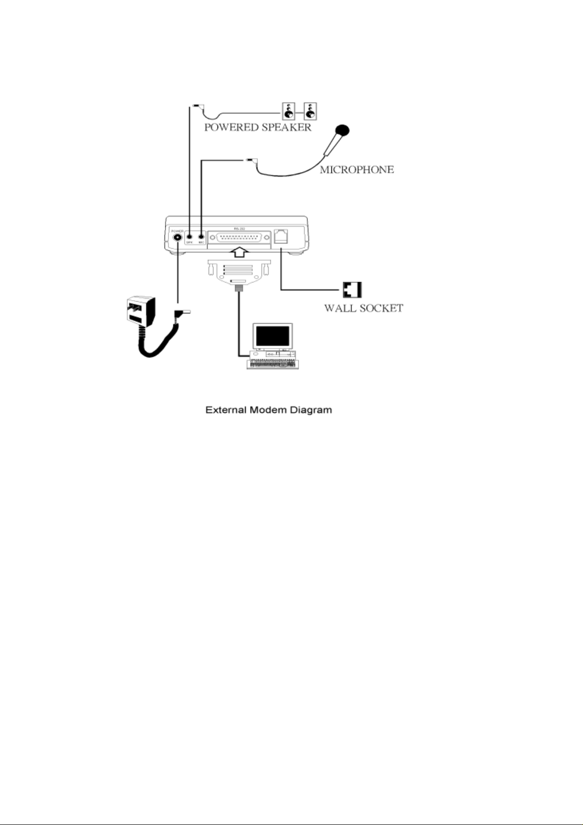
3.3 Connecting To The Telephone Line
Use the following procedure to connect your EZ Modem to the
telephone line:
1. Locate an available RJ-11 modular jack telephone outlet.
2. Take one end of the modular cord supplied with the EZ
Modem and plug it into the LINE modul ar jack on the back o f
the EZ Modem.
3. Plug the other end of the modul ar cor d int o the m odul ar jack
10
Page 11

on the wall outlet, as you would any modular telephone.
3.4 Connecting To Your Telephone Set
Your EZ Modem also conveniently provides a second modular
jack that lets you connect your telephone to the same telephone
line that the EZ M o dem is using. Thi s l ets you manually dial data
calls or make voice call s when you ar e not using y our EZ Modem.
Also if you do not have speakerphone and microphone, handset
of telephone set can function as an input/output device for voice
to verify the connection.
Use the following procedure to connect your telephone to your
EZ Modem:
1. Connect the telephone's modular cord into the PHONE jack
on the back of your EZ Modem.
2. Lift your telephone's handset and listen for a dial tone.
11
Page 12

3.5 Verifying Your Connection
Start a communication program and place the computer into
terminal mode. Refer to your computer manual to find out the
appropriate command to do so.
Then use the following procedure to verify your installation:
Type
1.
AT[Enter]
If your system is operating properly, your EZ
Modem sends an OK response to your screen and
waits for your next command.
Use your communication software to prepare your
2.
computer to dial a call. Then type
ATDx phone number[Enter]
where x is equal to T for touch-tone or P for pulse
dialing.
The
phone number
is your telephone number.
For example, if your EZ Modem is connected to
the telephone line 555-2121 and touch-tone
dialing is supported in your area, type
ATDT 5552121[Enter].
You should hear the busy signal and receive a
3.
BUSY
response because the EZ Modem is
calling itself.
12
Page 13

3.6 Connecting Microphone And Speaker
Y ou coul d either use a handset co nnected to the EZ Mode m,
or connect a microphone an d a spe aker for voice recording
and playback.
NOTE:
Any commercially available microphone is usable.
For the speaker , any 8 ohm speaker rated around 1W att
can be driven directly by the audio output. An amplifier
is required if you need a higher output volume.
1. Connect the microphone to the mini-phone jack marked
.
MIC
2. Connect the speaker to the mini-phone jack marked
.
SPK
13
Page 14
Chapter 4 Software Installation
Configuring External Modem With Windows 98/ME/2000/NT4.0/XP
4.1 Windows 98
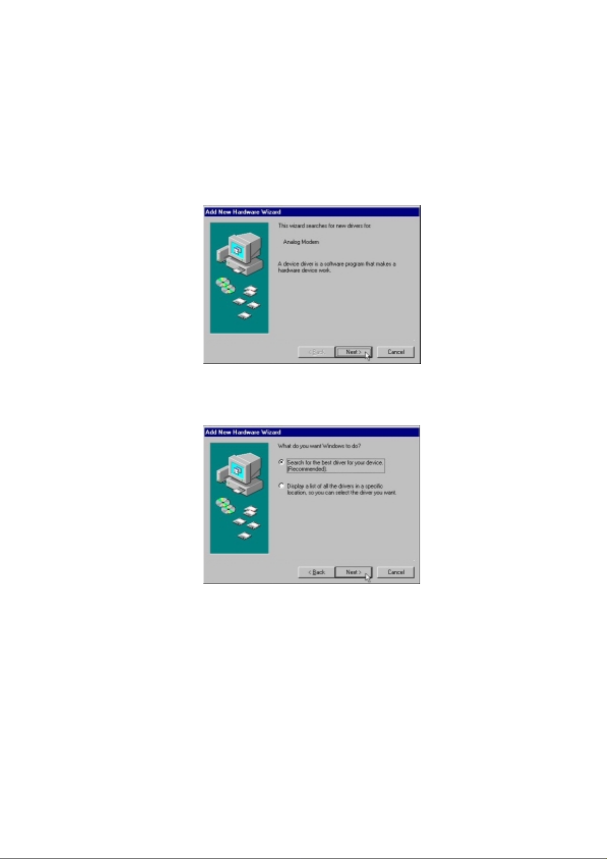
1.
Restart the computer after connecting the modem to PC .When Windows
detects the modem ,the message “This wizard searches for new drives for:”
“
Analog Modem
” is displayed. Click
Next.
2. Select “
click
Search for the best driver for your device, [Recommended].”
.
Next
and
14
Page 15

3. Select
3056EM
“CD-ROM drive”
(F is the letter of CD-ROM drive ) and click
,then select “
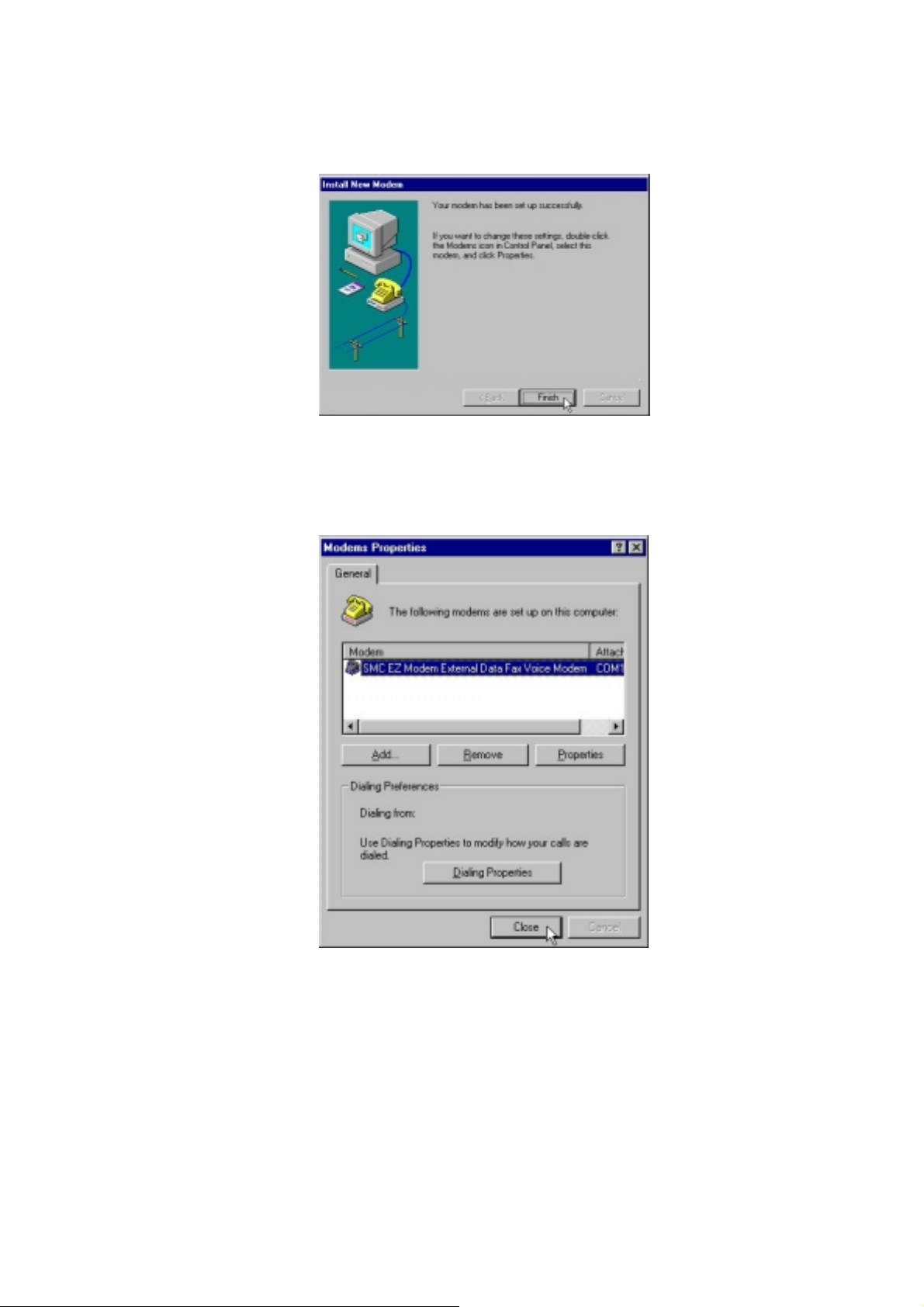
4. Windows will find the driver for
Modem
and click
Next
.
Next
and type
F:\SMC
to continue.
Specify a location:”
SMC EZ Modem External Data Fax Voice
5. Click OK.
15
Page 16

6. Click
.
Finish
to end this installation procedure.
16
Page 17

4.2 Windows ME
1.
The message of
the driver [Advanced]”
2. Select
“Search for the best driver for your device [Recommended]”,
select
Specify a location
drive ) and click
Analog Modem
and click
and type
to continue.
Next
will appear. Select “
.
Next
F:\SMC3056EM
(F is the letter of CD-ROM
Specify the location of
then
17
Page 18

3. Windows will find the driver for a
Modem
4. Click
nd click
Finish
to end this installation procedure.
Next
.
SMC EZ Modem External Data F ax Voice
18
Page 19

4.3 Windows NT
1. Double click “
Modems
2. Check “
Next.
Don’t detect my modem; I will select it from a list
” form
Start
→→→→
Setting
→→→→
Control Panel.
“ and then click
3. Click
Have Disk.
19
Page 20

4. Indicating the path:
F:\SMC3056EM
and then click
5. Select the model of your modem and then click
Next.
OK.
6. Select the COM port that you connect modem to your PC and click
Next.
20
Page 21
7. Windows has finished installing the software. Click
Installation.
8. You can see the modem set up on your PC. Click
Installation.
Close
Finish
to complete
to complete
21
Page 22

4.4 Windows 2000
1. Restart the computer after connecting the modem to PC. When Windows detects
the modem, the wizard will help you to install the new device. Click
begin installation.
to
Next
2. Select”
Next
Search for a suitable driver for my device [recommended]”,
.
and click
22
Page 23

3. Select ”
CD-ROM drives
4. Please type
to continue.
OK
F:\SMC3056EM
” and /or “
Specify a location
”. Then click
Next.
(F is the letter of your CD-ROM driver), then click
5. Click
Next
to continues.
23
Page 24

6. Click
Yes
7. Click
Finish
.
to end procedure.
24
Page 25

4.5 Windows XP
1. Restart the computer after connecting the modem to PC. When Windows detects
the modem, the wizard will help you to install the new device.Select “
form a list or specific location [Advanced ]
Install
”.Then click
Next.
2. Indicating the path:
F:\SMC3056EM
and then click
(F is your CD-ROM)
Next.
25
Page 26

3. Click “
4. Click
Finish.
Continue Anyway
”.
26
Page 27

Chapter 5 Diagnostics
5.1 Windows 98/ME
1. Move your cursor as following sequence
click
Control Panel
2. To test the modem by clicking on the
that the modem is setting, and clicks
. Then double-click on the
More Info…
Start \ Settings \ Control Panel
Modems
Diagnostics
icon.
tab. Select the
.
and
COM port
27
Page 28

3. If your modem is responding to AT commands and functi oning correctly, it
means that your modem is working properly. Click OK to end this procedure.
28
Page 29

5.2 Windows 2000
1. Move your cursor as following sequence
click
Control Panel
icon.
2. Click on the
Modem
and click
Modems
Properties
. Then double-click on the
, then select
SMC EZ Modem External Data Fax Vo ice
.
Start \ Settings \ Control Panel
Phone and Modem Options
and
29
Page 30

3. Click
Diagnostics
. To test the modem by clicking
Query Modem
.
4. If your modem is responding to AT commands and functi oning correctly, it
means that your modem is working properly. Click OK to end this procedure.
30
Page 31

5.3 Windows XP
1. Move your cursor as following sequence
click
Control Panel
icon.
. Then double-click on the
Start \ Settings \ Control Panel
Phone and Modem Options
and
2. Click on the
Voice…
and click
Modems
Properties
, then select
.
SMC EZ Modem External Data Fax
31
Page 32
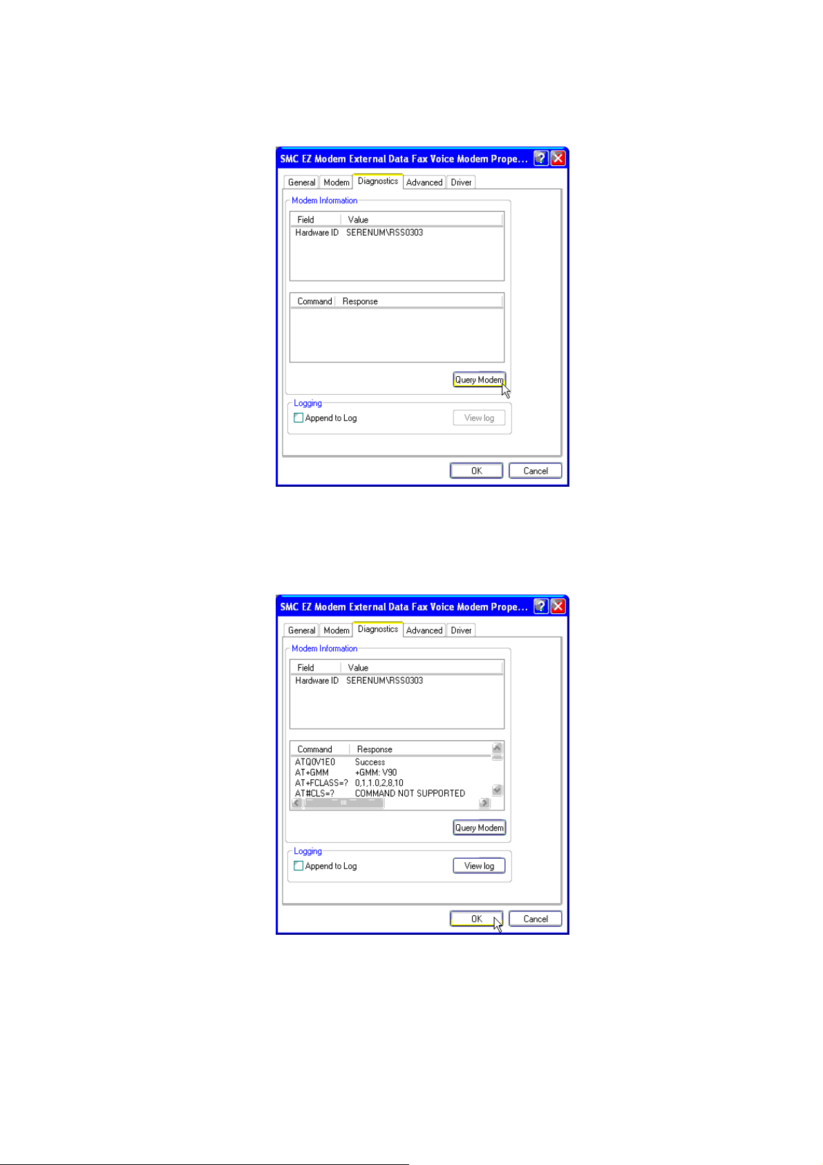
3. Click
Diagnostics
. To test the modem by clicking
Query Modem
4. If your modem is responding to AT commands and functi oning correctly, it
means that your modem is working properly. Click OK to end this procedure
32
Page 33

Chapter 6 Uninstalling Procedures
6.1 Windows 98/ME
1. Please go to
icon.
2. Select
SMC EZ Modem External Data Fax Voice Modem
Start / Settings / Control Panel
and double-click on the
, the click
Modem
Remove
.
33
Page 34

3. Click
Close
.
34
Page 35

6.2 Windows NT
1. Move your cursor as following sequence
click
2. Selec
Control Panel
SMC EZ Modem External Data Fax V oice Modem
. Then double-click on the
Start \ Settings \ Control Panel
Modems
icon.
, then click
Remove
and
.
3. Click
Yes
.
35
Page 36

4. Click
Close.
36
Page 37

6.3 Windows 2000
1. Move your cursor as following sequence
click
Control Panel
2. Click
Next
.
. Then double-click on the
Start \ Settings \ Control Panel
Add/Remove Hardware
and
icon
3. Select
Uninstall/Unplug a device
, then click
Next
.
37
Page 38

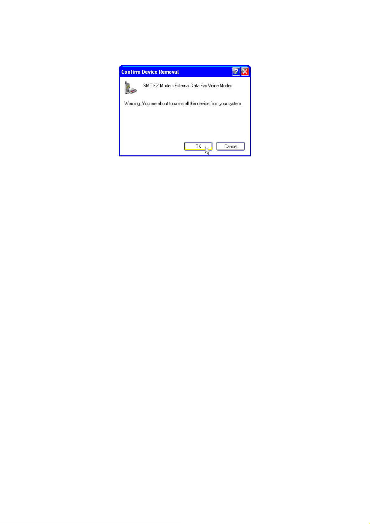
4. Select
5. Select
Uninstall a device
SMC EZ Modem External Data Fax Voice Modem
continue.
and click
Next
to continue.
, then click
Next
to
6. Select
Yes, I want to uninstall this device
, then click
Next
to continue.
38
Page 39

7. Click
Finish
to end this procedure.
39
Page 40

6.4 Windows XP
1. Move your cursor as following sequence
click
Control Panel
. Then double-click on the
Start \ Settings \ Control Panel
System
icon.
and
2. Click
Hardware
tab and select the modem, then click
Device Manager.
40
Page 41

3. Click
Modems
Modem External Data Fax Voice Mo dem
tab and select the modem. Then double-click on the
4. Click
Driver
tab, then click
Uninstall.
SMC EZ
.
41
Page 42
5. Click
OK
to end this procedure.
42
Page 43

Chapter 7 Troubleshooting
Modem will not dial-out
Check your phone cable connected properly into LINE jack.
z
If you use the Tone-dialing on a line, but required the Pulse-dialing method, please
z
change the command T to P i n your dial command line.
Modem will not answer an incoming call
Check your phone cable connected properly into LINE jack.
z
By connect a Telephone to the PHONE jack. The attached telephone will ring if you try
z
calling from another telephone line.
Configured the modem to Auto-answer modem.
z
No connection after modem dial out
Remote modem may be not setting to answer mode, if you aren’t hearing a high-pitch
z
tone when remote modem answering.
Perhaps poor-quality or noise telephone lines try another call.
z
Data error when modem connection
Make sure your software data format is match to remote side (for example: 8,N, 1).
z
Make sure the modem flow control method is matched to communication software.
z
Try another call may be poor quality or noise telephone lines.
z
Fax and voice problems
Be sure the Data Communication is installed and worked properly, otherwise check the
z
mentioned procedure carefully and consult the Fax/Voice manual step by step.
43
Page 44

FOR TECHNICAL SUPPORT, CALL:
From U.S.A. and Canada (24 hours a day, 7 days a week)
(800) SMC-4-YOU; (949) 679-8000; Fax: (949) 679-1481
From Europe (8:00 AM - 5:30 PM UK Time)
44 (0) 118 974 8700; Fax: 44 (0) 118 974 8701
INTERNET
E-mail addresses:
techsupport@smc-asia.com
techsupport@smc.com
european.techsupport@smc-europe.com
World Wide Web:
http://www.smc-asia.com/
http://www.smc.com/
http://www.smc-europe.com/
FOR LITERATURE OR ADVERTISING RESPONSE, CALL:
U.S.A. and Canada: (800) SMC-4-YOU; Fax (949) 679-1481
Spain: 34-93-477-4935; Fax 34-93-477-3774
UK: 44 (0) 118 974 8700; Fax 44 (0) 118 974 8701
France: 33 (0) 41 38 32 32; Fax 33 (0) 41 38 01 58
Italy: 39 02 739 12 33; Fax 39 02 739 14 17
Benelux: 31 33 455 72 88; Fax 31 33 455 73 30
Central Europe: 49 (0) 89 92861-0; Fax 49 (0) 89
92861-230
Switzerland: 41 (0) 1 9409971; Fax 41 (0) 1 9409972
Nordic: 46 (0) 868 70700; Fax 46 (0) 887 62 62
Northern Europe: 44 (0) 118 974 8700; Fax 44 (0) 118 974
8701
Eastern Europe: 34 -93-477-4920; Fax 34 93 477 3774
Sub Saharian Africa: 27-11 314 1133; Fax 27-11 314 9133
North Africa: 34 93 477 4920; Fax 34 93 477 3774
44
Page 45

Russia: 7 (095) 290 29 96; Fax 7 (095) 290 29 96
PRC: 86 21 6485 9922; Fax 86 21 6485 9922
Taiwan: 886 2 8797 8006; Fax 886 2 8797 6288
Asia Pacific: (65) 6238 6556; Fax (65) 6238 6466
Korea: 82 2 553 0860; Fax 82 2 553 7202
Japan: 81 3 5645 5715; Fax 81 3 5645 5715
Australia: 61 2 8875 7887; Fax 61 2 8875 7777
India: 91 22 696 2790; Fax 91 22 696 2794
If you are looking for further contact information, please visit www.smc.com ,
www.smc-europe.com
or www.smc-asia.com.
38 Tesla Model Number: SMC4103P
Irvine, CA 92618
Phone: (949) 679-9000
45
 Loading...