

Page 1
Page 2

Copyright
Information furnished by SMC Networks, Inc. (SMC) is believed to be accurate
and reliable. However, no responsibility is assumed by SMC for its use, nor for
any infringements of patents or other rights of third parties which may result
from its use. No license is granted by implication or otherwise under any patent
or patent rights of SMC. SMC reserves the right to change specifications at any
time without notice.
Copyright © 2003 by
SMC Networks, Inc.
38 Tesla
Irvine, California 92618
All rights reserved.
Trademarks
SMC® is a registered trademark; and EZ-Stream, EZ Connect, Barricade and EZ
Hub are trademarks of SMC Networks, Inc. Other product and company names
are trademarks or registered trademarks of their respective holders.
Page 3

Compliances
FCC - Class B
The Federal Communication Commission Radio Frequency Interference
Statement includes the following paragraph:
The equipment has been tested and found to comply with the limits for a Class B
Digital Device, pursuant to part 15 of the FCC Rules. These limits are designed to
provide reasonable protection against harmful interference in a residential
installation. This equipment generates, uses and can radiate radio frequency
energy and, if not installed and used in accordance with the instruction, may
cause harmful interference to radio communication. However, there is no
guarantee that interference will not occur in a particular installation. If this
equipment does cause harmful interference to radio or television reception,
which can be determined by turning the equipment off and on, the user is
encouraged to try to overcome the interference by one or more of the following
measures:
--Reorient or relocate the receiving antenna.
--Increase the separation between the equipment and receiver.
--Connect the equipment into an outlet on a circuit different from that to which
the receiver is connected.
--Consult the dealer or an experienced radio/TV technician for help.
The equipment is for home or office use.
FCC ID INFORMATION
The product contains an approved FCC module ID: “QDWWN360G”.
CAUTION STATEMENT:
FCC Radiation Exposure Statement
FCC RF Radiation Exposure Statement: This equipment complies with FCC RF
radiation exposure limits set forth for an uncontrolled environment. This
equipment should be installed and operated with a minimum distance of 20cm
between the antenna and your body and must not be co-located or operating in
conjunction with any other antenna or transmitter.
Caution: Changes or modifications not expressly approved by the party
responsible for compliance could void the user's authority to operate the
equipment.
Industry Canada – Class B
This digital apparatus does not exceed the Class B limits for radio noise
emissions from digital apparatus as set out in the interference-causing
equipment standard entitled "Digital Apparatus", ICES-003 of Industry Canada.
Page 4

Cet appareil numerique respecte les limites de bruits radioelectriques applicables
aux appareils numeriques de Classe B prescrites dans la norme sur le material
brouilleur: "Appareils Numeriques," NMB-003 edictee par l'Industrie.
Low Power License-Exempt Radio communication Devices (RSS-210)
1. Warning Note: operation is subject to the following two conditions: (1) this
device may not cause interference, and (2) this device must accept any
interference, including interference that may cause undesired operation of the
device.
2. Operation in 2.4GHz band: To prevent radio interference to the licensed
service, this device is intended to be operated indoors and away from windows
to provide maximum shielding. Equipment (or its transmit antenna) that is
installed outdoors
is subject to licensing.
Exposure of Humans to RF Fields for Mobile Radios Equipment
(RSS-102)
1. Mobile radios that are not body worn (e.g. mounted on vehicles or placed on
desks, shelves, etc.) and operated such that humans are normally separated
from their radiating element by at least 20cm are not subject to SAR tests, but
must have an RF evaluation
by the certification applicant, based on the calculated or measured field strength
value. SAR evaluation can be used if so desired in lieu of a RF evaluation of field
strength limits.
2. Exposures produced by such radios shall not exceed the exposure limits
specified in Health Canada's Safety Code 6. Health Canada’ s address is:
775 Brookfield Road, Ottawa, Ontario
Canada K1A 1C1; Tel: (613) 954 -6699 / Fax:(613) 941-1734 ;
e-mail: alice_mackinnon@hc-sc.gc.ca.
EC Conformance Declaration - Class B
SMC contact for these products in Europe is:
SMC Networks Europe,
Edificio Conata II,
Calle Fructuós Gelabert 6-8, Planta 2,
08970 - Sant Joan Despí,
Barcelona, Spain.
This RF product complies with all the requirements of the Directive 1999/5/EC of
the European parliament and the council of 9 March 1999 on radio equipment
and telecommunication terminal Equipment and the mutual recognition of their
conformity(R&TTE).
Page 5

The R&TTE Directive repeals and replaces in the directive 98/13/EEC. As of April
8, 2000.
Important Safety Notices
• Unplug this product from the AC power before cleaning. Do not use liquid
cleaners or aerosol cleaners. Use a dry cloth for cleaning.
• Route the power supply cords so that they are not likely to be walked on
or pinched by items placed upon or against them. Pay particular attention
to cords at plugs, convenience receptacles, and the point where they exit
from the product.
• Situate the product away from heat sources such as radiators, heat
registers, stoves, and other products that produce heat.
• To prevent fire or shock hazard, do not expose this unit to rain or
moisture. Do not allow water or any foreign objects to enter the interior.
This may cause a fire or electric shock. In the event that water or other
foreign objects get into the product, immediately unplug the AC adapter
from the electrical outlet and contact Customer Service for inspection
and/or repair/replacement options.
• Do not take apart the equipment. This may cause fire, electric shock or
other injuries.
• Do not overload wall outlets and extension cords as this can result in a fire
or electric shock.
• This product is for use with the AC adapter that comes with it. Use with
any other AC power is strongly discouraged as it may cause fire, electric
shock, or damage to the equipment.
Page 6

1 | System Requirements
• A web browser, such as Microsoft Internet Explorer 5.5 or above installed
on one PC at your site for configuring the Wireless Ethernet Bridge
• CD-ROM drive
• An AC power outlet to supply power to the Wireless Ethernet Bridge
• Wired or Wireless Network Adapter
• An available RJ-45 (UTP) port on an Ethernet hub or switch
• TCP/IP network protocol installed on each PC that needs to access the
Internet.
2 | Equipment Checklist
After unpacking the EZ Connect™ g 2.4GHz 54 Mbps Wireless Ethernet Bridge,
check the contents of the box to be sure you have received the following
components:
• 1 SMC2870W 2.4GHz 54 Mbps Wireless Ethernet Bridge
• 1 EZ Installation Wizard and Documentation CD
• 1 Quick Installation Guide
Immediately inform your dealer in the event of any incorrect, missing or
damaged parts. If possible, please retain the carton and original packing
materials in case there is a need to return the product.
Please register this product and upgrade the product warranty at SMC’s Web
site: http://www.smc.com
Page 7
3 | Hardware Description
The EZ Connect™ g Wireless Ethernet Bridge supports high speed
communication up to 54 Mbps. It incorporates support for PRISM Nitro which
provides enhanced throughput and range. This device is fully compliant with 2.4
GHz DSSS and OFDM CSMA/CA wireless networking as defined in IEEE 802.11b
and 802.11g. It can be connected via an RJ-45 connection to devices such as
Nintendo GameCube, Microsoft Xbox, Sony PlayStation II, and Ethernet ready
embedded devices. It can also function as an IEEE 802.11g Access Point, giving
you the capability of creating a new 802.11g wireless network. In addition, this
product supports Wireless Distribution System (WDS) for repeater functionality to
extend the range of your wireless network.
Page 8
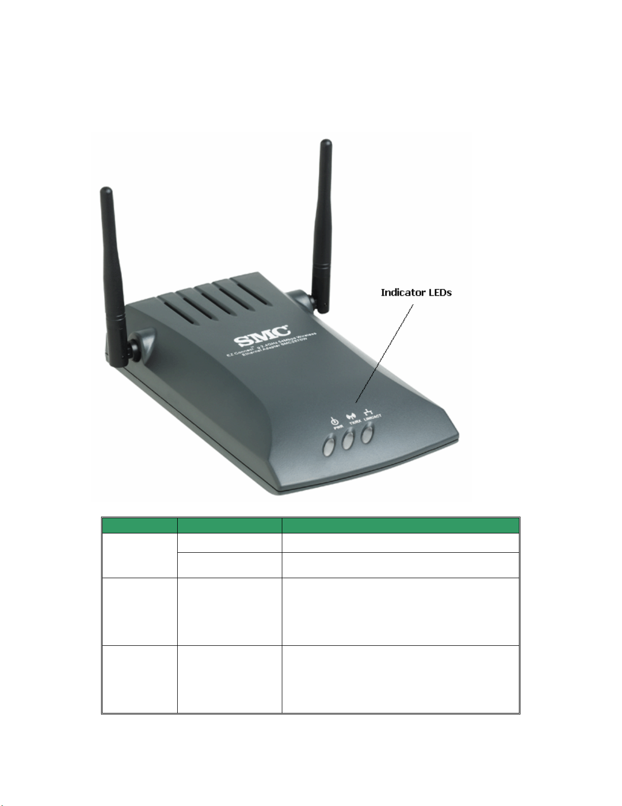
The EZ Connect™ g 54 Mbps Wireless Ethernet Bridge has three types of LED
indicators. Please check the following picture – the front view of the Bridge and
the table below, which displays the current state the specific LED signifies.
LED Status Function
Power
(PWR)
Wireless
LAN
(TX/RX)
LAN
(LINK/ACT)
On (Green) Power on.
Off No power.
Blinking (Green)
On (Green)
Off
Blinking (Green)
On (Green)
Off
Blinking: Wireless LAN connection is
transmitting.
On: Wireless LAN connection is active.
Off: Wireless LAN connection is not active.
Blinking: Wired LAN connection is
transmitting.
On: Wired LAN connection is active.
Off: Wired LAN connection is not active.
Page 9

DEFAULT SETTINGS
SSID
Wireless Adapter
Name
IP Address
Subnet Mask
Gateway
Mode
SMC
SMC2870W
192.168.2.25
255.255.255.0
192.168.2.1
Wireless Bridge
4 | Applications
SMC’s EZ Connect 2.4GHz 54 Mbps Wireless Ethernet Bridge (SMC2870W) can
function as:
• an Ethernet to Wireless Bridge, providing a wireless connection via an RJ-45
connection to devices such as Microsoft Xbox and Ethernet ready embedded
devices
• a standard IEEE 802.11g access point
• a wireless repeater, allowing you to effectively extend the coverage of another
SMC2870W that is configured to operate in Access Point mode
This solution offers fast, reliable wireless connectivity with considerable cost
savings over wired LANs (eliminates long-term maintenance overhead for
cabling). Just install enough wireless access points to cover your network area,
plug wireless cards into your notebooks or install wireless adapters into your
desktops, and start networking.
Use this device in conjunction with SMC’s EZ Connect™ Wireless Cards to create
an instant network that integrates seamlessly with Ethernet LANs. Moreover,
moving or expanding your network is as easy as moving or installing additional
access points – no wires!
EZ Connect wireless products offer a fast, reliable, cost-effective solution for
wireless Ethernet client access to the network in applications such as:
• Video Game Systems
Provides wireless Internet access for users of video game systems such as
Nintendo GameCube, Microsoft Xbox and Sony PlayStation II
• Remote access to corporate network information
E-mail, file transfer, and terminal emulation
Page 10

• Difficult-to-wire environments
Historical or old buildings, asbestos installations, and open areas where wiring is
difficult to employ
• Frequently changing environments
Retailers, manufacturers, and banks which frequently rearrange the workplace or
change locations
• Temporary LANs for special projects or peak periods
Trade shows, exhibitions, and construction sites that need a temporary setup.
Retailers, airline, and shipping companies that need additional workstations for
peak periods. Auditors who require workgroups at customer sites
• Access to databases for mobile workers
Doctors, nurses, retailers, or white-collar workers who need access to databases
while being mobile in a hospital, retail store, in an office, or on a campus
• SOHO users
SOHO (Small Office and Home Office) users who need easy and quick installation
of a small computer network
Page 11

5 | Understanding Wireless Security
Anyone within range of your wireless network is a potential security risk. Without
wireless security options configured on your network, a person outside of your
physical location, but within your wireless range may be able to access the
network and any data that is being transmitted over it. SMC Networks’ wireless
devices support the wireless security standard called Wired Equivalent Privacy
(WEP) to prevent unauthorized users from accessing your network over a
wireless connection. This security feature uses a secure network key, called a
WEP key. The WEP key encrypts wireless data so that it is only readable by other
computers that have the matching WEP key. The WEP key is stored on each
wireless device, so that data can be encrypted and decrypted as it is transmitted
over the network.
While the Institute of Electrical & Electronics Engineers (IEEE) 802.11i standard
is being finalized, an interim solution called Wi-Fi Protected Access (WPA) has
been introduced. The EZ Connect™ g Wireless Ethernet Bridge is the first device
of its kind to support this new wireless security specification. WPA defines a set
of interoperable security enhancements that greatly improve upon the level of
data encryption and authentication or access control for existing and future
wireless LAN systems. WPA includes Extensible Authentication Protocol (EAP),
Temporal Key Integrity Protocol (TKIP) and 802.1X for authentication and
dynamic key exchange. In the WPA-enabled network, the client first associates
with the Access Point. The Access Point does not allow network access until the
user can be successfully authenticated. If the client shows the correct credentials
to the Remote Authentication Dial-In User Service (RADIUS) server, the client is
allowed to join the network. If not, the client stays blocked from joining the LAN.
Once the client joins the network, the authentication server distributes a TKIP
encryption key to both the client and the Access Point. The client can then begin
communicating on the network and maintain the connection, encrypting data
back and forth with the Access Point. Note that for environments without a
Remote Authentication Dial-In User Service (RADIUS) infrastructure, WPA
supports the use of a pre-shared key (PSK). WPA-PSK specifies that encryption
keys be dynamically changed (called rekeying) and authenticated between
devices after a specified period of time, or after a specified number of packets
has been transferred.
If you are transferring private information over this wireless connection, it is
recommended to enable WEP or WPA for your EZ Connect™ g Wireless Ethernet
Bridge.
Page 12

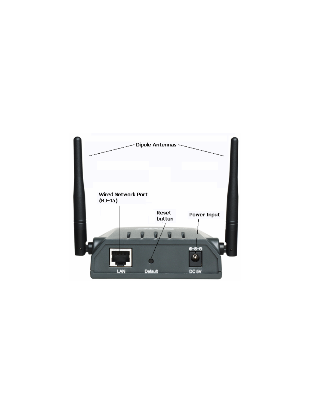
6 | Hardware Installation
1. Select the Site – Choose a location for your Wireless Ethernet Bridge. Usually,
the best location is at the center of your wireless coverage area, if possible
within line-of-sight of all wireless devices.
2. Place the Wireless Ethernet Bridge in a position that gives it maximum
coverage. Normally, the higher you place the antenna, the better the
performance.
3. Position the antennas in the desired positions. For more effective coverage,
position the antennas along different axes. For example, try positioning the
antennas around 45 to 90 degrees apart. (The antennas emit signals along the
toroidal plane – and thus provide more effective coverage when positioned along
different axes.)
4. If used in Wireless Bridge mode, connect the Ethernet cable to the RJ-45
socket of the device will communicate wirelessly with an access point.
5. If used in Access Point mode, connect the Ethernet cable – The SMC2870W
can be wired to an Ethernet network through an Ethernet device such as a hub
or a switch using category 3, 4, or 5 UTP Ethernet cable and an RJ-45 connector.
6. Connect the power cable – Connect the power adapter cable to the 5 VDC
power socket on the rear panel. Warning: Use only the power adapter supplied
with the SMC2870W.
7. Check the LED’s on the front of the unit to make sure the adapter is turned on
properly and the status is okay.
Page 13
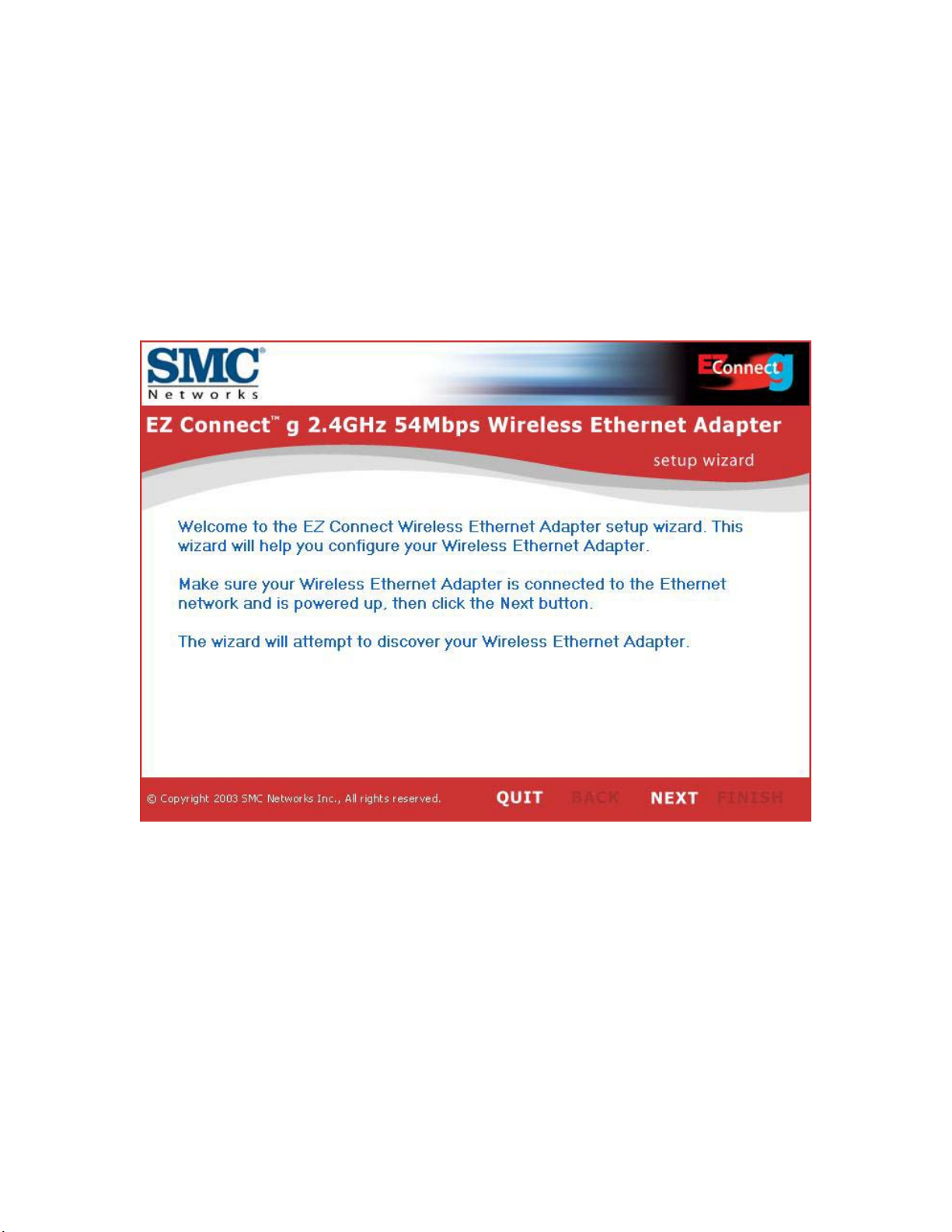
7 | Using the EZ Installation Wizard
The installation method makes the process as simple and Plug-and-Play as
possible. Please be sure that you have successfully completed the steps shown in
Section 6 before proceeding.
1. Insert the EZ Installation Wizard and Documentation CD.
2. Click the [NEXT] button to continue.
Page 14
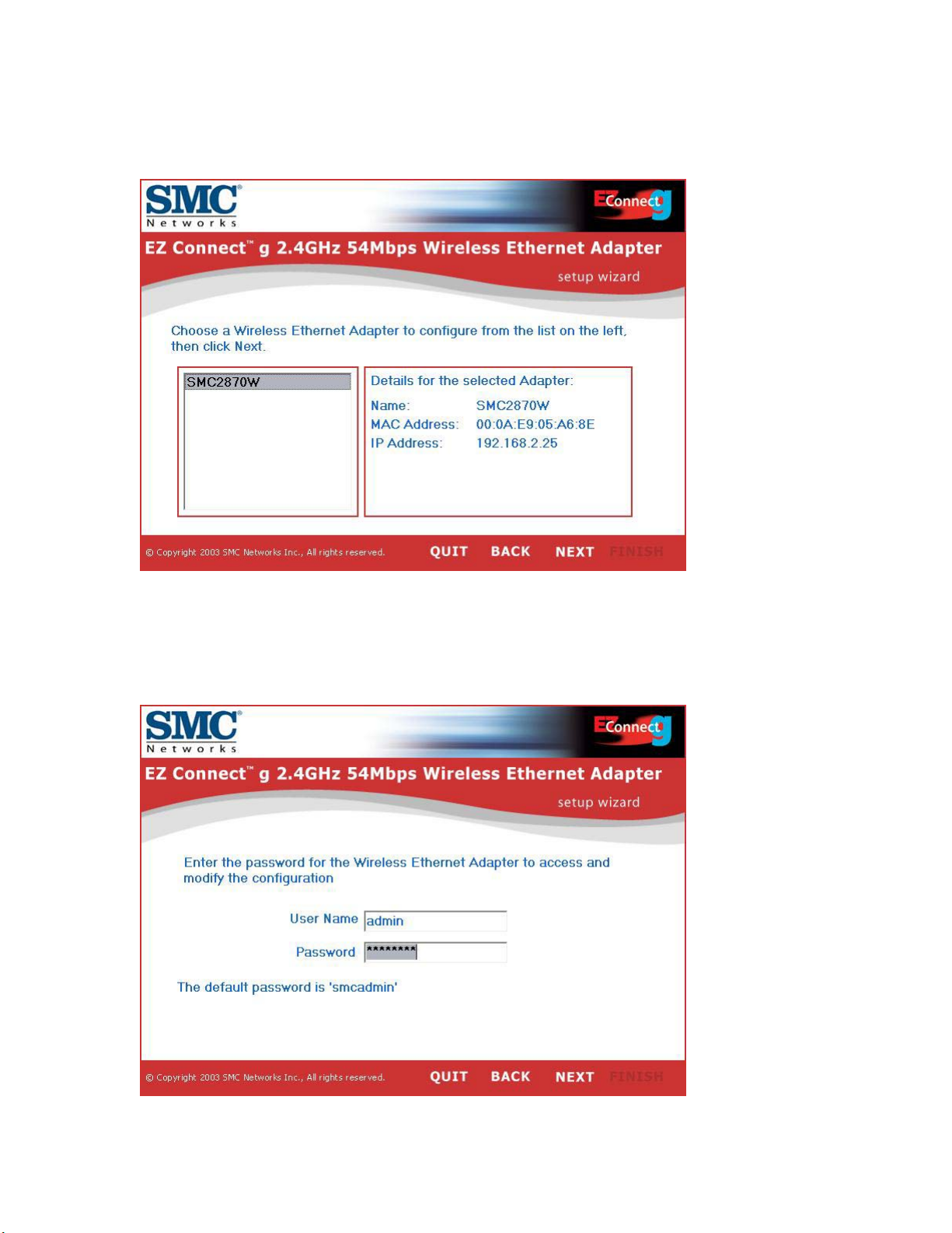
3. The wizard will scan for available SMC2870W’s and then list them on the left
column. Click [NEXT] to continue.
4. You will be asked to enter the password to modify the current configuration
settings. By default, the username is “admin” and the password is “smcadmin”.
Please enter this information and press [NEXT].
Page 15
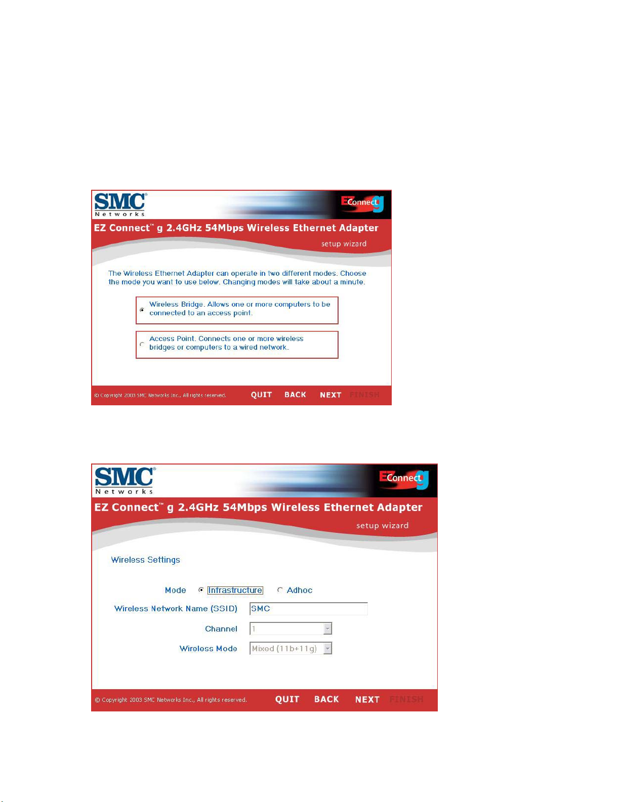
5. You will then be given the option to enable either “Wireless Bridge” or “Access
Point” mode. If you are trying to create a new 802.11g network for your wireless
clients to connect up to, please select “Access Point” and click [NEXT]. If you are
trying to give an Ethernet-equipped device wireless connectivity, please select
“Wireless Bridge” and click [NEXT]. If you selected “Wireless Bridge”, please go
to Step 6. If you selected “Access Point”, go to Step 10.
6. Wireless Bridge configuration: If you are connecting to an existing
wireless network, select “Infrastructure” and enter the SSID of your network.
Page 16
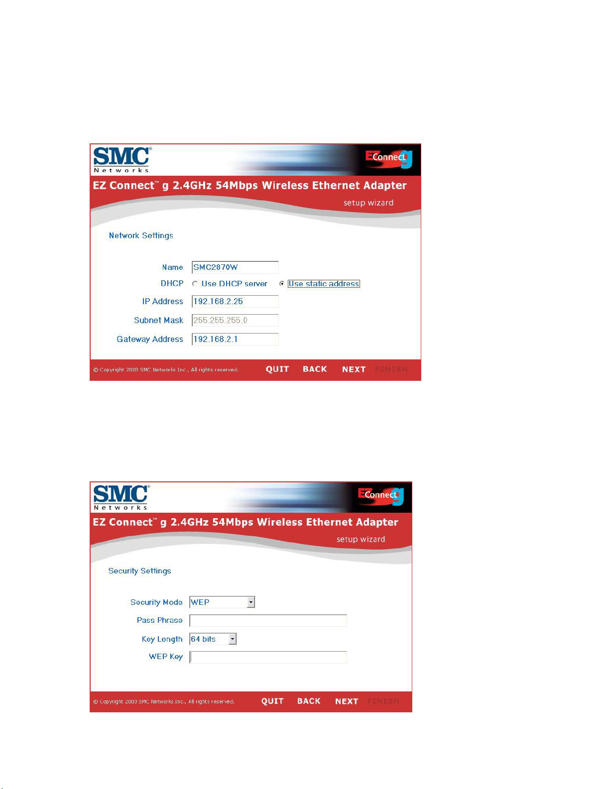
7. Now you will be asked to configure the Network Settings. If you are
connecting to a network with a DHCP server, select “Use DHCP server” and click
[NEXT]. If you do not have a DHCP server on your network, input a static IP
address and click [NEXT].
8. If you have enabled Wired Equivalent Privacy (WEP) or Wi-Fi Protected Access
(WPA) on your wireless network, please enter the private security key settings
now. Select the drop down menus of “Security Mode” to choose between WEP
and WPA. Select the drop down menus of “Key Length” to choose between 64 or
128-bit encryption.
Page 17
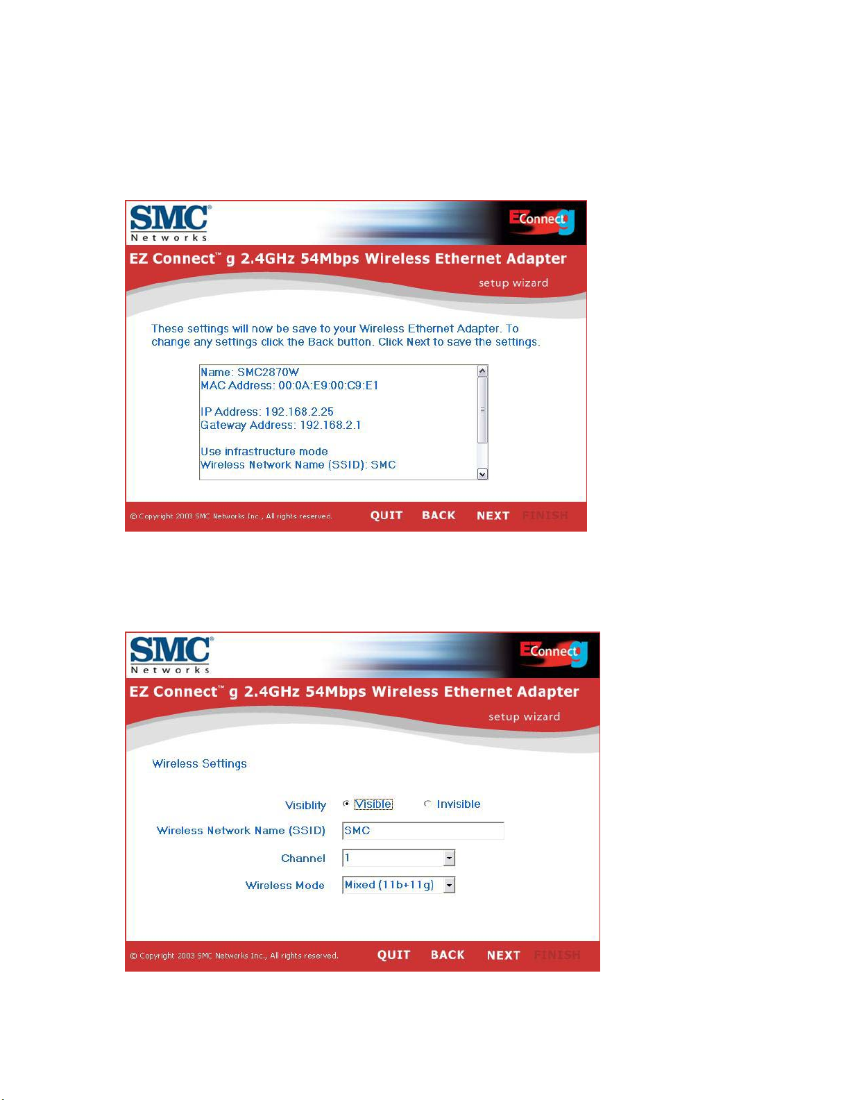
9. Finally, please verify all the settings you have entered. If any configuration
changes still need to be made, please click [BACK] and make them now.
Otherwise, click [NEXT] to make the settings take effect. This will take a few
seconds. Please go to Step 14.
10. Access Point configuration: To disable SSID broadcast, select “Invisible”.
Please enter your desired SSID, Channel and Wireless Mode settings and click
[NEXT] to continue.
Page 18

11. Now you will be asked to configure the Network Settings. If you are
connecting to a network with a DHCP server, select “Use DHCP server” and click
[NEXT]. If you do not have a DHCP server on your network, input a static IP
address and click [NEXT].
12. If you would like to enable Wired Equivalent Privacy (WEP) or Wi-Fi
Protected Access (WPA) on your wireless network, please enter the private
security key settings now. Select the drop down menus of “Security Mode” to
choose between WEP and WPA. Select the drop down menus of “Key Length” to
choose between 64 or 128-bit encryption.
Page 19

13. Finally, please verify all the settings you have entered. If any configuration
changes still need to be made, please click [BACK] and make them now.
Otherwise, click [NEXT] to make the settings take effect.
14. You have now completed the configuration. You can now begin to use your
EZ Connect ™ g Wireless Ethernet Bridge.
Page 20

8 | Configuring Your Computer
Using IPCONFIG
1) Click the “Start” button, click “Run” and type “command”.
2) Press “OK” and a black command prompt will appear.
3) Type “ipconfig” and press enter
4) Verify that your IP Address is 192.168.2.xxx. If so, you can now use the
web interface of the SMC2870W to configure additional advanced
settings. If your IP Address is completely different, please go to the
“Configure Your IP Address” section below.
Configuring Your IP Address
Windows 98/ME
NOTE: Some Windows 9x/ME systems will request that you insert your Windows
CD in order to complete the following configuration. Please have this CD ready.
1) Click the "Start" button, choose "Settings", and then click "Control Panel".
2) Double-click the "Network" icon.
Page 21

3) Select the TCP/IP that is bound to the network adapter that you are
currently using to configure your SMC2870W. Click "Properties".
4) Select the Specify an IP option and insert 192.168.2.x (where x is 2 ~ 24,
26 ~ 254). Then insert 255.255.255.0 for the subnet mask.
5) Press OK and reboot the machine when prompted to do so.
Page 22

Windows 2000
1) Right-click the "Network Places" icon on your desktop and click
"Properties".
2) Right-click your Local Area Connection and click "Properties".
Page 23

3) Click “Internet Protocol TCP/IP” and click “Properties”. Select the "Use the
following IP Address" option and insert 192.168.2.x (where x is 2 ~ 24, 25
~254). If requested to enter a gateway and DNS, you can enter
192.168.2.1.
4) Click "OK" and click "Close" to continue and save the changes.
Windows XP
1) Right-click the "Network Places" icon on your desktop and click
"Properties".
Page 24

2) Right-click your "Local Area Connection" and click "Properties".
3) Click “Internet Protocol TCP/IP” and click “Properties”. Select the "Use the
following IP Address" option and insert 192.168.2.x (where x is 2 ~ 24, 26
~ 254) for the IP address. If requested to enter a gateway and DNS, you
can type in 192.168.2.1.
Page 25

4) Click "OK" and click "Close" to continue and save the changes.
Page 26

9 | Advanced Web Configuration (Wireless Bridge mode)
Use the web management interface to define advanced system parameters,
manage and control the Wireless Ethernet Bridge and its ports, or monitor
network conditions. (Note: You MUST press [Save] and then [Reboot] for
changes to take effect.)
Browser Configuration
Confirm your browser is configured for a direct connection to the Internet using
the Ethernet cable that is installed in the computer. This is configured through
the options/preference section of your browser.
You will also need to verify that the HTTP Proxy feature of your web browser is
disabled. This is so that your web browser will be able to view the SMC2870W
configuration pages. The following steps are for Internet Explorer. Determine
which browser you use and follow the appropriate steps.
Internet Explorer in Windows
1. Open Internet Explorer. Click Tools, and then select Internet Options.
2. In the Internet Options window, click the Connections tab.
3. Click the LAN Settings button.
4. Clear all the check boxes and click OK to save these LAN settings changes.
5. Click OK again to close the Internet Options window.
Internet Explorer in Macintosh
1. Open Internet Explorer. Click Explorer/Preferences.
2. In the Internet/Explorer/Preferences window, under Network, select Proxies.
3. Uncheck all check boxes and click OK.
To access the SMC2870W’s web management interface, enter the Wireless
Ethernet Bridge IP address in your web browser as follows: http://192.168.2.25
Then enter the username and password and then click LOGIN.
Default username: admin
Default password: smcadmin
Page 27

After logging into the SMC2870W, all the System Information will be displayed.
You can proceed to another configuration page using the navigational menu on
the left.
Note: If you know the SSID or BSSID of your desired network, you can
automatically connect to it by moving your mouse over the appropriate BSSID of
the network and then click the link.
Page 28

Go to Wireless | Basic Settings to change the Wireless Bridge mode from
Infrastructure to Adhoc, or you can also change the SSID, Channel, Transmission
Rate and Wireless Mode.
Note that when configured as a Wireless Bridge, changing the channel of the
SMC2870W has no effect because it must connect to the network using the same
channel as your Access Point. If you wish to use a different channel, you must
change the channel in your Access Point’s configuration.
Page 29

Go to Wireless | Advanced Settings in order to change the Fragmentation and
RTS thresholds. (Note: It is recommended to leave these values at their default
settings.)
RTS Threshold: Set the RTS (Request to Send) frame length. You may configure
the access point to initiate an RTS frame. If the packet size is smaller than the
preset RTS threshold size, the RTS/CTS mechanism will NOT be enabled.
The access point sends Request to Send (RTS) frames to a particular receiving
station to negotiate the sending of a data frame. After receiving an RTS, the
station sends a CTS (Clear to Send) frame to acknowledge the right of the
sending station to send data frames. The access points contending for the
medium may not be aware of each other. The RTS/CTS mechanism can solve
this “Hidden Node Problem.”
Fragmentation Threshold: If the packet size is smaller than the preset Fragment
size, the packet will not be segmented. Fragmentation of the PDUs (Package
Data Unit) can increase the reliability of transmissions because it increases the
probability of a successful transmission due to smaller frame size. If there is
significant interference present, or collisions due to high network utilization, try
setting the fragment size to send smaller fragments. This will enable the
retransmission of smaller frames much faster. However, it is more efficient to set
the fragment size larger if very little or no interference is present because it
requires overhead to send multiple frames.
Page 30

Go to Wireless | Security to configure wireless security. If you have Wi-Fi
Protected Access (WPA) security enabled on your wireless LAN, please click the
[WPA enabled] checkbox and enter your pre-shared key (PSK):
Page 31

If you have Wired Equivalent Privacy (WEP) security enabled on your wireless
LAN, please click the [Enable WEP] checkbox. Then enter your desired key
length and default WEP key. You can use the Passphrase function to
automatically generate a WEP key or you can enter the full 10-digit (64-bit WEP)
or 26-digit (128-bit WEP) manually in the “WEP key” field. Select your
“Authentication” method and press [Save].
Note: A passphrase can contain up to 32 alphanumeric characters.
When setting up WEP without using the Passphrase function, only Hexadecimal
characters (range: 0~9 and A~F) can be used. When encryption is set to 64-bit,
a maximum of 10 Hex characters can be entered in the Key field. When
encryption is set to 128-bit, a maximum of 26 Hex characters can be used.
Page 32

Go to System | Admin Settings to change additional advanced settings. (Note: If
you are not sure how to use a particular setting or what it means, please review
the Terminology section before continuing. Any erroneous changes made here
may cause unwanted results.)
In the Device Name section, you can change the name of a particular
SMC2870W device. This is very useful if you have more than one SMC2870W on
your network.
In the IP Settings section, you can configure the unit with a static IP or set it up
to use Dynamic Host Configuration Protocol (DHCP). Note: If you want to use
DHCP, you must first make sure that you have a DHCP Server on your network
ready to distribute additional IP Addresses.
Page 33

In the Security section, change the username and/or password used to log into
the SMC2870W. It is a good idea to write down your username and password if
you decide to change it. If you forget this information in the future, you will need
to reset the SMC2870W to defaults.
In the Commands section, you can reboot your SMC2870W or reset it to
defaults.
As we add functionality and future enhancements are made, firmware updates
will be posted to SMC’s website. After downloading the firmware, you need to
update the SMC2870W via the web interface under this Upgrade Firmware
section. Simply click the [Browse] button to locate and select the new firmware
and then press [Upload].
Page 34

10 | Advanced Web Configuration (Access Point mode)
Use the web management interface to define advanced system parameters,
manage and control the Wireless Ethernet Bridge and its ports, or monitor
network conditions.
Browser Configuration
Confirm your browser is configured for a direct connection to the Internet using
the Ethernet cable that is installed in the computer. This is configured through
the options/preference section of your browser.
You will also need to verify that the HTTP Proxy feature of your web browser is
disabled. This is so that your web browser will be able to view the SMC2870W
configuration pages. The following steps are for Internet Explorer. Determine
which browser you use and follow the appropriate steps.
Internet Explorer in Windows
1. Open Internet Explorer. Click Tools, and then select Internet Options.
2. In the Internet Options window, click the Connections tab.
3. Click the LAN Settings button.
4. Clear all the check boxes and click OK to save these LAN settings changes.
5. Click OK again to close the Internet Options window.
Internet Explorer in Macintosh
1. Open Internet Explorer. Click Explorer/Preferences.
2. In the Internet/Explorer/Preferences window, under Network, select Proxies.
3. Uncheck all check boxes and click OK.
To access the SMC2870W’s web management interface, enter the Wireless
Ethernet Bridge IP address in your web browser as follows: http://192.168.2.25
Then enter the username and password and then click LOGIN.
Default username: admin
Default password: smcadmin
Page 35

After logging into the SMC2870W, all the System Information will be displayed.
You can proceed to another configuration page using the navigational menu on
the left.
Go to the Status | Associations page to view all the wireless clients that are
connected to your SMC2870W. The MAC Addresses of the clients will be shown.
This is helpful if you plan to configure MAC Address Filtering in the future. You
can simply highlight the appropriate MAC Address, copy and paste it in the
section called Wireless | Access List.
Page 36

Go to Wireless | Basic Settings to change parameters such as the SSID, channel,
and transmit rate. You can also change the “Visibility Status”. Selecting [Visible]
enables SSID broadcast whereas selecting [Invisible] disables the SSID
broadcast. The “Wireless Mode” dictates what type of wireless client is allowed to
associate to the SMC2870W. The supported modes are Mixed (11b+11g), Long
Range Mixed (11b+11g), 11g Only, and 11b Only.
Page 37

Go to Wireless | Access List to enter specific MAC Addresses that are allowed to
connect to the SMC2870W. This function gives you added security without the
overhead and increased processing that WEP or WPA may require.
Go to Wireless | Repeater to make use of the repeating functionality to extend
the wireless range of your network. (Note: You need at least two SMC2870W
units in order to successfully enable repeating on your wireless LAN)
This function makes use of Wireless Distribution System (WDS) technology. You
can specify up to six WDS links, where each link is defined by the MAC addresses
of the other repeater capable SMC2870W. (Note: The repeater function must be
enabled on both ends in order to function properly.)
Page 38

Go to Wireless | Advanced Settings in order to change the Fragmentation and
RTS thresholds. (Note: It is recommended to leave these values at their default
settings.)
RTS Threshold: Set the RTS (Request to Send) frame length. You may configure
the access point to initiate an RTS frame. If the packet size is smaller than the
preset RTS threshold size, the RTS/CTS mechanism will NOT be enabled.
The access point sends Request to Send (RTS) frames to a particular receiving
station to negotiate the sending of a data frame. After receiving an RTS, the
station sends a CTS (Clear to Send) frame to acknowledge the right of the
sending station to send data frames. The access points contending for the
medium may not be aware of each other. The RTS/CTS mechanism can solve
this “Hidden Node Problem.”
Fragmentation Threshold: If the packet size is smaller than the preset Fragment
size, the packet will not be segmented. Fragmentation of the PDUs (Package
Data Unit) can increase the reliability of transmissions because it increases the
probability of a successful transmission due to smaller frame size. If there is
significant interference present, or collisions due to high network utilization, try
setting the fragment size to send smaller fragments. This will enable the
retransmission of smaller frames much faster. However, it is more efficient to set
the fragment size larger if very little or no interference is present because it
requires overhead to send multiple frames.
Page 39

Beacon Interval: Set the interval value of beacon between synchronized frames.
These synchronous frames also contain indication of frames that need to
transmit to the power-saved stations.
DTIM: Set the Delivery Traffic Indication Message (DTIM) interval value. The
DTIM indicates how often the MAC layer forwards multicast traffic. This
parameter is necessary to accommodate stations using Power Save mode. In
order to maximize the utilization of channels, broadcast data is not transmitted
every beacon for stations in Power Save mode. These power-saved stations must
wake up to receive broadcast data at the DTIM interval. The DTIM is the interval
between two synchronous frames with broadcast information. If you set the
value to 2, the access point will save all multicast frames for the BSS and
forward them after every second beacon. Having smaller DTIM intervals delivers
multicast frames in a more timely manner, causing stations in Power Save mode
to wake up more often and drain power faster. Having higher DTIM values,
though, delays the transmission of multicast frames.
Go to Wireless | Security to configure wireless security. Please click the [WPA
enabled] checkbox and enter your desired pre-shared key (PSK) if you want to
enable Wi-Fi Protected Access (WPA) security on your wireless LAN. You can also
set the “WPA Group Key Update Interval” value. This specifies how often the
wireless encryption keys are dynamically changed and clients re-authenticate.
Page 40

If you have a RADIUS server on your network, you can configure the SMC2870W
to use it for the purpose of authenticating clients to your wireless LAN. Simply
click the [802.1x enabled] checkbox and enter your settings:
Page 41

Please click the [Enable WEP] checkbox if you want to enable Wired Equivalent
Privacy (WEP) security on your wireless LAN. Then enter your desired key length
and default WEP key. You can use the Passphrase function to automatically
generate a WEP key or you can enter the full 10-digit (64-bit WEP) or 26-digit
(128-bit WEP) manually in the “WEP key” field. Select your “Authentication”
method and press [Save].
Note: A passphrase can contain up to 32 alphanumeric characters.
When setting up WEP without using the Passphrase function, only Hexadecimal
characters (range: 0~9 and A~F) can be used. When encryption is set to 64-bit,
a maximum of 10 Hex characters can be entered in the Key field. When
encryption is set to 128-bit, a maximum of 26 Hex characters can be used.
Page 42

Go to System | IP Settings to change additional advanced settings. (Note: If you
are not sure how to use a particular setting or what it means, please review the
Terminology section before continuing. Any erroneous changes made here may
cause unwanted results.)
In the top portion, you can configure the unit with a static IP or set it up to use
Dynamic Host Configuration Protocol (DHCP). Note: If you want to use DHCP,
you must first make sure that you have a DHCP Server on your network ready to
distribute additional IP Addresses.
In the Access Point name section, you can change the name of a particular
SMC2870W device. This is very useful if you have more than one SMC2870W on
your network.
Page 43

Change the username and/or password used to log into the SMC2870W here. It
is a good idea to write down your username and password if you decide to
change it. If you forget this information in the future, you will need to reset the
SMC2870W to defaults.
In the Commands section, you can reboot your SMC2870W or reset it to
defaults.
As we add functionality and future enhancements are made, firmware updates
will be posted to SMC’s website. After downloading the firmware, you need to
update the SMC2870W via the web interface under this Upgrade Firmware
section. Simply click the [Browse] button to locate and select the new firmware
and then press [Upload].
Page 44

11 | Advanced Telnet Configuration
In addition to an EZ Installation Wizard and a Web-based Management Utility,
SMC Networks also gives you the ability to manage the SMC2870W via Telnet.
All of the settings that are available via the Web-based Management are also
made available in the Telnet session. You can use the standard Telnet or
Hyperterminal programs built into Windows to manage the SMC2870W. The
setup below was done with Hyperterminal:
1) Open Hyperterminal (if you do not have this program on your PC, you can
install it using your original Windows CD)
2) Choose [Connect using:] TCP/IP (Winsock), enter your SMC2870W’s IP
address and use 23 as the Port number. Press [OK]
3) You will be asked to enter your Username and Password before you can
log in.
Page 45

4) You are now successfully logged into you SMC2870W and able to change
settings. Note: Remember that any erroneous changes here can cause
unwanted operation and results.
Page 46

12 | Maximum Distance Table
Important Notice
Maximum distances posted below are actual tested distance thresholds.
However, there are many variables such as barrier composition and construction,
as well as local environmental interference that may impact your actual distances
and cause you to experience distance thresholds far lower than those posted
below. If you have any questions or comments regarding the features or
performance of this product, or if you would like information regarding our full
line of wireless products, visit us at www.smc.com, or call us toll-free at
800.SMC.4YOU. SMC Networks stands behind every product sold with a 30-day
satisfaction guarantee and a limited-lifetime warranty.
802.11g Wireless Distance Table
Environmental
Condition
Outdoors: A line-
of-sight
environment with
no interference or
obstruction
between the
Access Point and
users.
Indoors: A
typical office or
home
environment with
floor to ceiling
obstructions
between the
Access Point and
users.
54 48 36 24 18 12 9 6
25 m
(82
ft)
10 m
(33
ft)
30 m
(99
ft)
13 m
(43
ft)
Speed and Distance Ranges
38 m
(125
ft)
20 m
(66
ft)
70 m
(230
28 m
(92
ft)
ft)
110 m
(361
36 m
(118
150 m
(492
ft)
42 m
(138
ft)
ft)
ft)
220 m
(722 ft)
50 m
(164 ft)
320 m
(1050
ft)
60 m
(197
ft)
Page 47

A
A
802.11b Wireless Distance Table
Environmental
Condition
11 Mbps 5.5 Mbps 2 Mbps 1 Mbps
Outdoors: A
line-of-sight
environment
with no
interference or
obstruction
between the
ccess Point
and users.
Indoors: A
typical office or
home
environment
with
floor to ceiling
obstructions
between the
ccess Point
and users.
220 m
(722 ft)
50 m
(164 ft)
Speed and Distance Ranges
340 m
(1115 ft)
65 m
(213 ft)
420 m
(1378 ft)
80 m
(263 ft)
520 m
(1706 ft)
90 m
(296 ft)
Page 48

13 | Troubleshooting
1) My PC won’t communicate with a PC or printer connected to the EZ
Connect™ g Wireless Ethernet Bridge.
• Perform the following steps:
a) Verify if the PC or printer connected to the Wireless
Ethernet Bridge is on the same wireless network by
checking the IP configuration.
b) Verify if the SSID and other settings are the same for all
devices connected to the same wireless network.
c) If the wireless LAN settings are correct, verify all the
devices are on the same IP network.
Check the Ethernet crossover cable and make sure it is properly connected and
that the LINK/ACT LED is lit. If this LED is not lit, confirm you are using a
crossover Ethernet cable.
2) I cannot get my Ethernet-equipped device online through the EZ
Connect™ g Wireless Ethernet Bridge
• Perform the following steps:
a) If using DHCP, verify that the DHCP server has two
available IP addresses – one for the SMC2870W and one
for your Ethernet-equipped device
b) If you have MAC Filtering/Access Control enabled on your
Access Point, you must put the MAC Address of your
SMC2870W into your AP’s list of allowed clients. You can
get the SMC2870W’s MAC Address from the System Info
page
c) Verify that the LINK/ACT LED is lit. If this LED is not lit,
confirm you are using a crossover Ethernet cable
3) I cannot access the web based management.
a) Make sure that you have a network adapter installed on
the PC so you can access the web based management
b) Verify that you are on the same IP network as your
SMC2870W. (See Section 9 for instructions)
Page 49

14 | Technical Specification
Standards:
IEEE 802.11b / IEEE 802.11g
Wireless Data Rates (With Automatic Fall-back):
802.11b = 1/2/5.5/11 Mbps
802.11g = 6/9/12/18/24/36/48/54 Mbps
Data Modulation Techniques:
802.11b (DSSS) = BPSK, QPSK, CCK
802.11g (OFDM) = BPSK, QPSK, 16-QAM, 64-QAM
Operating Range:
Up to 1,700 ft
Radio Signal Type:
Direct Sequence Spread Spectrum (DSSS)
Orthogonal Frequency Division Multiplexing (OFDM)
Media Access Protocol:
CSMA/CA (Collision Avoidance) with ACK architecture 32-bit MAC
Security:
64/128-bit Wired Equivalent Privacy (WEP)
Temporal Key Integrity Protocol (TKIP)
802.1x
WPA (WiFi Protected Access)
LED:
Power
Wireless Transmit/Receive
Wired Transmit/Receive
Channel Support:
US/Canada - 1-11
Europe - 1-13
Japan – 1-14
RF Output Power:
17dBm +/- 1dBm
Antenna Type:
Two External Dipole
Page 50

Dimensions:
6.3 x 1.2 x 4.7 in
Compliance:
USA: FCC Part 15 subpart C and Class B
Europe: ETSI 300.328/301-489-17
Industry Canada
IDA (Singapore)
Operating System Support (EZ Install Wizard):
Windows 98SE/Me/2000/XP
Temperature Range:
Operating temperature: -20C to 40C (-4F to 104F)
Storage temperature: -25C to 70C (-13F to 158F)
Humidity: 10 to 90% (non-condensing)
Receive Sensitivity:
802.11b
8% FER@1Mbps≦-91dBm
8% FER@2Mbps≦-88dBm
8% FER@5.5Mbps≦-85dBm
8% FER@11Mbps≦-83dBm
802.11g
10% PER@6Mbps≦-88dBm
10% PER@9Mbps≦-87dBm
10% PER@12Mbps≦-84dBm
10% PER@18Mbps≦-82dBm
10% PER@24Mbps≦-79dBm
10% PER@36Mbps≦-75dBm
10% PER@48Mbps≦-69dBm
10% PER@54Mbps≦-68dBm
Page 51

15 | Terminology
10BaseT - Physical Layer Specification for Twisted-Pair Ethernet using Unshielded
Twisted Pair wire at 10Mbps. This is the most popular type of LAN cable used
today because it is very cheap and easy to install. It uses RJ-45 connectors and
has a cable length span of up to 100 meters. There are two versions, STP
(Shielded Twisted Pair) which is more expensive and UTP (Unshielded Twisted
Pair), the most popular cable. These cables come in 5 different categories.
However, only 3 are normally used in LANs, Category 3, 4 and 5. CAT 3 TP
(Twisted Pair) cable has a network data transfer rate of up to 10Mbps. CAT 4 TP
cable has a network data transfer rate of up to 16Mbps. CAT 5 TP cable has a
network data transfer rate of up to 100Mbps.
Access Point - A device that is able to receive wireless signals and transmit them
to the wired network, and vice versa - thereby creating a connection between
the wireless and wired networks.
Ad Hoc - An ad hoc wireless LAN is a group of computers, each with LAN
adapters, connected as an independent wireless LAN.
Adapter - A device used to connect end-user nodes to the network; each
contains an interface to a specific type of computer or system bus, e.g. EISA,
ISA, PCI, PCMCIA, CardBus, etc.
Auto-Negotiation - A signaling method that allows each node to define its
operational mode (e.g., 10/100 Mbps and half/full duplex) and to detect the
operational mode of the adjacent node.
Backbone
transports information from one central location to another central location
where it is unloaded onto a local system.
Base Station - In mobile telecommunications, a base station is the central radio
transmitter/receiver that maintains communications with the mobile
radiotelephone sets within its range. In cellular and personal communications
applications, each cell or micro-cell has its own base station; each base station in
turn is interconnected with other cells' bases.
BSS
- BSS stands for "Basic Service Set". It is an Access Point and all the LAN
PCs that are associated with it.
CSMA/CA
- The core infrastructure of a network. The portion of the network that
- Carrier Sense Multiple Access with Collision Avoidance
Page 52

DHCP - Dynamic Host Configuration Protocol. This protocol automatically
configures the TCP/IP settings of every computer on your home network.
- DNS stands for Domain Name System, which allows Internet host
DNS
computers to have a domain name (such as www.smc.com) and one or more IP
addresses (such as 192.34.45.8). A DNS server keeps a database of host
computers and their respective domain names and IP addresses, so that when a
domain name is requested (as in typing " www.smc.com" into your Internet
browser), the user is sent to the proper IP address. The DNS server address
used by the computers on your home network is the location of the DNS server
your ISP has assigned.
DSL - DSL stands for Digital Subscriber Line. A DSL modem uses your existing
phone lines to transmit data at high speeds.
EAP
- (Extensible Authentication Protocol) This is a mode of conversation
between a Supplicant and an Authentication Server. Access Points or proxy
servers do not take part in the conversation. Their role is simply to forward EAP
messages between the parties performing the authentication. The EAP messages
are transported between a wireless station and an 802.1X Authenticator using
EAPOL. The EAP messages are sent between an 802.1X Authenticator and the
Authentication Server using RADIUS. The EAP framework supports the definition
of EAP-Type Authentication Methods. Today, the major EAP-Type Authentication
Methods include EAP-MD5, EAP-TLS, EAP-TTLS, EAP-PEAP, and Cisco’s EAPLEAP.
EAP-MD5 - This is the most basic EAP-Type, which must be supported by all
implementations of EAP. It is not a strong authentication method and does not
support dynamic WEP keys.
EAP-LEAP
primarily used on Cisco WLAN access points. LEAP provides security during
credential exchange, encrypts using dynamic WEP keys, and supports mutual
authentication.
EAP-TLS - (Transport Layer Security) This uses the TLS handshake as the basis
for authentication. TLS performs authentication by exchanging digital certificates.
The server sends a certificate to the client and only after validating the server's
certificate does the client present a client certificate.
EAP-TTLS
requires a certificate at the Authentication Server.
- (Lightweight Extensible Authentication Protocol) It is the type
- (Tunneled TLS) This mode an advantage over EAP-TLS that it only
Page 53

Ethernet - A standard for computer networks. Ethernet networks are connected
by special cables and hubs, and move data around at up to 10 million bits per
second (Mbps).
ESS - ESS (ESS-ID, SSID) stands for "Extended Service Set". More than one BSS
is configured to become an Extended Service Set. LAN mobile users can roam
between different BSSs in an ESS (ESS-ID, SSID).
Fast Ethernet NIC - Network interface card that is in compliance with the IEEE
802.3u standard. This card functions at the media access control (MAC) layer,
using carrier sense multiple access with collision detection (CSMA/CD).
Fixed IP
Full-Duplex
networks, this is achieved with two pairs of wires. In analog networks, or digital
networks using carriers, it is achieved by dividing the bandwidth of the line into
two frequencies, one for sending, one for receiving.
Hub - Central connection device for shared media in a star topology. It may add
nothing to the transmission (passive hub) or may contain electronics that
regenerate signals to boost strength as well as monitor activity (active/intelligent
hub). Hubs may be added to bus topologies; for example, a hub can turn an
Ethernet network into a star topology to improve troubleshooting.
IP Address - IP stands for Internet Protocol. An IP address consists of a series of
four numbers separated by periods, that identifies an single, unique Internet
computer host. Example: 192.34.45.8.
ISP
the Internet for individuals and other businesses or organizations.
LAN
geographical area. It is made up of servers, workstations, a network operating
system and a communications link. Servers are high-speed machines that hold
programs and data shared by network users. The workstations (clients) are the
users' personal computers, which perform stand-alone processing and access the
network servers as required.
Diskless and floppy-only workstations are sometimes used, which retrieve all
software and data from the server. Increasingly, "thin client" network computers
(NCs) and Windows terminals are also used. A printer can be attached locally to
a workstation or to a server and be shared by network users. Small LANs can
allow certain workstations to function as a server, allowing users access to data
– (see Static IP)
- Transmitting and receiving data simultaneously. In pure digital
- Internet Service Provider. An ISP is a business that provides connectivity to
- A communications network that serves users within a confined
Page 54

on another user's machine. These peer-to-peer networks are often simpler to
install and manage, but dedicated servers provide better performance and can
handle higher transaction volume. Multiple servers are used in large networks.
MAC Address - MAC (Media Access Control) A MAC address is the hardware
address of a device connected to a network.
MDI / MDI-X - Medium Dependent Interface - Also called an "uplink port," it is a
port on a network hub or switch used to connect to other hubs or switches
without requiring a crossover cable. The MDI port does not cross the transmit
and receive lines, which is done by the regular ports (MDI-X ports) that connect
to end stations. The MDI port connects to the MDI-X port on the other device.
There are typically one or two ports on a device that can be toggled between
MDI (not crossed) and MDI-X (crossed).
Medium Dependent Interface – X (crossed) - A port on a network hub or switch
that crosses the transmit lines coming in to the receive lines going out.
NAT – (Network Address Translation) This process allows all of the computers on
your home network to use one IP address. The NAT capability of the Barricade,
allows you to access the Internet from any computer on your home network
without having to purchase more IP addresses from your ISP. Network Address
Translation can be used to give multiple users access to the Internet with a
single user account, or to map the local address for an IP server (such as Web or
FTP) to a public address. This secures your network from direct attack by
hackers, and provides more flexible management by allowing you to change
internal IP addresses without affecting outside access to your network. NAT must
be enabled to provide multi-user access to the Internet or to use the Virtual
Server function.
Packet Binary Convulational Code(tm) (PBCC)
developed by Texas Instruments Inc. (TI) that offers data rates of up to 22Mbit/s
and is fully backward compatible with existing 802.11b wireless networks.
PCI - Peripheral Component Interconnect - Local bus for PCs from Intel that
provides a high-speed data path between the CPU and up to 10 peripherals
(video, disk, network, etc.). The PCI bus runs at 33MHz, supports 32-bit and 64bit data paths, and bus mastering.
PPPoE - Point-to-Point Protocol over Ethernet. Point-to-Point Protocol is a method
of secure data transmission originally created for dial-up connections. PPPoE is
for Ethernet connections.
Roaming
without losing network connectivity.
- A function that allows your to move through a particular domain
- A modulation technique
Page 55

Static IP - If your Service Provider has assigned a fixed IP address; enter the
assigned IP address, subnet mask and the gateway address provided by your
service provider.
Subnet Mask - A subnet mask, which may be a part of the TCP/IP information
provided by your ISP, is a set of four numbers configured like an IP address. It is
used to create IP address numbers used only within a particular network (as
opposed to valid IP address numbers recognized by the Internet.
TKIP - (Temporal Key Integrity Protocol) The TKIP process begins with a 128-bit
"temporal key" which is shared among clients and access points. Then it
combines the temporal key with the client's MAC address and adds a 16-octet
initialization vector to create the key that will encrypt the data. This procedure
ensures that each station uses different key streams to encrypt the data.
TCP/IP - Transmission Control Protocol/Internet Protocol. This is the standard
protocol for data transmission over the Internet.
TCP - Transmission Control Protocol - TCP and UDP (User Datagram Protocol)
are the two transport protocols in TCP/IP. TCP ensures that a message is sent
accurately and in its entirety. However, for real-time voice and video, there is
really no time or reason to correct errors, and UDP is used instead.
UDP - User Datagram Protocol - A protocol within the TCP/IP protocol suite that
is used in place of TCP when a reliable delivery is not required. For example,
UDP is used for real-time audio and video traffic where lost packets are simply
ignored, because there is no time to retransmit. If UDP is used and a reliable
delivery is required, packet sequence checking and error notification must be
written into the applications.
Wi-Fi Protected Access (WPA)
interoperable security improvements that greatly increase the level of data
encryption and authentication for existing and future wireless LAN systems. It
solves several issues with the widely used WEP standard.
Wired Equivalent Privacy (WEP) - “Wired Equivalent Privacy” is based on the use
of 64-bit or 128-bit keys and the popular RC4 encryption algorithm. Wireless
devices without a valid WEP key will be excluded from network traffic.
– Wi-Fi Protected Access (WPA) is a set of
Page 56

FOR TECHNICAL SUPPORT,CALL:
From U.S.A. and Canada (24 hours a day, 7 days a week)
(800) SMC-4-YOU; Phn:(949) 679-8000; Fax:(949) 679-1481
From Europe : Contact details can be found on
www.smc-europe.com or www.smc.com
INTERNET
E-mail addresses:
techsuppor t@smc.com
european.techsupport@smc-europe.com
Driver updates:
http://www.smc.com/index.cfm?action=tech_support_
drivers_downloads
World Wide Web:
http://www.smc.com/
http://www.smc-europe.com/
For Literature or Advertising Response, Call:
U.S.A. and Canada: (800) SMC-4-YOU Fax (949) 679-1481
Spain: 34-91-352-00-40 Fax 34-93-477-3774
UK: 44 (0) 1932 866553 Fax 44 (0) 118 974 8701
France: 33 (0) 41 38 32 32 Fax 33 (0) 41 38 01 58
Italy: 39 (0) 3355708602 Fax 39 02 739 14 17
Benelux: 31 33 455 72 88 Fax 31 33 455 73 30
Central Europe: 49 (0) 89 92861-0 Fax 49 (0) 89 92861-230
Nordic: 46 (0) 868 70700 Fax 46 (0) 887 62 62
Eastern Europe: 34 -93-477-4920 Fax 34 93 477 3774
Sub Saharan Africa: 216-712-36616 Fax 216-71751415
North West Africa: 34 93 477 4920 Fax 34 93 477 3774
CIS: 7 (095) 7893573 Fax 7 (095) 789 357
PRC: 86-10-6235-4958 Fax 86-10-6235-4962
Taiwan: 886-2-87978006 Fax 886-2-87976288
Asia Pacific: (65) 238 6556 Fax (65) 238 6466
Korea: 82-2-553-0860 Fax 82-2-553-7202
Japan: 81-45-224-2332 Fax 81-45-224-2331
Australia:
61-2-8875-7887 Fax 61-2-8875-7777
India: 91-22-8204437 Fax 91-22-8204443
If you are looking for further contact information, please
visit www.smc.com or www.smc-europe.com.
Model Number: SMC2870W
38 Tesla
Irvine, CA 92618
Phone: (949) 679-8000
 Loading...