

Page 1

TM
EZ Connect
802.11a Wireless Access Point
◆ Protocol-independent networking functionality
◆ 54Mbps data rate per channel (up to 72 Mbps in turbo
mode): offers a high data rate and reliable wireless
connectivity with considerable cost savings over wired
LANs
◆ Coverage area up to 1650 feet
◆ Seamless connectivity to wired 10/100Mbps Ethernet
LANs augments existing networks quickly and easily
◆ 64/128/152-bit Wired Equivalent Privacy (WEP) support
◆ Omni-directional antenna
◆ Easy installation
User Guide
SMC2755W
Page 2

Page 3

EZ Connect
TM
User Guide
From SMC’s EZ line of low-cost workgroup LAN solutions
6 Hughes
Irvine, CA 92618
Phone: (949) 707-2400
December 2001
Part No: 01-111320-006
Pub #: 150000013800AR01
Page 4

Copyright
Information furnished by SMC Networks, Inc. (SMC) is believed to be accurate and reliable.
However, no responsibility is assumed by SMC for its use, nor for any infringements of patents
or other rights of third parties which may result from its use. No license is granted by
implication or otherwise under any patent or patent rights of SMC. SMC reserves the right to
change specifications at any time without notice.
Copyright © 2001 by
SMC Networks, Inc.
6 Hughes
Irvine, CA 92618
All rights reserved. Printed in Taiwan
Trademarks:
SMC is a registered trademark; and EZ Connect is a trademark of SMC Networks, Inc. Other
product and company names are trademarks or registered trademarks of their respective
holders.
Page 5

L
IMITED
Limited Warranty Statement: SMC Networks, Inc. (“SMC”) warrants its products
to be free from defects in workmanship and materials, under normal use and
service, for the applicable warranty term. All SMC products carry a standard 90-day
limited warranty from the date of purchase from SMC or its Authorized Reseller.
SMC may, at its own discretion, repair or replace any product not operating as
warranted with a similar or functionally equivalent product, during the applicable
warranty term. SMC will endeavor to repair or replace any product returned under
warranty within 30 days of receipt of the product.
The standard limited warranty can be upgraded to a Limited Lifetime* warranty by
registering new products within 30 days of purchase from SMC or its Authorized
Reseller. Registration can be accomplished via the enclosed product registration
card or online via the SMC web site. Failure to register will not affect the standard
limited warranty. The Limited Lifetime warranty covers a product during the Life of
that Product, which is defined as the period of time during which the product is an
“Active” SMC product. A product is considered to be “Active” while it is listed on
the current SMC price list. As new technologies emerge, older technologies become
obsolete and SMC will, at its discretion, replace an older product in its product line
with one that incorporates these newer technologies. At that point, the obsolete
product is discontinued and is no longer an “Active” SMC product. A list of
discontinued products with their respective dates of discontinuance can be found at:
http://www.smc.com/index.cfm?action=customer_service_warranty
All products that are replaced become the property of SMC. Replacement products
may be either new or reconditioned. Any replaced or repaired product carries
either a 30-day limited warranty or the remainder of the initial warranty, whichever
is longer. SMC is not responsible for any custom software or firmware, configuration
information, or memory data of Customer contained in, stored on, or integrated
with any products returned to SMC pursuant to any warranty. Products returned to
SMC should have any customer-installed accessory or add-on components, such as
expansion modules, removed prior to returning the product for replacement. SMC
is not responsible for these items if they are returned with the product.
Customers must contact SMC for a Return Material Authorization number prior to
returning any product to SMC. Proof of purchase may be required. Any product
returned to SMC without a valid Return Material Authorization (RMA) number
clearly marked on the outside of the package will be returned to customer at
customer's expense. For warranty claims within North America, please call our
toll-free customer support number at (800) 762-4968. Customers are responsible for
all shipping charges from their facility to SMC. SMC is responsible for return
shipping charges from SMC to customer.
W
ARRANTY
i
Page 6

L
IMITED WARRANTY
WARRANTIES EXCLUSIVE: IF AN SMC PRODUCT DOES NOT OPERATE AS
WARRANTED ABOVE, CUSTOMER’S SOLE REMEDY SHALL BE REPAIR OR
REPLACEMENT OF THE PRODUCT IN QUESTION, AT SMC’S OPTION. THE
FOREGOING WARRANTIES AND REMEDIES ARE EXCLUSIVE AND ARE IN LIEU
OF ALL OTHER WARRANTIES OR CONDITIONS, EXPRESS OR IMPLIED, EITHER
IN FACT OR BY OPERATION OF LAW, STATUTORY OR OTHERWISE, INCLUDING
WARRANTIES OR CONDITIONS OF MERCHANTABILITY AND FITNESS FOR A
PARTICULAR PURPOSE. SMC NEITHER ASSUMES NOR AUTHORIZES ANY OTHER
PERSON TO ASSUME FOR IT ANY OTHER LIABILITY IN CONNECTION WITH
THE SALE, INSTALLATION, MAINTENANCE OR USE OF ITS PRODUCTS. SMC
SHALL NOT BE LIABLE UNDER THIS WARRANTY IF ITS TESTING AND
EXAMINATION DISCLOSE THE ALLEGED DEFECT IN THE PRODUCT DOES NOT
EXIST OR WAS CAUSED BY CUSTOMER'S OR ANY THIRD PERSON'S MISUSE,
NEGLECT, IMPROPER INSTALLATION OR TESTING, UNAUTHORIZED ATTEMPTS
TO REPAIR, OR ANY OTHER CAUSE BEYOND THE RANGE OF THE INTENDED
USE, OR BY ACCIDENT, FIRE, LIGHTNING, OR OTHER HAZARD.
LIMITATION OF LIABILITY: IN NO EVENT, WHETHER BASED IN CONTRACT OR
TORT (INCLUDING NEGLIGENCE), SHALL SMC BE LIABLE FOR INCIDENTAL,
CONSEQUENTIAL, INDIRECT, SPECIAL, OR PUNITIVE DAMAGES OF ANY KIND,
OR FOR LOSS OF REVENUE, LOSS OF BUSINESS, OR OTHER FINANCIAL LOSS
ARISING OUT OF OR IN CONNECTION WITH THE SALE, INSTALLATION,
MAINTENANCE, USE, PERFORMANCE, FAILURE, OR INTERRUPTION OF ITS
PRODUCTS, EVEN IF SMC OR ITS AUTHORIZED RESELLER HAS BEEN ADVISED
OF THE POSSIBILITY OF SUCH DAMAGES.
SOME STATES DO NOT ALLOW THE EXCLUSION OF IMPLIED WARRANTIES OR
THE LIMITATION OF INCIDENTAL OR CONSEQUENTIAL DAMAGES FOR
CONSUMER PRODUCTS, SO THE ABOVE LIMITATIONS AND EXCLUSIONS MAY
NOT APPLY TO YOU. THIS WARRANTY GIVES YOU SPECIFIC LEGAL RIGHTS,
WHICH MAY VARY FROM STATE TO STATE. NOTHING IN THIS WARRANTY
SHALL BE TAKEN TO AFFECT YOUR STATUTORY RIGHTS.
* SMC will provide warranty service for one year following discontinuance from the
active SMC price list. Under the limited lifetime warranty, internal and external
power supplies, fans, and cables are covered by a standard one-year warranty from
date of purchase.
SMC Networks, Inc.
6 Hughes
Irvine, CA 92618
ii
Page 7

C
OMPLIANCES
FCC - Class B
FCC ID: HEDACCWA5001
This equipment has been tested and found to comply with the limits for a Class B
digital device, pursuant to Part 15 of the FCC Rules. These limits are designed to
provide reasonable protection against harmful interference in a residential installation.
This equipment generates, uses and can radiate radio frequency energy and, if not
installed and used in accordance with instructions, may cause harmful interference to
radio communications. However, there is no guarantee that the interference will not
occur in a particular installation. If this equipment does cause harmful interference to
radio or television reception, which can be determined by turning the equipment off
and on, the user is encouraged to try to correct the interference by one or more of the
following measures:
• Reorient the receiving antenna
• Increase the separation between the equipment and receiver
• Connect the equipment into an outlet on a circuit different from that to which the
receiver is connected
• Consult the dealer or an experienced radio/TV technician for help
Industry Canada - Class B
This digital apparatus does not exceed the Class B limits for radio noise emissions from
digital apparatus as set out in the interference-causing equipment standard entitled
“Digital Apparatus,” ICES-003 of the Department of Communications.
Cet appareil numérique respecte les limites de bruits radioélectriques applicables aux
appareils numériques de Classe B prescrites dans la norme sur le matériel brouilleur:
“Appareils Numériques,” NMB-003 édictée par le ministère des Communications.
iii
Page 8

C
OMPLIANCES
iv
Page 9

EZ C
ONNECT
™
802.11A W
I
NTRODUCTION
SMC’s EZ Connect 802.11a Wireless Access Point (SMC2755W) is
an access point that provides transparent, wireless high speed data
communications between the wired LAN (and/or within the
wireless network) and fixed, portable or mobile devices equipped
with a 802.11a wireless adapter (such as SMC2735W) employing
the same radio modulation.
This solution offers fast, reliable wireless connectivity with
considerable cost savings over wired LANs (which include
long-term maintenance overhead for cabling). Using this new
802.11a technology, the EZ Connect Wireless Access Point can
easily replace a 10Mbps Ethernet connection or seamlessly
integrate into a newer 10/100 Ethernet LAN.
IRELESS
A
CCESS
Package Checklist
The EZ Connect 802.11a Wireless Access Point package includes:
P
OINT
• One EZ Connect Wireless Access Point (SMC2755W)
• One 3.3 V DC power adapter
• One installation CD-ROM which includes User Guide and the
802.11a Utility Program
• This User Guide
1
Page 10

EZ C
ONNECT
™ 802.11A W
Please register this product and upgrade the product warranty at
www.smc.com.
Please inform your dealer if there are any incorrect, missing or
damaged parts. If possible, retain the carton, including the original
packing materials. Use them again to repack the product in case
there is a need to return it.
IRELESS ACCESS POINT
Hardware Description
Ethernet Compatibility
SMC’s Wireless Access Point can attach directly to 10BASE-T/
100BASE-TX (twisted -pair) Ethernet LAN segments. These
segments must conform to the IEEE 802.3 specification.
The Access Point appears as an Ethernet node and performs a
routing function by moving packets from the wired LAN to remote
workstations on the wireless infrastructure.
Radio Characteristics
The Wireless Access Point uses a radio modulation technique
known as Orthogonal Frequency Division Multiplexing (OFDM),
and a shared collision domain (CSMA/CA). It operates at the 5GHz
Unlicensed National Information Infrastructure (UNII) band with
turbo mode. Data is transmitted over a half-duplex radio channel
operating at up to 72 Megabits per second (Mbps) in the turbo
mode, and with a maximum operating range up to 1650 feet.
2
Page 11

Applications
The EZ Connect Wireless products offer a high speed, reliable,
cost-effective solution for 10/100Mbps wireless Ethernet client
access to the network in applications such as:
• Remote access to corporate network information
E-mail, file transfer and terminal emulation
• Difficult-to-wire environments
Historical or old buildings, asbestos installations and open
areas where wiring is difficult to employ
• Frequently changing environments
Retailers, manufacturers and banks which frequently rearrange
the workplace or change location
• Temporary LANs for special projects or peak times
Trade shows, exhibitions and construction sites which need
temporary setup for a short time period. Retailers, airline and
shipping companies which need additional workstations for a
peak period. Auditors who require workgroups at customer
sites.
I
NTRODUCTION
• Access to databases for mobile workers
Doctors, nurses, retailers, or white-collar workers who need
access to databases while being mobile in a hospital, retail
store or an office campus.
• SOHO (Small Office and Home Office) users
SOHO users who need easy and quick installation of a small
computer network.
3
Page 12

EZ C
ONNECT
™ 802.11A W
IRELESS ACCESS POINT
LED Indicators
The Wireless Access Point includes three status LED indicators, as
described in the following figure and table.
Power
Ethernet
Link/Activity
LED Status Description
Power On Indicates the power is being supplied.
Flashing Indicates -
• running a self-test
• loading software program
• system errors (refer to “Troubleshooting”
on page 36 for details)
Ethernet Link/Activity
(Green)
Ethernet Link/Activity
(Amber)
Wireless Link/Activity On Indicates a valid wireless link.
On Indicates a valid 100Mbps Ethernet cable
Flashing Indicates that the Access Point is
On Indicates a valid 10Mbps Ethernet cable
Flashing Indicates that the Access Point is
Very Slow
Flashing
Slow
Flashing
Fast Flashing Indicates that the Access Point is
link.
transmitting or receiving data on the
100Mbps Ethernet LAN. Blinking rate is
proportional to your network activity.
link.
transmitting or receiving data on the
10Mbps Ethernet LAN. Blinking rate is
proportional to your network activity.
Searches for network association.
Associated with network but no activity.
transmitting or receiving data through
wireless links. Blinking rate is proportional
to your network activity.
Wireless
Link/Activity
4
Page 13

System Requirements
Before you install the Wireless Access Point, be sure you can meet
the following requirements:
• An A/C power outlet (100~240 V, 50~60 Hz) which will supply
power for the Access Point
• An available RJ-45 (UTP) port on a 10/100Mbps Ethernet hub
or switch
• 802.11a compliant wireless Ethernet adapters with TCP/IP
compatible protocol installed
• Web browser for configuration
I
NTRODUCTION
5
Page 14
EZ C
ONNECT
™ 802.11A W
H
ARDWARE INSTALLATION
SMC2755W - Top Panel
EZ Connect
802.11a Wireless Access Point
SMC2755W
1. Select the Site – Choose a proper place for your SMC2755W
Wireless Access Point. In general, the best location is at the
center of your wireless coverage area, within line of sight to all
wireless devices.
IRELESS ACCESS POINT
TM
2. Placement of the Wireless Access Point – Proper placement
will improve performance. Try to place the Access Point in a
position that can best cover its BSS (refer to page 34).
Normally, the higher you place the antenna, the better the
performance.
6
Page 15

SMC2755W - Rear Panel
Reset
Button
3.3V
4AMAX
RJ-45
Connector
3.3 V DC
Power Socket
3. Connect the Ethernet Cable – The SMC2755W can be wired to
a 10/100Mbps Ethernet through a network device such as a
hub or a switch. Connect to the RJ-45 connector socket on the
back panel with category 3, 4 or 5 UTP Ethernet cable and an
RJ-45 connector.
4. Connect the Power Cable – Connect the power adapter cable
to the 3.3 V DC power socket on the rear panel.
Warning: USE ONLY the power adapter supplied with the
SMC2755W. Otherwise, the product may be damaged.
7
Page 16

EZ C
ONNECT
™ 802.11A W
S
YSTEM
The CD-ROM that comes with the package contains a utility
program for the EZ Connect Wireless Access Point. Any updates
can be downloaded from SMC’s Web site at:
http://www.smc.com
Note: Check the SMC website for more support options (See
“Troubleshooting” on page 36). You can access the online
support options at:
http://www.smc.com/index.cfm?action=tech_support_support_tools
The SMC2755W can be configured over an Ethernet network using
RJ-45 cable. You may connect the SMC2755W to a network device
such as a hub or switch. Then, run the utility program, and
configure the SMC2755W remotely as described below.
IRELESS ACCESS POINT
C
ONFIGURATION
8
Page 17
Windows Installation (98/2000/Me/NT/XP)
1. Insert the CD-ROM that comes with the package into the
CD-ROM drive on your PC, and then enter the following
command: “D:\utility\setup.” Follow the on-screen instructions
to install the utility program.
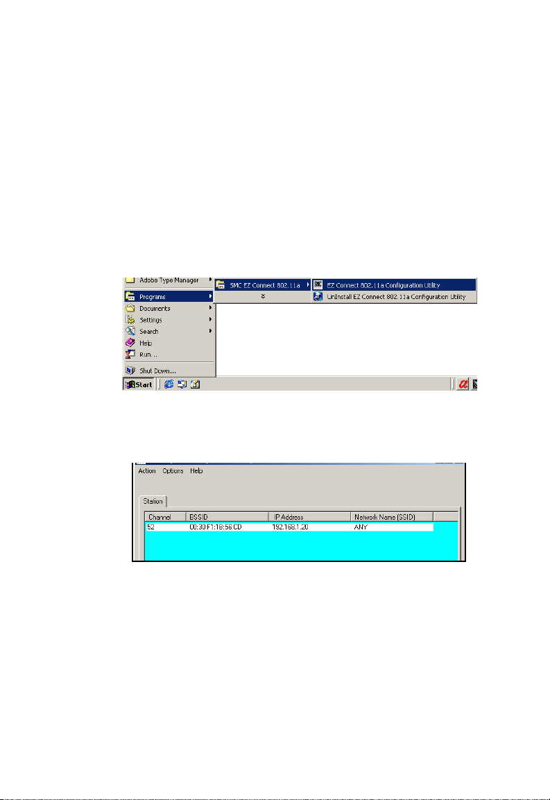
2. After you finish the installed utility, choose “Programs,” then
“SMC EZ Connect 802.11a,” and select “EZ Connect 802.11a
Configuration Utility,” from the “Start” menu.
3. The program will then detect all the SMC2755W Wireless
Access Point(s) on the network. (Default SMC2755W IP
address is “192.168.1.20”.)
4. If DHCP is turned “ON” (default setting is “Disable,” page 21)
and a DHCP server is located on the network, then the Access
Point will automatically be assigned an IP address when
booted. From the list of detected devices (see the above
screen), select and double-click on the unit you want to
configure.
9
Page 18

EZ C
ONNECT
™ 802.11A W
5. The Web management window will appear.
You can also manually launch a web browser from a PC and
enter the IP address that is assigned to the SMC2755W. The
SMC2755W 802.11a AP Web-based configuration page will be
displayed.
IRELESS ACCESS POINT
Setup Wizard
1. To access the Access Point’s management interface, enter the
username “Admin” with a password “5up” and click “Login.”
2. The home page displays the Main Menu on the screen.
10
Page 19

S
YSTEM CONFIGURATION
3. Click on “Setup Wizard” to display basic configurations
including SSID, Channel, Authentication Type and Standard
WEP Setup.
4. Click on the “Next” button to start using the “1-2-3 Setup
Wizard.”
SSID – The Service Set ID. This should be set to the same
value as other wireless devices in your network. (Default:
ANY)
Note: The SSID is upper/lower case sensitive and can consist of
11
Page 20

EZ C
ONNECT
™ 802.11A W
up to 32 alphanumeric characters.
Channel – You can select “Enable” to have the Access Point
operating in turbo mode with data rate up to 72 Mbps.
(Default: Disable)
IRELESS ACCESS POINT
12
Authentication Type – Click on the “Shared Key” radio
button to start filtering the frames with the addresses defined
Page 21

S
YSTEM CONFIGURATION
in the “Standard WEP Setup” screen. (Default: Open System)
13
Page 22

EZ C
ONNECT
™ 802.11A W
Standard WEP Setup – For more secure data transmission,
click on the “Enable” radio button to ensure wireless network
security. Then select one shared key (1 ~ 4) and the proper
key size. (WEP Default: Disable)
Wired Equivalent Privacy (WEP) is implemented in this device
to prevent unauthorized access to your wireless network. The
WEP setting must be the same on each client in your wireless
network.
IRELESS ACCESS POINT
64-Bit Manual Entry
Key 1~4 - Each Key ID contains 10 HEX digits. All wireless
devices must have the same Key ID values to communicate.
128-Bit Manual Entry
Key ID contains 26 HEX digits. All wireless devices must have
the same Key ID values to communicate.
152-Bit Manual Entry
Key ID contains 32 HEX digits. All wireless devices must have
the same Key ID values to communicate.
5. Click on the “Finish” button when completed.
14
Page 23

S
YSTEM CONFIGURATION
Advanced Setup
Click the “Advanced setup” on the right bottom corner to display
additional information about the Access Point configuration as
shown below:
15
Page 24

EZ C
ONNECT
™ 802.11A W
Note: The “Advanced Setup”
screen allows you to view
and change the current
configurations of the
Access Point. After
modifying the
configuration parameters, you must click on the “Apply”
button to save the changes. The new settings will not take
effect until you click “Apply” to refresh the Access Point.
Then you need to click “Reboot” button to reboot the
access point. The web browser loses connectivity with the
AP web server as the access point reboots. To establish a
network connection to the rebooted access point, wait until
it has completed rebooting.
IRELESS ACCESS POINT
Identification
The SSID (Service Set Identification) is the name of a basic service
set provided by an Access Point. All clients that want to connect to
the Internet via an Access Point must set their SSIDs as the same as
that of the Access Point.
SSID: The Service Set ID. This should be set to the same value as
other wireless devices in your network. (Default: ANY).
16
Page 25

S
YSTEM CONFIGURATION
Channel
Radio Channel: The radio channel through which the Access Point
communicates to PCs in its BSS. (Default: “52” for US and “38” for
Japan) Note that the DC channel for wireless clients is
automatically set to the same as that used by the Access Point to
which it is linked.
Note: The available channel settings are limited to local
regulations, which determine the number of channels that
are available.
- FCC: 8 channels
- MKK: 5 channels
Turbo Mode: You may either “Enable” or “Disable” the “Turbo
Mode.” (Default: Disable)
The “Turbo Mode” is the enhanced wireless LAN operating mode
(not regulated in the standard IEEE 802.11a) that can provide a
higher data rate. The “Normal Mode” of the 802.11a access point
provides connections up to 54 Mbps. Enabling the “Turbo Mode”
on the 802.11a Access Point allows the AP to provide connections
up to 72 Mbps data rate.
17
Page 26

EZ C
ONNECT
™ 802.11A W
Note: During “Normal Mode,” the channel bandwidth is 20MHz.
During “Turbo Mode,” the channel bandwidth is increased
to 40MHz. However, there will only be three channels
available when the “Turbo Mode” is enabled (Only 1
channel in Japan).
IRELESS ACCESS POINT
Performance
Data Rate: Select “best” from the drop-down list to
optimize the data transfer speed for your network.
(Default: best)
Transmit Power: Set the signal strength transmitted
from the Access Point. The longer transmission
distance, the higher transmission power required.
(Default: full)
Selections - “full,” “half,” “quarter” and “eighth”
18
Page 27

S
YSTEM CONFIGURATION
Synchronization
In order to obtain transmission, the Access Point and connected
clients need to be synchronized.
Beacon Interval (20-1000): Set the interval value of beacon
between synchronized frames. These synchronous frames also
contain indication of frames that need to transmit to the
power-saved stations. (Default: 100)
DTIM (1-16384): Set the Delivery Traffic Indication Message
(DTIM) interval value. The DTIM indicates how often the MAC
layer forwards multicast traffic. This parameter is necessary to
accommodate stations using Power Save mode. In order to
maximize the utilization of channels, broadcast data is not
transmitted every beacon for stations in Power Save mode. These
power-saved stations must wake up to receive broadcast data at
the DTIM interval.
19
Page 28

EZ C
ONNECT
™ 802.11A W
The DTIM is the interval between two synchronous frames with
broadcast information. If you set the value to 2, the access point
will save all multicast frames for the BSS and forward them after
every second beacon. Having smaller DTIM intervals delivers
multicast frames in a more timely manner, causing stations in
Power Save mode to wake up more often and drain power faster.
Having higher DTIM values, though, delays the transmission of
multicast frames.
(Default: 1)
IRELESS ACCESS POINT
Transmit Threshold
Fragment Length (256-2346): The “Fragment Length” can be set
between 256 and 2,346. If the packet size is smaller than the preset
Fragment size, the packet will not be segmented.
Fragmentation of the PDUs can increase the reliability of
transmission because it increases the probability of a successful
transmission due to smaller frame size. If there is significant
interference present or collisions due to high network utilization,
try setting the fragment size to send smaller fragments. This will
enable the retransmission of smaller frames much faster. However,
it is more efficient to set the fragment size larger if very little or no
interference is present because it requires overhead to send
multiple frames. (Default: 2346)
20
Page 29

S
YSTEM CONFIGURATION
RTS Length (256-2346): Set the RTS (Request to Send) frame
length.
You may configure the access point to initiate an RTS frame
sequence always, never, or only on frames longer than a specified
length. If the packet size is smaller than the preset RTS threshold
size, the RTS/CTS mechanism will NOT be enabled
The access point sends request to send (RTS) frames to a particular
receiving station to negotiate the sending of a data frame. After
receiving an RTS, the station send a CTS (Clear to Send) frame to
acknowledge the right for the sending station to send data frames.
The access point contending for the medium may not be aware of
each other. The RTS/CTS mechanism can solve this “Hidden Node
Problem.” (Default: 2346)
TCP / IP Settings
Set the TCP/IP configuration for accessing the Internet.
With DHCP Client “Enable,” the IP address, subnet mask and
default gateway can be dynamically assigned to the Access Point
21
Page 30

by the network DHCP server. (Default: Disable)
Note: If there is no DHCP server on your network, then the
access point will automatically start up with its default IP
address, 192.168.1.20.
By using the Wireless Access Point’s built-in DHCP (Dynamic Host
Configuration Protocol) server, you are allowing the Wireless
Access Point to handle all the IP addressing on your Local Area
Network (LAN). This can save you much of the time and hassle of
setting up your network. If you have a server on your network that
requires a static IP address, you may still use the “DHCP Server”
and manually assign a static IP address to your server. (Default:
Disable)
22
Page 31

S
YSTEM CONFIGURATION
Encryption
Wired Equivalent Privacy (WEP) is implemented in this device to
prevent unauthorized access to your wireless network. The WEP
setting must be the same on each client in your wireless network.
For more secure data transmission, you may set the WEP to
prevent unauthorized access to your wireless network.
Authentication Type
You may choose either the “Open System” or the “Shared Key.”
(Default: Open System)
23
Page 32

EZ C
ONNECT
™ 802.11A W
If Shared Key is enabled, the WEP should be enabled and at least
one shared key should be defined. But you can enable WEP, and
set the authentication type as open system.
Standard WEP Setup (WEP Default: Disable)
Default Shared Key – Choose the Shared Key that has the
encryption string you prefer (Key 1~4).
64-Bit Manual Entry
Key 1~4 - Each Key ID contains 10 HEX digits. All wireless
devices must have the same Key ID values to communicate.
128-Bit Manual Entry
Key ID contains 26 HEX digits. All wireless devices must have
the same Key ID values to communicate.
152-Bit Manual Entry
Key ID contains 32 HEX digits. All wireless devices must have
the same Key ID values to communicate.
Advanced WEP Setup
How to setup the Unique Key WEP:
IRELESS ACCESS POINT
1. Select a unique key (5 ~ 64)
2. Enter the encryption key and select the proper key size.
3. Click “Write” and “Apply” to save the encryption key.
4. If you want to read an encryption key, select the unique key
you want to read, click “read” and “Apply” to read the
encryption key.
5. If you want to delete an encryption key, select the unique key
you want to delete, click “Delete” and “Apply” to delete the
encryption key.
24
Page 33

S
YSTEM CONFIGURATION
Using MAC Filter
Set the MAC filter to filter out specified MAC addresses. The Access
Control List (ACL) provides a mechanism to take certain actions
based on the stations MAC address. Any frames with a source or
destination MAC address entered in this table will be filtered from
the Access Point.
How to Setup the Access Control List:
1. Select ACL “Enable.”
2. Enter an ACL ID (1 ~ 60)
3. Enter the MAC address of the station you want to setup.
4. Enter Key Map, should be one of the shared key (1 ~ 4) or one
of the unique key (5 ~ 64), and choose “Allow” or “Deny.” It
means if the station’s WEP key is the same as the Key Map you
assigned, the station will allow connecting to the AP or deny
connecting to the AP.
5. If you just enable the ACL, all stations that have shared keys
can also connect to the AP. If you set the ACL to “Strict,” only
stations that MAC addresses in the ACL can connect to the AP.
25
Page 34

EZ C
ONNECT
™ 802.11A W
IRELESS ACCESS POINT
SNMP
Use this screen to display and enter a community string for the
Simple Network Management Protocol (SNMP). To communicate
with the Access Point, the SNMP agent must first be enabled, and
the Network Management Station must submit a valid community
string for authentication.
System
Change Password
Use this screen to change the password on the Access Point.
26
Page 35

S
YSTEM CONFIGURATION
Factory Default
Use the “Restore” button to load the factory default configuration
and reboot this device. Note that all user configured information
will be lost. You will also have to re-enter the password to regain
management access to this device.
Upgrade Firmware
Click “Browse” to locate the downloaded firmware file and press
“Start Upgrade” to start the upgrade process.
For latest firmware version information, visit SMC’s Web site at:
www.smc.com
Status
Clicking on the “Status” radio button on the home page displays
additional information about the Access Point Status and Station
Status as shown in the following section:
27
Page 36

Access Point Status
In the “AP Status” page, click the appropriate hyperlink to view the
Access Point configuration, Access Point SME statistics (station
association information), or Access Point (transmit and receive)
statistics.
AP Configuration
View the access point configuration
28
Page 37

S
YSTEM CONFIGURATION
AP SME (Station Management Entity)
View the station association information
AP Statistics
View the transmit and receive statistics
Connected Station Status
In the “Station Status” page, click the appropriate hyperlink to
view the station configuration, station SME statistics, and station
statistics. The “Station Statistics” page displays transmit and receive
statistics for all associated stations. The page is automatically
refreshed every five seconds.
29
Page 38

EZ C
ONNECT
™ 802.11A W
Station Configuration
Station SME
IRELESS ACCESS POINT
30
Page 39

Station Statistics
S
YSTEM CONFIGURATION
31
Page 40

EZ C
ONNECT
™ 802.11A W
N
ETWORK
IRELESS ACCESS POINT
C
ONFIGURATION
AND
SMC’s EZ Connect Wireless Solution supports a stand-alone
wireless network configuration as well as an integrated
configuration with 10/100 Mbps Ethernet LANs.
The SMC wireless network cards, adapters, access points and
Wireless Access Point can be configured as:
• Ad-hoc for departmental or SOHO LANs
• Infrastructure for wireless LANs
• Infrastructure wireless LAN for roaming wireless PCs
P
LANNING
32
Page 41

N
ETWORK CONFIGURATION AND PLANNING
Network Topologies
Ad-hoc Wireless LAN (no AP or Bridge)
An ad-hoc wireless LAN consists of a group of computers, each
equipped with a wireless adapter, connected via radio signals as
an independent wireless LAN. Computers in a specific ad-hoc
wireless LAN must therefore be configured to the same radio
channel. An ad-hoc wireless LAN can be used for a branch office
or SOHO operation.
Ad-hoc Wireless LAN
Notebook with
Wireless USB Adapter
Notebook with
Wireless PC Card
PC with Wireless
PCI Adapter
33
Page 42

Infrastructure Wireless LAN
The SMC2755W can also provide access to a wired LAN for
wireless workstations. An integrated wired/wireless LAN is called
an Infrastructure configuration. A Basic Service Set (BSS) consists
of a group of wireless PC users, and an access point that is directly
connected to the wired LAN. Each wireless PC in this BSS can talk
to any computer in its wireless group via a radio link, or access
other computers or network resources in the wired LAN
infrastructure via the access point.
The infrastructure configuration not only extends the accessibility
of wireless PCs to the wired LAN, but also increases the effective
wireless transmission range for wireless PCs by passing their signal
through one or more access points.
A wireless infrastructure can be used for access to a central
database, or for connection between mobile workers, as shown in
the following figure.
Wired LAN Extension
to Wireless Adapters
File
Server
Desktop PC
Switch
Notebook with Wireless
PC Card Adapter
34
Access Point
PC with Wireless
PC I Adapter
Page 43

N
ETWORK CONFIGURATION AND PLANNING
Infrastructure Wireless LAN for Roaming Wireless PCs
The Basic Service Set (BSS) is the communications domain for
each Wireless Access Point. For wireless PCs that do not need to
support roaming, set the domain identifier (SSID) for the wireless
card to the BSS ID of the Access Point to which you want to
connect. Check with your administrator for the BSS ID of the
access point or bridge to which he wants you to connect.
A wireless infrastructure can also support roaming for mobile
workers. More than one access point can be configured to create
an Extended Service Set (ESS). By placing the access points so that
a continuous coverage area is created, wireless users within this
ESS can roam freely. All SMC wireless network cards and adapters
and SMC2755W Wireless Access Point within a specific ESS must
be configured with the same SSID.
File
Server
Desktop PC
Switch
Notebook with Wireless
PC Card Adapter
Switch
PC with Wireless
PC I Adapter
Access Point
Notebook with Wireless
PC Card Adapter
<BSS1>
Access Point
<ESS>
Seamless Roaming
<BSS2>
35
Page 44

EZ C
ONNECT
™ 802.11A W
Check the following items before you contact SMC Technical
Support.
1. If mobile users do not have roaming access to the SMC2755W
Wireless Access Point, check the following:
Make sure that all the SMC2755Ws and wireless devices in the
ESS in which the WLAN mobile users can roam are configured
to the same WEP setting, SSID, and authentication algorithm.
2. If the SMC2755W cannot be configured using the Web browser
(page 10):
• Remove power from the SMC2755W.
• Push in the reset button located on the back of the
SMC2755W to restore the factory default settings.
IRELESS ACCESS POINT
T
ROUBLESHOOTING
36
• Plug the power connector back to the Access Point.
Page 45

SMC Networks
802.11a Wireless Products Maximum Distance Table
Important Notice
Maximum distances posted below are actual tested distance
thresholds. However, there are many variables such as barrier
composition and construction and local environmental
interference that may impact your actual distances and cause you
to experience distance thresholds far lower than those we post
below. If you have any questions or comments regarding the
features or performance of this product, or if you would like
information regarding our full line wireless products, you can visit
us on the Web of www.smc.com or you can call us toll-free at
800.SMC.4YOU. SMC Networks stands behind this and every
product we sell with a 30 day satisfaction guarantee and with a
limited-lifetime warranty.
SMC 802.11a Wireless Products Maximum Distance Table
Speed and Distance Ranges
Environmental
Condition
Outdoor
Environment
1
72
Mbps
35 m
(115 ft)
54
Mbps
40 m
(132 ft)
48
Mbps
221 m
(726 ft)
36
Mbps
251 m
(825 ft
24
Mbps
322 m
)
(1056 ft)
18
Mbps
350 m
(1155 ft)
12
Mbps
382 m
(1254 ft)
9 Mbps 6 Mbps
453 m
(1485 ft)
503 m
(1650 ft)
Indoor
Environment
Notes: 1. Outdoor Environment: A line-of-sight environment with no
12 m
18 m
25 m
30 m
35 m
2
(40 ft)
(60 ft)
(82 ft)
(99 ft)
interference or obstruction between Access Point and users.
2. Indoor Environment: A typical office or home environment with floor
to ceiling obstructions between Access Point and users.
(115 ft)
40 m
(132 ft)
37
45 m
(149 ft)
48 m
(157 ft)
50 m
(165 ft)
Page 46

EZ C
ONNECT
™ 802.11A W
Model
SMC2755W
Maximum Channels
US & Canada: 8 (normal mode), 3 (turbo mode)
Japan: 5 (normal mode), 1 (turbo mode)
Maximum Clients
64
Operating Range
Up to 1,650 feet
Data Rate
Normal Mode: 6, 9, 12, 18, 24, 36, 48, 54 Mbps per channel
Turbo Mode: 12, 18, 24, 36, 48, 72 Mbps per channel
IRELESS ACCESS POINT
S
PECIFICATIONS
Network Configuration
Infrastructure
Operating Frequency
5.15 ~ 5.25 GHz (lower band) US/Canada, Japan
5.25 ~ 5.35 GHz (middle band) US/Canada
38
Page 47

Sensitivity
Modulation/Rates Sensitivity (dBm)
BPSK (6Mbps) -85
BPSK (9Mbps) -84
QPSK (12Mbps) -83
QPSK (18Mbps) -81
16 QAM (24Mbps) -78
16 QAM (36Mbps) -74
64 QAM (48Mbps) -69
64QAM(54Mbps) -65
BPSK Turbo (12Mbps) -82
BPSK Turbo (18Mbps) -81
QPSK Turbo (24Mbps) -80
QPSK Turbo (36Mbps) -78
16 QAM Turbo (48Mbps) -75
16 QAM Turbo (72Mbps) -71
S
PECIFICATIONS
39
Page 48

EZ C
ONNECT
™ 802.11A W
Modulation
IRELESS ACCESS POINT
Modulation 5.15-5.25GHZ
(dBm)
BPSK(6Mbps) 16 20
BPSK(9Mbps) 16 20
QPSK(12Mbps) 16 19
QPSK(18Mbps) 16 19
16 QAM(24Mbps) 16 18
16 QAM(36Mbps) 16 18
64 QAM(48Mbps) 16 16
64 QAM(64Mbps) 14 14
BPSK Turbo(12Mbps) 16 20
BPSK Turbo(18Mbps) 16 20
QPSK Turbo(24Mbps) 16 19
QPSK Turbo(36Mbps) 16 19
16 QAM Turbo(48Mbps) 16 18
16 QAM Turbo(72Mbps) 16 18
5.25-5.35GHZ
(dBm)
40
Page 49

Power supply
Input: 100-240 AC, 50-60 Hz;
Output: 3.3 V DC, 4A
Output Power
16 dBm minimum
Physical Size
8.07 x 5.35 x 1.58 in, (20.5 x 13.6 x 4 cm)
Weight
9.9 oz (280 grams)
LED Indicators
Power, Ethernet Link/Activity, Wireless Link/Activity
Network Management
HTML Web-browser interface,
Windows 98/NT/2000/Me/XP utility
Operating Systems
Windows 98/NT/2000/Me/XP
S
PECIFICATIONS
Temperature
Operating: 32 to 122
Storage: 32 to 158
Humidity
5% to 95% (non-condensing)
Compliances
IEC 61000-4-2/3/4/6/11
ºF (0 to 50 ºC),
ºF (0 to 70 ºC)
41
Page 50

EZ C
ONNECT
™ 802.11A W
Emissions
ETS 300 328
RCR STD-33A
Safety
CSA/NTRL (CSA 22.2 No. 950 & UL 1950)
EN60950 (T
Standards
IEEE 802.3 10BASE-T, IEEE 802.3u 100BASE-TX, IEEE 802.11a
Warranty
Limited Lifetime
ÜV/GS), IEC60950 (CB)
IRELESS ACCESS POINT
42
Page 51

T
ERMINOLOGY
T
ERMINOLOGY
The following is a list of terminology that is used in this document.
Access Point – An internetworking device that seamlessly
connects wired and wireless networks.
Ad-Hoc – An Ad-Hoc wireless LAN is a group of computers each
with LAN adapters, connected as an independent wireless LAN.
Backbone – The core infrastructure of a network. The portion of
the network that transports information from one central location
to another central location where it is unloaded onto a local
system.
Base Station – In mobile telecommunications, a base station is the
central radio transmitter/receiver that maintains communications
with the mobile radiotelephone sets within its range. In cellular
and personal communications applications, each cell or micro-cell
has its own base station; each base station in turn is
interconnected with other cells’ bases.
BSS – BSS stands for “Basic Service Set.” It is an Access Point and
all the LAN PCs that are associated with it.
CSMA/CA – Carrier Sense Multiple Access with Collision
Avoidance.
ESS – ESS (ESS-ID, SSID) stands for “Extended Service Set.” More
than one BSS is configured to become an Extended Service Set.
LAN mobile users can roam between different BSSs in an ESS
(ESS-ID, SSID).
43
Page 52

EZ C
ONNECT
™ 802.11A W
Ethernet – A popular local area data communications network,
which accepts transmission from computers and terminals.
Ethernet operates on a 10 Mbps base band transmission rate, using
a shielded coaxial cable or over shielded twisted pair telephone
wire.
Infrastructure – An integrated wireless and wired LAN is called
an Infrastructure configuration.
Roaming – A wireless LAN mobile user moves around an ESS and
maintains a continuous connection to the Infrastructure network.
RTS Threshold – Transmitters contending for the medium may
not be aware of each other. RTS/CTS mechanism can solve this
“Hidden Node Problem.” If the packet size is smaller than the
preset RTS Threshold size, the RTS/CTS mechanism will NOT be
enabled.
WEP – “Wired Equivalent Privacy” is based on the use of 64-bit,
128-bit or 152-bit keys and the popular RC4 encryption algorithm.
Wireless devices without a valid WEP key will be excluded from
network traffic.
IRELESS ACCESS POINT
44
Page 53

Page 54

FOR TECHNICAL SUPPORT, CALL:
From U.S.A. and Canada (24 hours a day, 7 days a week)
(800) SMC-4-YOU; (949) 707-2400; (949) 707-2460 (Fax)
From Europe (8:00 AM - 5:30 PM UK Greenwich Mean Time)
44 (0) 1188 748740; 44 (0) 1189 748741 (Fax)
INTERNET
E-mail address:
techsupport@smc.com
tech.support@smc-europe.com
Driver updates:
http://www.smc.com/index.cfm?action=tech_support_drivers_downloads
World Wide Web:
http://www.smc.com/
FOR LITERATURE OR ADVERTISING RESPONSE, CALL:
U.S.A. and Canada: (800) SMC-4-YOU; Fax (949) 707-2460
Spain: 34-93-477-4920; Fax 34-93-477-3774
UK: 44 (0) 1188 748700; Fax 44 (0) 1189 748701
Southern Europe: 33 (1) 41.18.68.68; Fax 33 (1) 41.18.68.69
Central/Eastern Europe: 49 (0) 89 92861-130; Fax 49 (0) 89 92861-230
Nordic: +46 (0) 868 70 700; Fax +46 (0) 887 62 62
Middle East: 971-48818410; Fax 971-48817993
South Africa: +27.11.314.1133; Fax +27.11.314.9133
PRC: 86-10-6235-4958; Fax 86-10-6235-4962
Taiwan: 886-2-2659-9669; Fax 886-2-2659-9666
Asia Pacific: (65) 238 6556; Fax (65) 238 6466
Korea: 82-2-553-0860; Fax 82-2-553-7202
Japan: 81-45-224-2329; Fax 81-45-224-2344
Australia: 61-2-9416-0437; Fax 61-2-9416-0474
India: 91-22-8204437; Fax 91-22-8204443
6 Hughes
Irvine, CA 92618
Phone: (949) 707-2400
Model Number: SMC2755W
Pub #: 150000013800A
Part No: 01-111320-006
Revision Number: F1.1.1 E122001-R01
 Loading...