

Page 1
SMC2602W
Page 2

Copyright Information furnished by SMC Networks, Inc. (SMC) is believed to be accurate and reliable. However, no responsibility is assumed by SMC for its use, nor for any infringements of patents or other rights of third parties which may result from its use. No license is granted by implication or otherwise under any patent or patent rights of SMC. SMC reserves the right to change specifications at any time without notice.
Copyright © 2003 by
SMC Networks, Inc.
38 Tesla
Irvine, California 92618
All rights reserved.
Trademarks
SMC® is a registered trademark; and EZ-Stream, EZ Connect, Barricade and EZ Hub are
trademarks of SMC Networks, Inc. Other product and company names are trademarks or
registered trademarks of their respective holders.
Page 3

Compliances
FCC - Class B
This equipment has been tested and found to comply with the limits for a Class B digital device,
pursuant to Part 15 of the FCC Rules. These limits are designed to provide reasonable protection
against harmful interference in a residential installation. This equipment generates, uses and can
radiate radio frequency energy and, if not installed and used in accordance with instructions, may
cause harmful interference to radio communications. However, there is no guarantee that the
interference will not occur in a particular installation. If this equipment does cause harmful
interference to radio or television reception, which can be determined by turning the equipment
off and on, the user is encouraged to try to correct the interference by one or more of the
following measures:
• Reorient the receiving antenna
• Increase the separation between the equipment and receiver
• Connect the equipment into an outlet on a circuit different from that to which
the receiver is connected
• Consult the dealer or an experienced radio/TV technician for help
FCC Caution: To assure continued compliance, (for example - use only shielded interface cables
when connecting to computer or peripheral devices). Any changes or modifications not expressly
approved by the party responsible for compliance could void the user’s authority to operate this
equipment.
This device complies with Part 15 of the FCC Rules. Operation is subject to the following two
conditions: (1) This device may not cause harmful interference, and (2) this device must accept
any interference received, including interference that may cause undesired operation.
CAUTION STATEMENT:
FCC Radiation Exposure Statement
This equipment complies with FCC radiation exposure limits set forth for an uncontrolled
environment. This equipment should be installed and operated with a minimum distance of 5
centimeters between the radiator and your body. This transmitter must not be co-located or
operating in conjunction with any other
antenna or transmitter. Note: In order to maintain compliance with the limits of a Class B digital
device, SMC requires that you use a quality interface cable when connecting to this device.
Changes or modifications not expressly approved by SMC could void the user’s authority to
operate this equipment.
Attach unshielded twisted-pair cable (UTP) to the RJ-45 port and shielded USB cable to the USB
port.
Industry Canada - Class B
This digital apparatus does not exceed the Class B limits for radio noise emissions from digital
apparatus as set out in the interference-causing equipment standard entitled “Digital Apparatus,”
ICES-003 of Industry Canada.
Cet appareil numérique respecte les limites de bruits radioélectriques applicables aux appareils
numériques de Classe B prescrites dans la norme sur le matérial brouilleur: “Appareils
Numériques,” NMB-003 édictée par l’Industrie.
Page 4

1 | System Requirements
• Available Bus-Mastered PCI slot
• Windows 98SE/Me/2000/XP
• Another IEEE 802.11b compliant device installed in your network, such as the
SMC7004VWBR Barricade Wireless Cable/DSL Broadband Router, or another PC with a
wireless adapter, such as the SMC2662W EZ Connect Wireless USB Adapter.
2 | Equipment Checklist
After unpacking the SMC2602W EZ Connect 2.4GHz 11Mbps Wireless PCI Card, check the
contents of the box to be sure you have received the following components:
• 1 SMC2602W Wireless PCI Card
• 1 Driver, Utility, and Documentation CD
• 1 Quick Install Guide
Immediately inform your dealer in the event of any incorrect, missing or damaged parts. If
possible, please retain the carton and original packing materials in case there is a need to return
the product.
Please register this product and upgrade the product warranty at SMC's Web site:
http://www.smc.com
Page 5
3 | Installation Instructions
Warning:
Network cards are sensitive to static electricity. To protect the card, avoid touching its electrical
components and always touch the metal chassis of your computer before handling the card.
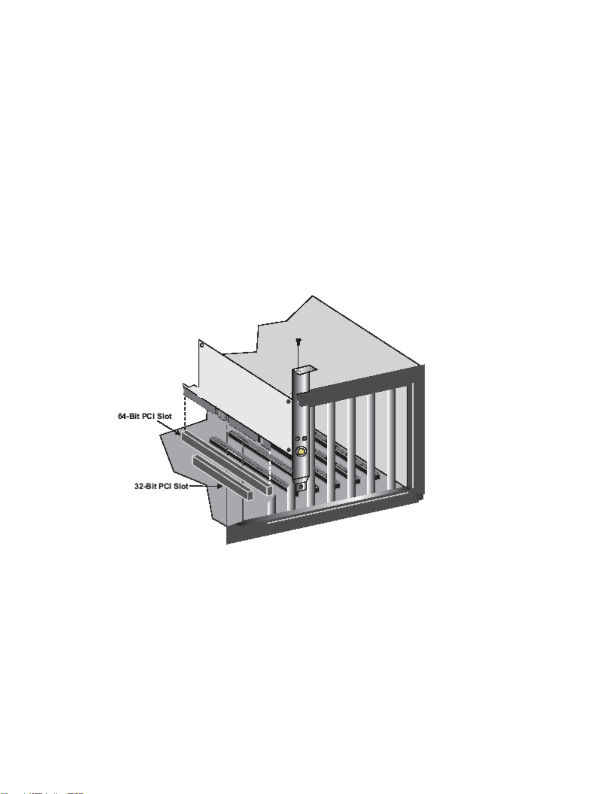
1) Switch off the computer, unplug the power cord, and remove the computer's cover.
2) Select an unused PCI bus-master slot and remove its protective bracket.
3) Carefully insert the card and press until all the edge connections are firmly seated inside
the slot. Then screw the card's bracket securely into the PC's chassis.
4) Replace the computer's cover and power it on. The SMC2602W should be automatically
configured by the host computer's BIOS. However, if you have an older computer, you
may have to manually configure the computer's BIOS settings.
Page 6
4 | Driver Installation
NOTE: Installation processes will require the use of your original, licensed copy of Windows.
Please have your Windows CD available BEFORE proceeding with the installation.
Windows 98
Step 1: After you have inserted the SMC2602W 11Mbps Wireless PCI Card in your machine, the
Operating System will automatically recognize the adapter and prompt you for the appropriate
drivers. Click the [Next >] button to begin the installation.
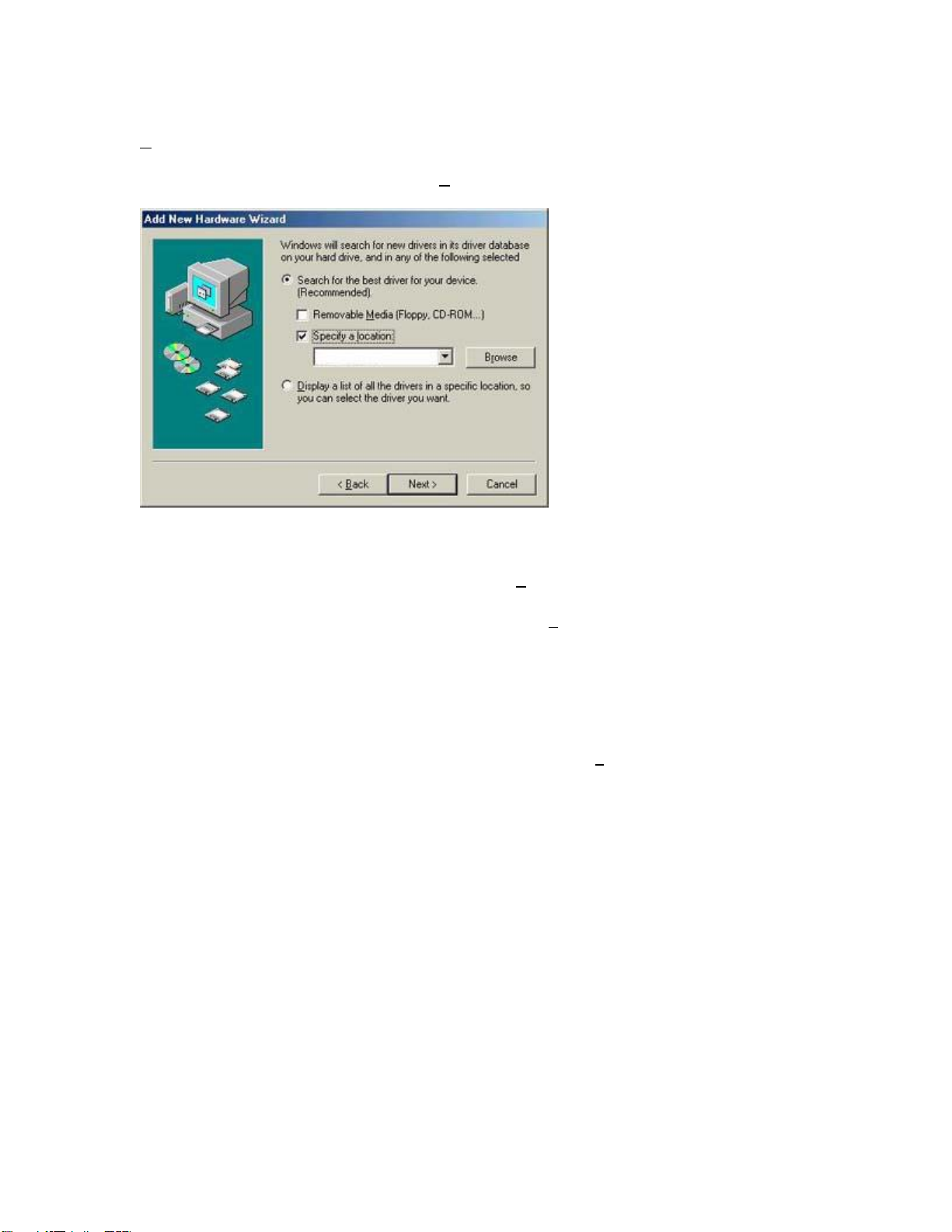
Step 2: Insert the Driver CD and select the [Search for the best driver for your device] option
and click [Next >].
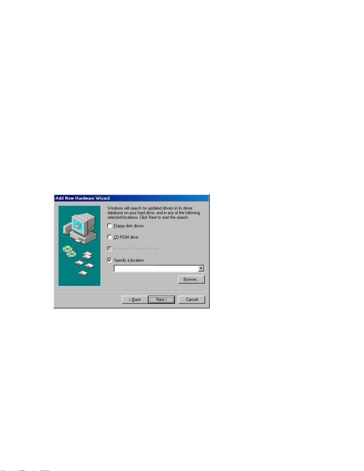
Step 3: Clear all checkboxes except for [Specify a location:]. Then press the [Browse] button
and look for the drivers on your CD-ROM. Browse to ?:\SMC2602W\WIN9XME. (Note: The "?"
equals the letter of your CD-ROM drive. In most cases, this is D.)
Figure 1.0
Step 4: The system should find the drivers. Click the [Next >] button to continue the installation.
The wizard will show "SMC2602W 11Mbps Wireless PCI Card".
(Note: If the system could not find the drivers, click the [< Back] button, and select the [Display
a list of all the drivers...] option. Select [Network Adapters] from the list of devices, press [Have
Disk] and once again browse to the location of the drivers)
Page 7
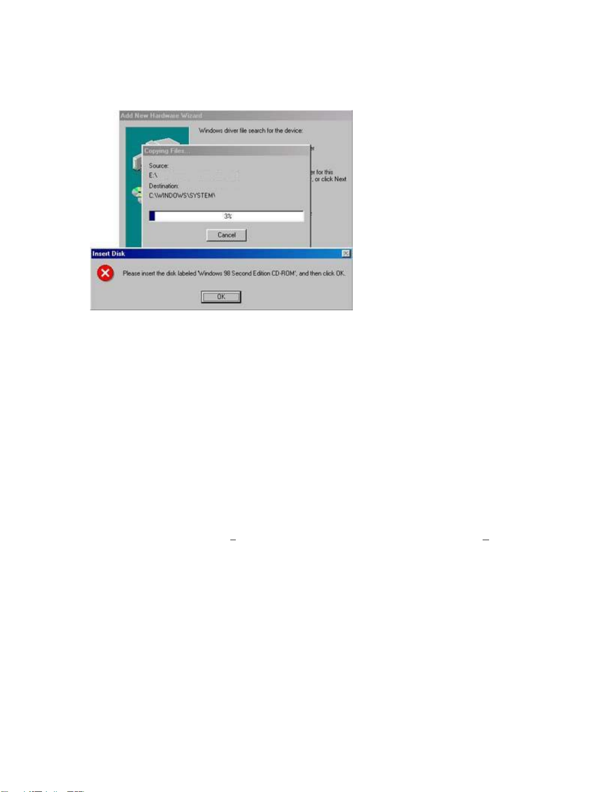
Step 5: Once the system has copied the SMC drivers from the CD, it may then request files from
your original Windows disk. Please insert the Windows CD at this time.
Figure 1.1
Step 6: The system will copy the files. Do NOT press [Cancel].
Step 7: Once all the necessary files are copied from the Windows CD, the driver install process
will be complete. Click [Finish] to exit the wizard.
Step 8: You will then be prompted to reboot the machine. Press [Yes]. Upon reboot, the
SMC2602W 11Mbps Wireless PCI Card will be initialized and ready for use.
Windows ME
Step 1: After you have inserted the SMC2602W 11Mbps Wireless PCI Card in your machine and
turned it back on, the OS will automatically recognize the adapter and prompt you for the
appropriate drivers. Select the [S
pecify the location of the driver] option. Then click the [Next >]
button to begin the installation.
Page 8
Step 2: Insert the Driver CD and select the [Specify a location:] option. Clear the [Removable
edia] checkbox. Then press the [Browse] button and look for the drivers on your CD. This
M
should be located in ?:\SMC2602W\WIN9XME. (Note: The ? equals the letter of your CD-ROM
drive. In most cases, this is D.) Then click [N
ext >].
Figure 1.2
Step 3: The system should find the drivers. Click the [Next >] button to continue the installation.
(Note: If the system could not find the drivers, click the [< B
ack] button, and select the [Display
a list of all the drivers] option. Select [Network Adapters] from the list of devices, press [Have
Disk] and once again browse to the location of the drivers)
Step 4: Once all the necessary files have been copied, the driver installation is complete. Click
[Finish] to exit the wizard.
Step 5: You will then be prompted to reboot the machine. Press [Y
es]. Upon reboot, the
SMC2602W will be initialized and ready for use.
Page 9
Windows 2000
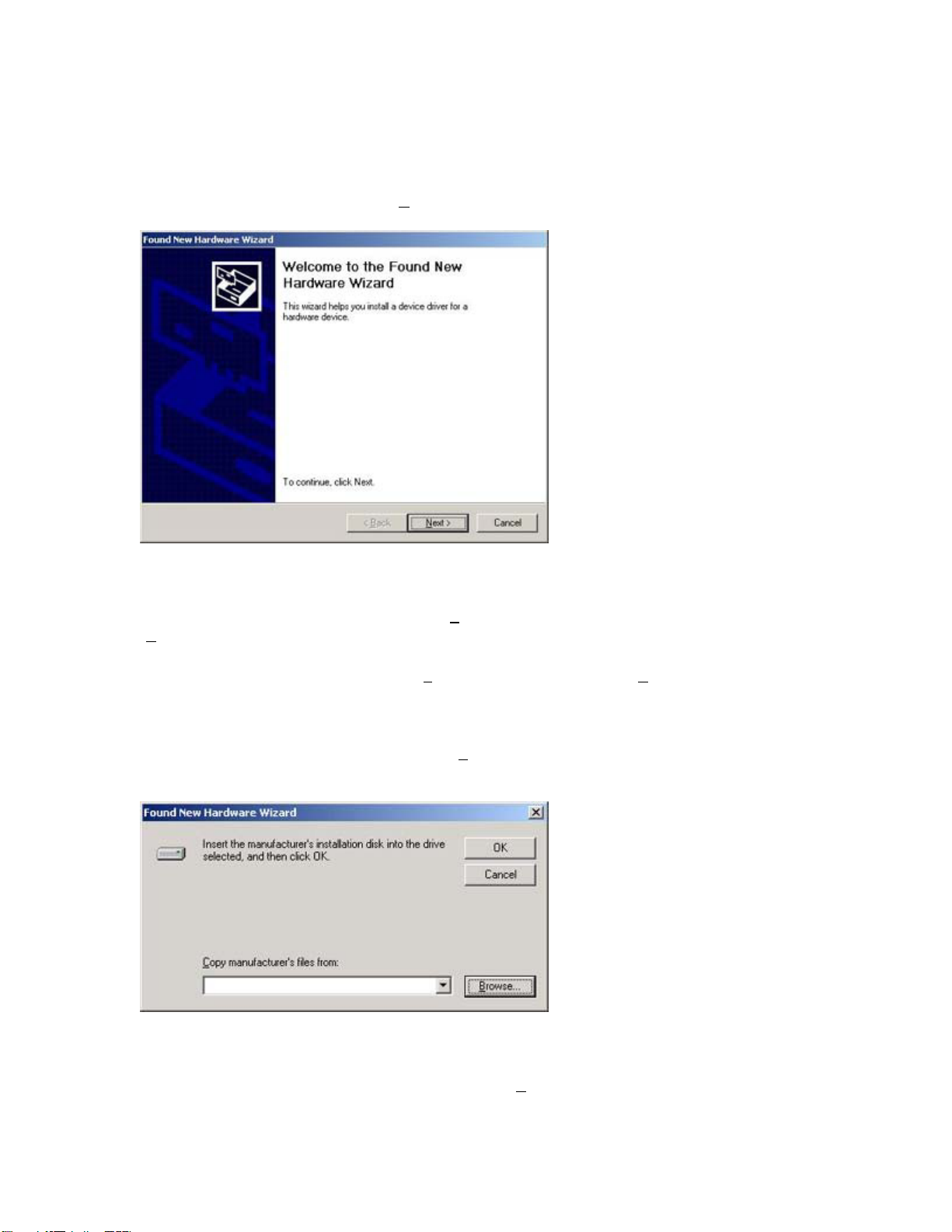
Step 1: After you have inserted the SMC2602W 11Mbps Wireless PCI Card in your machine and
turned it back on, the Operating System will automatically recognize the adapter and prompt you
for the appropriate drivers. Click the [N
ext >] button to begin the installation.
Figure 1.3
Step 2: Insert the Driver CD and select the [Search for a suitable driver...] option. Then click
ext >].
[N
Step 3: Clear all checkboxes except for [S
pecify a location]. Then click [Next >].
Step 4: You will then be prompted to enter the location of the drivers. This should be
?:\SMC2602W\WIN2KXP. (Note: The ? equals the letter of your CD-ROM drive. In most cases,
this is D.) Then click [OK]. You can also click [B
rowse] and browse to the location of the drivers
on the CD for further verification.
Figure 1.4
Step 5: The system should find the drivers. Click the [N
ext >] button to continue the installation.
Page 10
(Note: If the system could not find the drivers, click the [< Back] button, and select the [Display
a list of the known drivers...] option. Select [Network Adapters] from the list of devices, press
[Have Disk] and once again browse to the location of the drivers)
Step 6: You have now completed the driver installation. Click [Finish] to initialize the adapter.
Windows XP
Step 1: After you have inserted the SMC2602W 11Mbps Wireless PCI Card in your machine and
turned it back on, the Operating System will automatically recognize the adapter and prompt you
for the appropriate drivers. Click the [N
ext >] button to begin the installation.
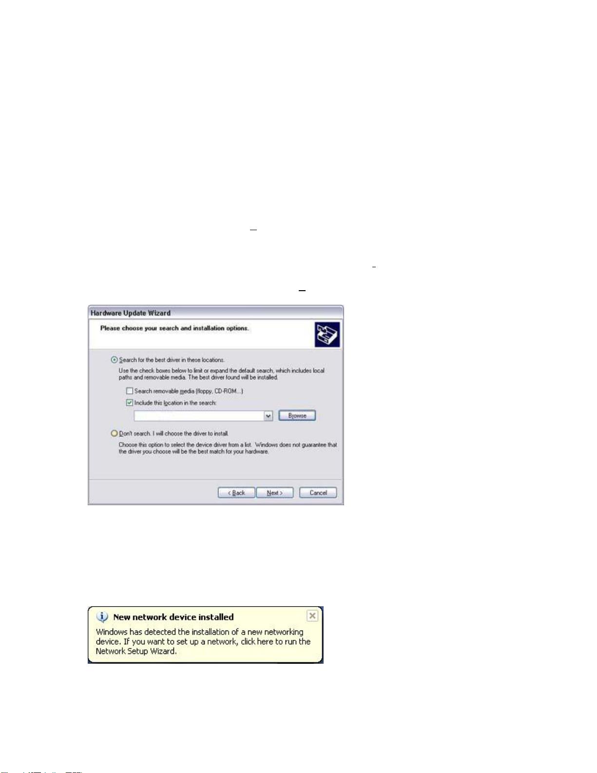
Step 2: Insert the Driver CD and check the [Include this location in the search] option. Make
sure the [Search removable media] option is not checked. Click [Br
owse] and find the location of
the drivers. This should be ?:\SMC2602W\WIN2KXP. (Note: The ? equals the letter of your CDROM drive. In most cases, this is D.) Then click [N
ext >].
Figure 1.5
Step 3: This process will be completed once the drivers are copied to the hard drive and
installed. Please click [Finish] to exit the wizard.
After clicking [Finish], you will see the following message in your system tray:
Page 11

Continue to the "Utility Installation" section for documentation on how to use the utility
application for your Wireless PCI Card.
5 | Verification
Windows 98/Me
Step 1: Right-click the My Computer icon on your desktop and click [Pr
operties].
Figure 1.0
Step 2: Then go to the [Device Manager] tab and open the [Network adapters] section. You
should see your SMC2602W 11Mbps Wireless PCI Card in this menu. Highlight it and click
operties].
[Pr
Step 3: The Device Status shows that the "This device is working properly". If there are any
error messages displayed here, you will need to click the SMC adapter and click [Remove]. Then
reboot the machine and go through the installation process again.
Page 12

Windows 2000
Step 1: Right-click the My Computer icon on your desktop and click [Properties].
Step 2: Then go to the Hardware tab and click [D
section. You should see your SMC2602W 11Mbps Wireless PCI Card in this menu. Right-click your
adapter and click [Properties].
evice Manager]. Open the [Network adapters]
Figure 1.1
Step 3: The Device Status shows that the "This device is working properly". If there are any
error messages displayed here, you will need to right-click the SMC adapter and click [Uninstall].
Then reboot the machine and go through the installation process again.
Page 13

Windows XP
Step 1: Click [Start] and click [Control Panel]. Then click the [Performance and Maintenance]
icon and select [System].
Figure 1.2
Figure 1.3
Step 2: Then go to the Hardware tab and click [Device Manager]. Open the [Network adapters]
section. You should see your SMC2602W 11Mbps Wireless PCI Card in this menu. Right-click the
adapter and click [Properties].
Page 14

Figure 1.4
Step 3: The Device Status shows that "This device is working properly". If there are any error
messages displayed here, you will need to right-click the SMC adapter and click [Uninstall]. Then
reboot the machine and go through the installation process again.
Page 15

6 | Utility Installation
Step 1: Insert the SMC2602W Driver, Utility and Documentation CD.
Step 2: Click the [Install Driver/Utility] button.
Figure 1.0
Step 3: Click [Next >] and then select "Easy" or "Advanced" depending on your level of
networking expertise. If you choose the "Easy" option, the utility will automatically install after
you press [N
the network type, SSID and channel.
ext >]. If you choose "Advanced", you will be asked specific questions concerning
Figure 1.1
Page 16

Step 4: Choose the appropriate network type.
Figure 1.2
Step 5: If you select "Infrastructure", you will need to enter the SSID of your WLAN. Click [N
>] to finish.
Figure 1.3
ext
Step 6: Click [Finish] after the files are copied. You have now completed the utility installation
process.
Page 17

7 | Utility Configuration
When the utility program is running, there will be a quick launch icon in the lower right-hand
corner of the taskbar. The icon will be GREEN if you have a good connection to a wireless
network. If it is red, you will need to verify the network settings and check to be sure that the
Wireless Access Point on your network is turned on. You may also need to re-position the Access
Point and place it in a higher position so that you are able to gain more wireless signal strength.
Double-click the quick launch icon in the system tray to bring up the Configuration Utility. This
provides quick access to management statistics and adapter settings.
The Configuration Utility includes the following tabs:
Configuration: Allows you to implement Profile Management, edit SSID data, change the Tx
Rate and Operating mode, and enable 64/128-bit WEP.
Link Information: Allows you to view/monitor network status, throughput, wireless channel,
and TCP/IP Information.
IP Information: Displays TCP/IP data and allows you to Release and Renew your IP addresses.
Site Survey: Displays all the Access Points within range of the wireless adapter's signal. Allows
you to select your desired WLAN.
Version Information: Shows the driver and utility version information.
Page 18

Section 1.1 | Configuration
When the Configuration Utility is initialized, the Configuration window may be immediately
shown. This will show you the current select profile of the wireless card. Click [New] to enter a
new name for the current profile. Click [Save] to save the current settings to the selected profile.
Click [Delete] to delete the current profile.
Figure 1.0
The options for Operating Mode are "802.11 Adhoc" and "Infrastructure". Adhoc networks consist
of wireless clients only. In Infrastructure networks, wireless clients connect to wired LANs via
Wireless Access Points. The options for Transmit Rate are "Auto", "1 Mbps", "2 Mbps", "5.5
Mbps", and "11 Mbps". The Channel can only be changed when you are connected to a Adhoc
WLAN. The channel must be configured to the same radio channel as that used by the other
wireless clients in your group.
For more secure data transmissions, it is recommended to enable WEP on your WLAN. The utility
supports HEX key entries. For the HEX Key Format, the security is enabled by entering 10-digit
keys for the 64-bit WEP configuration, and 26-digit keys for a 128-bit WEP configuration. Select
the desired encryption strength (64-bit or 128-bit) and then enter the appropriate keys in Key 1,
2, 3, or 4. Remember to select the correct "Default Key" and then click [Apply Changes]. You can
also check the "Passphrase" option and enter the desired value. You must be sure to use the
same passphrase on all other wireless clients/Access Points. A passphrase string can consist of up
to 32 alphanumberic characters.
Page 19

Section 1.2 | Link Information
Figure 1.1
Associated BSS ID: Shows the MAC Address of the associated Access Point
Current Tx Rate: Current transmit rate value
Throughput: Number of packets sent and recieved
SSID: Workgroup name of the wireless network that you are connected to
Link Quality: Shows the relative link quality (e.g., lack of frame errors) of the wireless
connection to the Access Point.
Signal Strength: Shows the relative signal strength of the wireless connection to the Access
Point.
Page 20

Section 1.3 | IP Information
Figure 1.2
The IP Information screen displays network connection information.
Page 21

Section 1.4 | Site Survey
The Site Survey tab scans and displays all Access Points on the wireless LAN. The data is
organized by columns signifying the "SSID", "BSSID", "Channel", "Encryption", "Signal", and
"Network Type". The key symbol in the Encryption column signifies that the network is
encrypted. You will need to obtain the WEP information from the network administrator. To
choose a network, simply double-click the "SSID".
Figure 1.3
Page 22

Section 1.5 | Version Information
The Version Information screen displays the version information.
Figure 1.4
Page 23

8 | Wireless Distance Table
Important Notice
Maximum distances posted below are actual tested distance thresholds. However, there are many
variables such as barrier composition and construction, as well as local environmental
interference that may impact your actual distances and cause you to experience distance
thresholds far lower than those posted
below. If you have any questions or comments regarding the features or performance of this
product, or if you would like information regarding our full line of wireless products, you can visit
us at www.smc.com, or you can call us toll-free at 800.SMC.4YOU. SMC Networks stands behind
every product sold
with a 30-day satisfaction guarantee and a limited-lifetime warranty.
Environmental
Condition
Outdoors: A line-of-
sight
environment with no
interference or
obstruction
between the Access
Point
and users.
Indoors: A typical
office or
home environment
with
floor to ceiling
obstructions
between the Access
Point
and users.
802.11b Wireless Distance Table
Speed and Distance Ranges
11 Mbps 5.5 Mbps 2 Mbps 1 Mbps
160 m
(528 ft)
72 m
(236 ft)
195 m
(640 ft)
73 m
(240 ft)
255 m
(837 ft)
73 m
(240 ft)
350 m
(1,155 ft)
75 m
(246 ft)
Page 24

9 | Troubleshooting
PCI Compatibility
• Early PCI BIOS versions do not properly support the new PCI specifications and may
“hang” when a network card driver tries to load. If this occurs, make sure your BIOS
correctly supports the PCI Local Bus Specification (v2.0 or later) and upgrade your
computer BIOS to the latest version
• Some PCI computers are not self-configuring and require you to perform some or all of
the following functions by motherboard jumper changes and/or BIOS Setup
configuration:
o Verify that the PCI slot is an enabled bus-master slot and not a slave PCI slot.
The SMC2602W must be installed in a PCI bus-master slot. In some computers
the PCI slot must be configured to enable bus mastering. Refer to your PC’s
manual and check the PCI BIOS Setup program to be sure the PCI slot is an
enabled bus-master slot.
o Make sure that your motherboard supports 3.3V PCI cards.
o In some computers, you may be required to disable Plug-and-Play in the BIOS
Setup program if resources are not properly assigned between the network card
and other installed cards.
o Some computers may require you to reserve interrupts and memory addresses
for installed ISA cards to prevent PCI cards from using the same settings. Refer
to your PC’s manual and check the PCI BIOS Setup program configuration
options for ISA cards.
o Make sure the PCI slot is configured to support INTA.
o Ensure that INTA for the slot is assigned to a free interrupt (IRQ) number.
Common Installation Problems
Problems are often caused by cabling errors, conflicts with other devices installed in the same
computer, or software that has been configured incorrectly. If you encounter a problem with the
SMC2602W, use the following checklists to identify and correct the problem.
• If you’re computer cannot find the SMC2602W, or the network driver does not install
correctly, check the following items before contacting SMC Technical Support
o Make sure the card is securely seated in the PCI slot. Check for any hardware
problems, such as physical damage to the card’s edge connector.
o Try the card in another PCI bus-master slot. If this fails, test the card in a
completely different system or try using a second SMC2602W in that particular
bus-master slot.
o Check for resource conflicts in the PCI configuration.
o Make sure your computer is using the latest BIOS available. Contact the
manufacturer of the computer or motherboard for information on updating the
BIOS (e.g. – Dell, Toshiba, etc)
o If there are other network cards in the computer, they may be causing conflicts.
Remove all other cards from the computer and test the SMC2602W separately. If
you continue to have problems, remove all cards except the SMC2602W and your
video card.
Page 25

Network Connection Problems
There may be a network connection problem if the LED on the card does not light, or if you
cannot access any network resources from the computer. Check the following items before
contacting SMC Technical Support.
• Make sure the correct network card driver is installed for your operating system. If
necessary, try uninstalling and reinstalling the driver. To do this, first go into the Device
Manager, select Network Adapters, and remove the SMC adapter. Then open up your
Start Menu, go to Programs, click the "SMC2602W 11Mbps WLAN Utility" program folder
and choose "Uninstall". Reboot the machine when the uninstall is complete. Once you
have booted up again, the OS may ask for the SMC Driver CD again. Insert your Driver
CD and browse to the driver path again. Then install the utility program again.
• Make sure the computer and other network devices are receiving power. If you suspect a
power outlet to be faulty, plug another device into it to verify that it is working.
• If your wireless station cannot communicate with a computer on the Ethernet LAN when
configured for Infrastructure mode, try changing the wireless channel on the AP. Make
sure the SSID is the same as that used by the AP for a station with roaming disabled, or
the same as that used by the AP's in the extended service set (ESS).
• The Access Point you are trying to attach to is defective or may not be configured
properly to accept your signal. Check with the administrator of your wireless network for
more information on connecting to the LAN. Also run the necessary diagnostics on the AP
to make sure the unit is fully operational.
• If you cannot access the Internet, be sure to check with the ISP for further instructions
once the drivers for the Wireless Card are installed properly.
10 | Frequently Asked Questions
• What is a Wireless LAN?
o A local area network that transmits over the air typically in an unlicensed
frequency such as the 2.4GHz band. A wireless LAN does not require lining up
devices for line of sight transmission like IrDA. Wireless access points (base
stations) are connected to an Ethernet hub or server and transmit a radio
frequency over an area of several hundred to a thousand feet which can
penetrate walls and other non-metal barriers. Roaming users can be handed off
from one access point to another like a cellular phone system. Laptops use
wireless network cards that plug into an existing PCMCIA slot or that are self
contained on PC cards, while stand-alone desktops and servers use plug-in cards
(ISA, PCI, etc.).
• What is Ad-hoc?
o An AD-HOC network is a peer to peer network where all the nodes are wireless
clients. As an example, two PC’s with wireless adapters can communicate with
each other as long as they are within range. A wireless extension point can
extend the range of an AD-HOC network.
• What is the 802.11 standard?
o A family of IEEE standards for wireless LANs first introduced in 1997. 802.11
provides 1 or 2 Mbps transmission in the 2.4GHz band using either a frequency
hopping modulation (FHSS) technique or direct sequence spread spectrum
(DSSS), which is also known as CDMA. The 802.11b standard defines an 11
Mbps data rate in the 2.4GHz band, and the 802.11a standard defines 54 Mbps
in the 5GHz band.
Page 26

• What is Infrastructure?
o In order for your wireless components to interact with traditional wired networks
they need a media bridge to translate for them. This is where INFRASTRUCTURE
or Network mode comes into play. An ACCESS POINT is attached to the network
using CAT-5 Ethernet cable attaching to a hub, switch or another PC. Wireless
PC’s can then communicate to Wired Ethernet computers through this access
point. The total range of the network is limited to a radius around this Access
Point. To increase the range, extra Access Points may be wired into the network.
These Access Points talk to each other over the hard-wired Ethernet cables
however, they cannot communicate wirelessly to one another and they must be
wired to the same network. Individual wireless PC’s can move between Access
Points on the same network seamlessly due to a feature called ROAMING.
• What is Tx-Rate?
o Tx-Rate or TRANSFER RATE is the current speed at which the network
component is operating. SMC-802.11b products can operate at speeds of 1Mb,
2Mb, 5.5Mb, & 11Mbps. A wireless card set to AUTO will attempt to connect at
whatever speed will give the best throughput on the network.
• What is RTS Threshold?
o (Request To Send) An RS-232 signal sent from the transmitting station to the
receiving station requesting permission to transmit. RTS is a collision avoidance
method used by all 802.11b wireless networking devices. In most cases you will
not need to activate or administer RTS. Only if you find yourself in an
Infrastructure environment where all nodes are in range of the Access Point but
may be out of range of each other. It is recommended to leave this setting at its
default value leaving this feature disabled.
• What is Authentication Algorithm?
o Authentication Algorithm is the means by which one station is authorized to
communicate with another. In an Open System, any station can request
authorization in accordance with the WECA standard. In a Shared key system,
only stations that possess a secret encrypted key may participate in the network.
This is a low level security key which allows the equipment with the shared key
algorithm to see each other on the wireless lan.
• What is DBI?
o The ability of the antenna to shape the signal and focus it in a particular
direction is called Antenna Gain, and is expressed in terms of how much stronger
the signal in the desired direction is, compared to the worst possible antenna,
which distributes the signal evenly in all directions (an Isotropic Radiator). To
express the relationship to the Isotropic reference, this is abbreviated: "dBi". The
typical omni-directional "stick" antenna is rated at 6-8 dBi, indicating that that by
redirecting the signal that would have gone straight up or down to the horizontal
level, 4 times as much signal is available horizontally. A parabolic reflector design
can easily achieve 24 dBi.
• What is WEP?
o Short for Wired Equivalent Privacy, WEP is a security protocol for wireless local
area networks (WLANs) defined in the 802.11b and 802.11a standards.
o WEP is designed to provide the same level of security as that of a wired LAN.
LANs are inherently more secure than WLANs because LANs are somewhat
protected by the physicalities of their structure, having some or all part of the
network inside a building that can be protected from unauthorized access.
WLANs, which are over radio waves, do not have the same physical structure
and therefore are more vulnerable to tampering.
o WEP aims to provide security by encrypting data over radio waves so that it is
protected as it is transmitted from one end point to another. The Wired
Page 27

Equivalent Privacy (WEP) feature uses the RC4 PRNG algorithm developed by
RSA Data Security, Inc.
o If your wireless access point supports MAC filtering, it is recommended that you
use this feature in addition to WEP (MAC filtering is much more secure than
encryption).
11 | Technical Specifications
Standards:
IEEE 802.11b compliant
Wireless Data Rates (With Automatic Fall-back):
1/2/5.5/11 Mbps
Data Modulation Techniques:
BPSK, QPSK, CCK
Host Interface:
PCI v2.2 (3.3V)
Operating Range:
Up to 1,155 ft
Network Configuration:
Ad-Hoc (Peer-to-Peer)
Infrastructure
Radio Signal Type:
Direct Sequence Spread Spectrum (DSSS)
Media Access Protocol:
CSMA/CA (Collision Avoidance)
Security:
64/128-bit WEP
Channel Support (2.4GHz RF):
US/Canada - 11
France - 4
Japan - 14
Europe - 13
RF Output Power:
> +18 dBm
Operating Systems:
Windows 98SE/Me/2000/XP
Page 28

Antenna Type:
1.0 dbi Omni-directional
Reverse SMA Connector (External)
LED Indicators:
Power/Activity
Network Link
Compliance:
USA: FCC Part 15 Class B
Europe: CE-Mark
ETSI 300.328
ETSI 300.826
Industry Canada
IEC 60950
Temperature Range:
Operating: 0 C - 55 C
Storage: 20 C - 70 C
Page 29

12 | Terminology
10BaseT
- Physical Layer Specification for Twisted-Pair Ethernet using Unshielded Twisted Pair
wire at 10Mbps. This is the most popular type of LAN cable used today because it is very cheap
and easy to install. It uses RJ-45 connectors and has a cable length span of up to 100 meters.
There are two versions, STP (Shielded Twisted Pair) which is more expensive and UTP
(Unshielded Twisted Pair), the most popular cable. These cables come in 5 different categories.
However, only 3 are normally used in LANs, Category 3, 4 and 5. CAT 3 TP (Twisted Pair) cable
has a network data transfer rate of up to 10Mbps. CAT 4 TP cable has a network data transfer
rate of up to 16Mbps. CAT 5 TP cable has a network data transfer rate of up to 100Mbps.
Access Point
- A device that is able to receive wireless signals and transmit them to the wired
network, and vice versa - thereby creating a connection between the wireless and wired
networks.
Ad Hoc
- An ad hoc wireless LAN is a group of computers, each with LAN adapters, connected as
an independent wireless LAN.
Adapter
- A device used to connect end-user nodes to the network; each contains an interface to
a specific type of computer or system bus, e.g. EISA, ISA, PCI, PCMCIA, CardBus, etc.
Auto-Negotiation
- A signaling method that allows each node to define its operational mode (e.g.,
10/100 Mbps and half/full duplex) and to detect the operational mode of the adjacent node.
Backbone
- The core infrastructure of a network. The portion of the network that transports
information from one central location to another central location where it is unloaded onto a local
system.
Base Station
- In mobile telecommunications, a base station is the central radio
transmitter/receiver that maintains communications with the mobile radiotelephone sets within its
range. In cellular and personal communications applications, each cell or micro-cell has its own
base station; each base station in turn is interconnected with other cells' bases.
Bitmap
– A Windows and OS/2 bitmapped graphics file format. Bitmap files provide formats for 2,
16, 256, or 16 million colors. It uses the extension .BMP.
- BSS stands for "Basic Service Set". It is an Access Point and all the LAN PCs that are
BSS
associated with it.
CSMA/CA
- Carrier Sense Multiple Access with Collision Avoidance
- Dynamic Host Configuration Protocol. This protocol automatically configures the TCP/IP
DHCP
settings of every computer on your home network.
- DNS stands for Domain Name System, which allows Internet host computers to have a
DNS
domain name (such as www.smc.com) and one or more IP addresses (such as 192.34.45.8). A
DNS server keeps a database of host computers and their respective domain names and IP
addresses, so that when a domain name is requested (as in typing " www.smc.com" into your
Internet browser), the user is sent to the proper IP address. The DNS server address used by the
computers on your home network is the location of the DNS server your ISP has assigned.
- DSL stands for Digital Subscriber Line. A DSL modem uses your existing phone lines to
DSL
transmit data at high speeds.
Page 30

Ethernet
- A standard for computer networks. Ethernet networks are connected by special cables
and hubs, and move data around at up to 10 million bits per second (Mbps).
- ESS (ESS-ID, SSID) stands for "Extended Service Set". More than one BSS is configured to
ESS
become an Extended Service Set. LAN mobile users can roam between different BSSs in an ESS
(ESS-ID, SSID).
Fast Ethernet NIC
- Network interface card that is in compliance with the IEEE 802.3u standard.
This card functions at the media access control (MAC) layer, using carrier sense multiple access
with collision detection (CSMA/CD).
Fixed IP
– (see Static IP)
Full-Duplex
- Transmitting and receiving data simultaneously. In pure digital networks, this is
achieved with two pairs of wires. In analog networks, or digital networks using carriers, it is
achieved by dividing the bandwidth of the line into two frequencies, one for sending, one for
receiving.
- Central connection device for shared media in a star topology. It may add nothing to the
Hub
transmission (passive hub) or may contain electronics that regenerate signals to boost strength
as well as monitor activity (active/intelligent hub). Hubs may be added to bus topologies; for
example, a hub can turn an Ethernet network into a star topology to improve troubleshooting.
– The data fields in an MP3 that hold the artist name, track titles, album titles, genre, etc are
ID3
known as ID3 tags.
IP Address
- IP stands for Internet Protocol. An IP address consists of a series of four numbers
separated by periods, that identifies an single, unique Internet computer host. Example:
192.34.45.8.
- Internet Service Provider. An ISP is a business that provides connectivity to the Internet for
ISP
individuals and other businesses or organizations.
– Joint Photographic Experts Group. JPEG is a standard for compressing still images and it
JPEG
provides compression with ratios up to 100:1. File extensions are .JPG or .JPEG.
- A communications network that serves users within a confined geographical area. It is
LAN
made up of servers, workstations, a network operating system and a communications link.
Servers are high-speed machines that hold programs and data shared by network users. The
workstations (clients) are the users' personal computers, which perform stand-alone processing
and access the network servers as required.
Diskless and floppy-only workstations are sometimes used, which retrieve all software and data
from the server. Increasingly, "thin client" network computers (NCs) and Windows terminals are
also used. A printer can be attached locally to a workstation or to a server and be shared by
network users. Small LANs can allow certain workstations to function as a server, allowing users
access to data on another user's machine. These peer-to-peer networks are often simpler to
install and manage, but dedicated servers provide better performance and can handle higher
transaction volume. Multiple servers are used in large networks.
The message transfer is managed by a transport protocol such as TCP/IP and NetBEUI. The
physical transmission of data is performed by the access method (Ethernet, Token Ring, etc.),
Page 31

which is implemented in the network adapters that are plugged into the machines. The actual
communications path is the cable (twisted pair, coax, optical fiber) that interconnects each
network adapter.
MAC Address
- MAC (Media Access Control) A MAC address is the hardware address of a device
connected to a network.
MDI / MDI-X
- Medium Dependent Interface - Also called an "uplink port," it is a port on a
network hub or switch used to connect to other hubs or switches without requiring a crossover
cable. The MDI port does not cross the transmit and receive lines, which is done by the regular
ports (MDI-X ports) that connect to end stations. The MDI port connects to the MDI-X port on
the other device. There are typically one or two ports on a device that can be toggled between
MDI (not crossed) and MDI-X (crossed).
Medium Dependent Interface – X (crossed) - A port on a network hub or switch that crosses the
transmit lines coming in to the receive lines going out.
– MPEG Audio Layer 3. This is an audio compression technology that is included in the
MP3
MPEG-1 and -2 specifications. MP3 encoding can allow you to compress CD-quality sound by a
factor of 12.
– Moving Pictures Experts Group. MPEG is a standard for compressing video. MPEG-1 can
MPEG
provide resolution of 352x240 at 30 frames/second (fps) with 24-bit color and CD-quality sound.
MPEG-2 can provide resolution of 704x480. MPEG uses the same intraframe coding as JPEG for
individual frames, but also uses interframe coding which can help to further compress the video
data, thereby reducing the overall size of the video.
– (Network Address Translation) This process allows all of the computers on your home
NAT
network to use one IP address. The NAT capability of the Barricade, allows you to access the
Internet from any computer on your home network without having to purchase more IP
addresses from your ISP. Network Address Translation can be used to give multiple users access
to the Internet with a single user account, or to map the local address for an IP server (such as
Web or FTP) to a public address. This secures your network from direct attack by hackers, and
provides more flexible management by allowing you to change internal IP addresses without
affecting outside access to your network. NAT must be enabled to provide multi-user access to
the Internet or to use the Virtual Server function.
Packet Binary Convulational Code(tm) (PBCC)
- A modulation technique developed by Texas
Instruments Inc. (TI) that offers data rates of up to 22Mbit/s and is fully backward compatible
with existing 802.11b wireless networks.
- Peripheral Component Interconnect - Local bus for PCs from Intel that provides a high-
PCI
speed data path between the CPU and up to 10 peripherals (video, disk, network, etc.). The PCI
bus runs at 33MHz, supports 32-bit and 64-bit data paths, and bus mastering.
- Point-to-Point Protocol over Ethernet. Point-to-Point Protocol is a method of secure data
PPPoE
transmission originally created for dial-up connections. PPPoE is for Ethernet connections.
Roaming
- A function that allows your to move through a particular domain without losing
network connectivity.
Static IP
- If your Service Provider has assigned a fixed IP address; enter the assigned IP
address, subnet mask and the gateway address provided by your service provider.
Page 32

Subnet Mask
- A subnet mask, which may be a part of the TCP/IP information provided by your
ISP, is a set of four numbers configured like an IP address. It is used to create IP address
numbers used only within a particular network (as opposed to valid IP address numbers
recognized by the Internet.
TCP/IP
- Transmission Control Protocol/Internet Protocol. This is the standard protocol for data
transmission over the Internet.
- Transmission Control Protocol - TCP and UDP (User Datagram Protocol) are the two
TCP
transport protocols in TCP/IP. TCP ensures that a message is sent accurately and in its entirety.
However, for real-time voice and video, there is really no time or reason to correct errors, and
UDP is used instead.
- User Datagram Protocol - A protocol within the TCP/IP protocol suite that is used in place
UDP
of TCP when a reliable delivery is not required. For example, UDP is used for real-time audio and
video traffic where lost packets are simply ignored, because there is no time to retransmit. If
UDP is used and a reliable delivery is required, packet sequence checking and error notification
must be written into the applications.
Page 33

FOR TECHNICAL SUPPORT, CALL:
From U.S.A. and Canada (24 hours a day, 7 days a week)
(800) SMC-4-YOU; (949) 679-8000; Fax: (949) 679-1481
From Europe (8:00 AM - 5:30 PM UK Time)
44 (0) 118 974 8700; Fax: 44 (0) 118 974 8701
INTERNET
E-mail addresses:
techsupport@smc.com
european.techsupport@smc-europe.com
Driver updates:
http://www.smc.com/index.cfm?action=tech_support_drivers_downloads
World Wide Web:
http://www.smc.com/
http://www.smc-europe.com/
For Literature or Advertising Response, Call:
U.S.A. and Canada: (800) SMC-4-YOU; Fax (949) 679-1481
Spain: 34-93-477-4935; Fax 34-93-477-3774
UK: 44 (0) 118 974 8700; Fax 44 (0) 118 974 8701
France: 33 (0) 41 38 32 32; Fax 33 (0) 41 38 01 58
Italy: 39 02 739 12 33; Fax 39 02 739 14 17
Benelux: 31 33 455 72 88; Fax 31 33 455 73 30
Central Europe: 49 (0) 89 92861-0; Fax 49 (0) 89 92861-230
Switzerland: 41 (0) 1 9409971; Fax 41 (0) 1 9409972
Nordic: 46 (0) 868 70700; Fax 46 (0) 887 62 62
Northern Europe: 44 (0) 118 974 8700; Fax 44 (0) 118 974 8701
Eastern Europe: 34 -93-477-4920; Fax 34 93 477 3774
Sub Saharan Africa: 27-11 314 1133; Fax 27-11 314 9133
North Africa: 34 93 477 4920; Fax 34 93 477 3774
Russia: 7 (095) 290 29 96; Fax 7 (095) 290 29 96
PRC: 86-10-6235-4958; Fax 86-10-6235-4962
Taiwan: 886-2-2659-9669; Fax 886-2-2659-9666
Asia Pacific: (65) 238 6556; Fax (65) 238 6466
Korea: 82-2-553-0860; Fax 82-2-553-7202
Japan: 81-3-5645-5715; Fax 81-3-5645-5716
Australia: 61-2-9416-0437; Fax 61-2-9416-0474
India: 91-22-8204437; Fax 91-22-8204443
If you are looking for further contact information, please visit www.smc.com or
www.smc-europe.com.
Model Number: SMC2602W
38 Tesla
Irvine, CA 92618
Phone: (949) 679-8000
 Loading...