

Page 1

SMC2555W-AG
Page 2

Page 3

EliteConnect™ Universal
2.4GHz/5GHz Wireless Access Point
User Guide
The easy way to make all your network connections
38 Tesla
Irvine, CA 92618
Phone: (949) 679-8000
November 2003
Revision Number: R01, F2.0.13
Page 4

Copyright
Information furnished by SMC Networks, Inc. (SMC) is believed to be accurate and reliable.
However , no responsibility is assumed by SMC for its use, nor for any infringements of patents
or other rights of third parties which may result from its use. No license is granted by
implication or otherwise under any patent or patent rights of SMC. SMC reserves the right to
change specifications at any time without notice.
Copyright © 2003 by
SMC Networks, Inc.
38 Tesla
Irvine, CA 92618
All rights re served.
Trademarks:
SMC is a registered trademark; and EliteConnect is a trademark of SMC Networks, Inc. Other
product and company names are trademarks or registered trademarks of their respective
holders.
Page 5

LIMITED WARRANTY
Limited Warranty Statement: SMC Networks, Inc. (“SMC”) warrants its products
to be free from defects in workmanship and materials, under normal use and
service, for the applicable warranty term. All SMC products carry a standard
90-day limited warranty from the date of purchase from SMC or its Authorized
Reseller. SMC may, at its own discretion, repair or replace any product not
operating as warranted with a similar or functionally equivalent product, during the
applicable warranty term. SMC will endeavor to repair or replace any product
returned under warranty within 30 days of receipt of the product.
The standard limited warranty can be upgraded to a Limited Lifetime* warranty by
registering new products within 30 days of purchase from SMC or its Authorized
Reseller. Registration can be accomplished via the enclosed product registration
card or online via the SMC Web site. Failure to register will not aff ect the standard
limited warranty. The Limited Lifetime warranty cov ers a product during the Life of
that Product, which is defined as the period of time during which the product is an
“Active” SMC product. A product is considered to be “Active” while it is listed on
the current SMC price list. As new technologies emerge, older technologies
become obsolete and SMC will, at its discretion, replace an older product in its
product line with one that incorporates these newer technologies. At t hat point, the
obsolete product is discontinued and is no longer an “Active” SMC product. A list
of discontinued products with their respective dates of discontinuance can be
found at:
http://www.smc.com/index.cfm?action=customer_service_warranty.
All products that are replaced become the property of SMC. Replacement
products may be either new or reconditioned. Any replaced or repaired product
carries either a 30-day limited warranty or the remainder of the initial warranty,
whichever is longer. SMC is not responsible for any custom software or firmware,
configuration information, or memory data of Customer contained in, stored on, or
integrated with any products returned to SMC pursuant to any warranty. Products
returned to SMC should have any customer-installed accessory or add-on
components, such as expansion modules, removed prior to returning the product
for replacement. SMC is not responsible for these items if they are returned with
the product.
Customers must contact SMC for a Return Material Authorization number prior to
returning any product to SMC. Proof of purchase may be required. Any product
returned to SMC without a valid Return Material Authorization (RMA) number
clearly marked on the outside of the package will be returned to customer at
customer’s expense. For warranty claims within North America, please call our
toll-free customer support number at (800) 762-4968.
i
Page 6

LIMITED WARRANTY
Customers are responsible for all shipping charges from their facility to SMC. SMC
is responsible for return shipping charges from SMC to customer.
WARRANTIES EXCLUSIVE: IF AN SMC PRODUCT DOES NOT OPERATE AS
WARRANTED ABOVE, CUSTOMER’S SOLE REMEDY SHALL BE REPAIR OR
REPLACEMENT OF THE PRODUCT IN QUESTION, AT SMC’S OPTION. THE
FOREGOING WARRANTIES AND REMEDIES ARE EXCLUSIVE AND ARE IN
LIEU OF ALL OTHER WARRANTIES OR CONDITIONS, EXPRESS OR
IMPLIED, EITHER IN FACT OR BY OPERATION OF LAW, STATUTORY OR
OTHERWISE, INCLUDING WARRANTIES OR CONDITIONS OF
MERCHANTABILITY AND FITNESS FOR A PARTICULAR PURPOSE. SMC
NEITHER ASSUMES NOR AUTHORIZES ANY OTHER PERSON TO ASSUME
FOR IT ANY OTHER LIABILITY IN CONNECTION WITH THE SALE,
INSTALLATION, MAINTENANCE OR USE OF ITS PRODUCTS. SMC SHALL
NOT BE LIABLE UNDER THIS WARRANTY IF ITS TESTI NG AND
EXAMINATION DISCLOSE THE ALLEGED DEFECT IN THE PRODUCT DOES
NOT EXIST OR WAS CAUSED BY CUSTOMER’S OR ANY THIRD PERSON’S
MISUSE, NEGLECT, IMPROPER INSTALLATION OR TESTING,
UNAUTHORIZED ATTEMPTS TO REPAIR, OR ANY OTHER CAUSE BEYOND
THE RANGE OF THE INTENDED USE, OR BY ACCIDENT, FIRE, LIGHTNING,
OR OTHER HAZARD.
LIMITATION OF LIABIL ITY: IN NO EVENT, WHETHER BASED IN CONTRA CT
OR TORT (INCLUDING NEGLIGENCE), SHALL SMC BE LIABLE FOR
INCIDENTAL, CONSEQUENTIAL, INDIRECT, SPECIAL, OR PUNITIVE
DAMAGES OF ANY KIND, OR FOR LOSS OF REVENUE, LOSS OF BUSINESS,
OR OTHER FINANCIAL LOSS ARISING OUT OF OR IN CONNECTION WITH
THE SALE, INSTALLATION, MAINTENANCE, USE, PERFORMANCE, FAILURE,
OR INTERRUPTION OF ITS PRODUCTS, EVEN IF SMC OR ITS AUTHORIZED
RESELLER HAS BEEN ADVISED OF THE POSSIBILITY OF SUCH DA MAGES.
SOME ST ATES DO NOT ALLOW THE EXCLUSION OF IMPLIED WARRANTIES
OR THE LIMITATION OF INCIDENTAL OR CONSEQUENTIAL DAMAGES FOR
CONSUMER PRODUCTS, SO THE ABOVE LIMITATIONS AND EXCLUSIONS
MAY NOT APPLY TO YOU. THIS WARRANTY GIVES YOU SPECIFIC LEGAL
RIGHTS, WHICH MAY VARY FROM STATE TO STATE. NOTHING IN THIS
WARRANTY SHALL BE TAKEN TO AFFECT YOUR STATUTORY RIGHTS.
* SMC will provide warranty service for one year following discontinuance from
the active SMC price list. Under the limited lifetime warranty, inter nal and
external power supplies, fans, and cables are covered by a standard one-year
warranty from date of purchase.
SMC Networks, Inc.
38 Tesla
Irvine, CA 92618
ii
Page 7

COMPLIANCES
Federal Communication Commission Interference
Statement
This equipment has been tested and found to comply with the limits for a Class B
digital device, pursuant to Part 15 of the FCC Rules. These limits are designed to
provide reasonable protection against harmful interference in a residential
installation. This equipment generates, uses and can radiate radio frequency
energy and, if not installed and used in accordance with the instructions, may
cause harmful interference to radio communications. However, there is no
guarantee that interference will not occur in a particular installation. If this
equipment does cause harmful interference to radio or television reception, which
can be determined by turning the equipment off and on, the user is encouraged to
try to correct the interference by one of the following measures:
• Reorient or relocate the receiving antenna
• Increase the separation between the equipment and receiver
• Connect the equipment into an outlet on a circuit different from that to which the
receiver is connected
• Consult the dealer or an experienced radio/TV technician for help
FCC Caution: Any changes or modifications not expressly approved b y the party
responsible for compliance could void the user's authority to operate this
equipment. This device complies with Part 15 of the FCC Rules. Operation is
subject to the following two conditions: (1) This device may not cause harmful
interference, and (2) this device must accept any interference received, including
interference that may cause undesired operation.
IMPORTANT NOTE:
FCC Radiation Exposure Statement
This equipment complies with FCC radiation exposure limits set forth for an
uncontrolled environment. This equipment should be installed and operated with a
minimum distance of 20 centimeters (8 inches) between the radiator and your
body. This transmitter must not be co-located or operating in conjunction with any
other antenna or transmitter.
Wireless 2.4 Ghz and 5 GHz Band Statements:
As the SMC2555W-AG Access Point can operate in the 5150-5250 MHz
frequency band it is limited by the FCC, Industry Canada and some other
countries to indoor use only so as to reduce the potential for harmful interference
to co-channel Mobile Satellite systems.
iii
Page 8

COMPLIANCES
High power radars are allocated as primary users (meaning they have
priority) of the 5250-5350 MHz and 5650-5850 M Hz bands. Th ese radars
could cause interference and/or damage to the access point when used
in Canada.
The term “IC:” before the radio certification number only signifies that
Industry Canada technical specifications were met.
Industry Canada - Class B
This digital apparatus does not exceed the Class B limits for r adio noise emissions
from digital apparatus as set out in the interference-causing equipment standard
entitled “Digital Apparatus,” ICES-003 of Industry Canada.
Cet appareil numérique respecte les limites de bruits radioélectriques applicables
aux appareils numériques de Classe B prescrites dans la norme sur le matérial
brouilleur: “Appareils Numériques,” NMB-003 édictée par l’Industrie.
Japan VCCI Class B
Australia/New Zealand AS/NZS 4771
ACN 066 352010
Contact SMC at:
SMC Networks, Inc.
38 Tesla
Irvine, CA 92618
Phone: (949) 679-8000
iv
Page 9

C
OMPLIANCES
EC Conformance Declaration
SMC contact for these products in Europe is:
SMC Networks Europe,
Edificio Conata II,
Calle Fructuós Gelabert 6-8, 2
08970 - Sant Joan Despí,
Barcelona, Spain.
Marking by the above symbol indicates compliance with the Essential
Requirements of the R&TTE Directive of the European Union (1999/5/
EC). This equipment meets the following conformance standards:
• EN 60950 (IEC 60950) - Product Safety
• EN 301 893 - Technical requirements for 5 GHz radio equipment
• EN 300 328 - Technical requirements for 2.4 GHz radio equipment
• EN 301 489-1 / EN 301 489-1 7 - EMC requirements f or radio equipme nt
o
, 4a,
0560
Countries of Operation & Conditions of Use in the European
Community
This device is intended to be operated in all countries of the European
Community. Requirements for indoor vs. outdoor operation, license
requirements and allo w ed c hannel s of opera tion a ppl y in some count ries
as described below:
Note: The user must use the configuration utility provided with this
product to ensure the channels of operati on are in conform an ce
with the spectrum us age rul es for Europea n Communi ty co untries
as described below.
• This device requires that the user or installer prop erly enter the current
country of operation in the c omman d li ne interface as described in the
user guide, before operating this device.
• This device will automatically limit the allowable channels determined
by the current country of operation. Incorrectly entering the country of
operation may result in i llegal operation and may cause harmful
interference to other s ystem. The user is obl igated to ensure th e device
is operating according to the channel limitations, indoor/outdoor
restrictions and license requirements for each European Community
country as described in this document.
• This device employs a radar detection feature required for European
Community operation in the 5 GHz band. This feature is automatically
enabled when the country of operation is correctly configured for any
v
Page 10

COMPLIANCES
European Community co untry. The presence of nearby radar op eration
may result in temporary interruption of operation of this device. The
radar detection featu re will automatica lly restart operati on on a channel
free of radar.
• The 5 GHz Turbo Mode feature is not allowed for operation in any
European Community country. The current setting for this feature is
found in the 5 GHz 802.11a Radio Settings Window as describe d in the
user guide.
• The 5 GHz radio's Auto Channel Select setting described in the user
guide must always remain enabled to ensure that automatic 5 GHz
channel selection complies with European requirements. The current
setting for this feature is found in the 5 GHz 802.11a Radio Settings
Window as described in the user guid e.
• T his device is restricted to indoor use when operated in the European
Community using the 5.15 - 5.35 GHz band: Channels 36, 40, 44, 48,
52, 56, 60, 64. See table below for al lowed 5 GHz channels by cou ntry.
• This device may be operated indoo rs or outdoo rs in all count ries of the
European Community usin g the 2.4 GHz band: Channels 1 - 13, ex cept
where noted below.
- In Italy the end-user must apply for a license from the national
spectrum authority to operate this device outdoors.
- In Belgium outdoor operation is only permitted using the 2.46 -
2.4835 GHz band: Channel 13.
- In France outdoor operation is only permitted using the 2.4 - 2.454
GHz band: Channels 1 - 7.
vi
Page 11

C
OMPLIANCES
Operation Using 5 GHz Channels in the European
Community
The user/installer mus t use the provided configuration utility to check the
current channel of oper ation and ma k e nec essary configur a tion c hanges
to ensure operati on oc cur s in conformance with European N ationa l spe ctrum usage laws as described below and elsewhere in this document.
Allowed 5GHz Channels in Each European Community Country
Allowed Frequency Ba nds Allowed Channel Numbers Countries
5.15 - 5.25 GHz* 36, 40, 44, 48 Austria, Belgium
5.15 - 5.35 GHz* 36, 40, 44, 48, 52, 56, 60, 64 France,
5.15 - 5.35* & 5.470 - 5.725
GHz
5 GHz Operation Not
Allowed
* Outdoor operation is not allowed using 5.15-5.35 GHz bands (Channels 36 - 64).
36, 40, 44, 48, 52, 56, 60, 64,
100, 104, 108, 112, 116, 120,
124, 128, 132, 136, 140
None Greece
Switzerland,
Liechtenstein
Denmark, Finland,
Germany, Iceland,
Ireland, Italy,
Luxembourg,
Netherlands,
Norway, Portugal,
Spain, Sweden,
U.K.
vii
Page 12

COMPLIANCES
Declaration of Conformity in Languages of the European
Community
English Hereby, SMC Networks, declares that this Radio LAN device is in
Finnish Valmistaja SMC Networks vakuuttaa täten että Radio LAN device
Dutch Hierbij verklaart SMC Networks dat het toestel Radio LAN device
French Par la présente SMC Networks déclare que l'appareil Radio LAN
Swedish Härmed intygar SMC Networks att denna Radio LAN device står
Danish Undertegnede SMC Networks erklærer herved, at følgende udstyr
German Hiermit erklärt SMC Networks, dass sich dieser/diese/dieses
Greek Με την παρουσα smc networks δηλωνει οτι radio LAN device
compliance with the essential requirements and other relevant
provisions of Directive 1999/5/EC.
tyyppinen laite on direktiivin 1999/5/EY oleellisten vaatimusten ja
sitä koskevien direktiivin muiden ehtojen mukainen.
in overeenstemming is met de essentiële eisen en de andere
relevante bepalingen van richtlijn 1999/5/EG
Bij deze SMC Networks dat deze Radio LAN device voldoet aan
de essentiële eisen en aan de overige relevante bepalingen van
Richtlijn 1999/5/EC.
device est conforme aux exigences essentielles et aux autres
dispositions pertinentes de la directive 1999/5/CE
I överensstämmelse med de väsentliga egenskapskrav och
övriga relevanta bestämmelser som framgår av direktiv 1999/5/
EG.
Radio LAN device overholder de væsentlige krav og øvrige
relevante krav i direktiv 1999/5/EF
Radio LAN device in Übereinstimmung mit den grundlegenden
Anforderungen und den anderen relevanten Vorschriften der
Richtlinie 1999/5/EG befindet". (BMWi)
Hiermit erklärt SMC Networks die Übereinstimmung des Gerätes
Radio LAN device mit den grundlegenden Anforderungen und
den anderen relevanten Festlegungen der Richtlinie 1999/5/EG.
(Wien)
συµµορφωνεται προσ τισ ουσιωδεισ απαιτησεισ και τισ λοιπεσ
σΧετικεσ διαταξεισ τησ οδηγιασ 1999/5/εκ
viii
Page 13

C
OMPLIANCES
Italian Con la presente SMC Networks dichiara che questo Radio LAN
Spanish Por medio de la presente SMC Networks declara que el Radio
Portuguese SMC Networks declara que este Radio LAN device está conforme
device è conforme ai requisiti essenziali ed alle altre disposizioni
pertinenti stabilite dalla direttiva 1999/5/CE.
LAN device cumple con los requisitos esenciales y cualesquiera
otras disposiciones aplicables o exigibles de la Directiva 1999/5/
CE
com os requisitos essenciais e outras disposições da Directiva
1999/5/CE.
Safety Compliance
Underwriters Laboratories Compliance Statement
Important! Before making connections, make sure you have the correct
cord set. Check it (read th e label on th e cable) against the following:
Operating Voltage Cord Set Specifications
120 Volts UL Listed/CSA Certified Cord Set
Minimum 18 AWG
Type SVT or SJT three conductor cord
Maximum length of 15 feet
Parallel blade, grounding type attachment plug rated
15 A, 125 V
240 Volts (Europe
only)
Cord Set with H05VV-F cord having three conductors
with minimum diameter of 0.75 mm
IEC-320 receptacle
Male plug rated 10 A, 250 V
2
ix
Page 14

COMPLIANCES
Wichtige Sicherheitshinweise (Germany)
1. Bitte lesen Sie diese Hinweise sorgfältig durch.
2. Heben Sie diese Anleitung für den späteren Gebrauch auf.
3. Vor jedem Reinigen ist das Gerät vom Stromnetz zu trennen. Verwenden Sie
keine Flüssigoder Aerosolreiniger. Am besten eignet sich ein angefeuchtetes
Tuch zur Reinigung.
4. Die Netzanschlu ßsteckdose soll nahe dem Gerät angebracht und leicht
zugänglich sein.
5. Das Gerät ist vor Feuchtigkeit zu schützen.
6. Bei der Aufstellung des Gerätes ist auf sicheren Stand zu achten. Ein Kippen
oder Fallen könnte Beschädigungen hervorrufen.
7. Die Belüftungsöffnungen dienen der Luftzirkulation, die das Gerät vor
Überhitzung schützt. Sorgen Sie dafür, daß diese Öffnungen nicht abgedeckt
werden.
8. Beachten Sie beim Anschluß an das Stromnetz die Anschlußwerte.
9. Verlegen Sie die Netzanschlußleitung so, daß niemand darüber fallen kann.
Es sollte auch nichts auf der Leitung abgestellt werden.
10.Alle Hinweise und Warnungen, die sich am Gerät befinden, sind zu beachten.
11.Wird das Gerät über einen längeren Zeitraum nicht benutzt, sollten Sie es vom
Stromnetz trennen. Somit wird im Falle einer Überspannung eine
Beschädigung vermieden.
12.Durch die Lüftungsöffnungen dürfen niemals Gegenstände oder Flüssigkeiten
in das Gerät gelangen. Dies könnte einen Brand bzw. elektrischen Schlag
auslösen.
13.Öffnen sie niemals das Gerät. Das Gerät darf aus Gründen der elektrischen
Sicherheit nur von authorisiertem Servicepersonal geöffnet werden.
14.Wenn folgende Situationen auftreten ist das Gerät vom Stromnetz zu trennen
und von einer qualifizierten Servicestelle zu überprüfen:
a. Netzkabel oder Netzstecker sind beschädigt.
b. Flüssigkeit ist in das Gerät eingedrungen.
c. Das Gerät war Feuchtigkeit ausgesetzt.
d. Wenn das Gerät nicht der Bedienungsanleitung entsprechend funktioniert
oder Sie mit Hilfe dieser Anleitung k eine Verbesserung erzielen.
e. Das Gerät ist gefallen und/oder das Gehäuse ist beschädigt.
f. Wenn das Gerät deutliche Anzeichen eines Defektes aufweist.
15. Stellen Sie sicher, daß die Stromversorgung dieses Gerätes nach der EN
60950 geprüft ist. Ausgangswerte der Stromversorgung sollten die Werte von
x
Page 15

C
OMPLIANCES
AC 7,5-8V, 50-60Hz nicht über oder unterschreiten sowie den minimalen
Strom von 1A nicht unterschreiten.
Der arbeitsplatzbezogene Schalldruckpegel nach DIN 45 635 Teil 1000 beträgt
70dB(A) oder weniger.
xi
Page 16

COMPLIANCES
xii
Page 17

T
ABLE OF
C
ONTENTS
1 Introduction . . . . . . . . . . . . . . . . . . . . . . . . . . . . . 1-1
Package Checklist . . . . . . . . . . . . . . . . . . . . . . . . . . . . . . . . . 1-2
Hardware Description . . . . . . . . . . . . . . . . . . . . . . . . . . . . . . . 1-3
Component Description . . . . . . . . . . . . . . . . . . . . . . . . 1-4
Features and Benefits . . . . . . . . . . . . . . . . . . . . . . . . . . . . . . 1-7
Applications . . . . . . . . . . . . . . . . . . . . . . . . . . . . . . . . . . . . . . 1-8
System Defaults . . . . . . . . . . . . . . . . . . . . . . . . . . . . . . . . . . . 1-9
2 Hardware Installation . . . . . . . . . . . . . . . . . . . . . 2-1
3 Network Configuration . . . . . . . . . . . . . . . . . . . . 3-1
Network Topologies . . . . . . . . . . . . . . . . . . . . . . . . . . . . . . . . 3-2
Ad Hoc Wireless LAN (no AP or Bridge) . . . . . . . . . . . . 3-2
Infrastructure Wireless LAN . . . . . . . . . . . . . . . . . . . . . 3-3
Infrastructure Wireless LAN for Roaming Wireless PCs 3-4
4 Initial Configuration . . . . . . . . . . . . . . . . . . . . . . 4-1
Initial Setup through the CLI . . . . . . . . . . . . . . . . . . . . . . . . . . 4-1
Required Connections . . . . . . . . . . . . . . . . . . . . . . . . . 4-1
Initial Configuration Steps . . . . . . . . . . . . . . . . . . . . . . . 4-3
Using the Web-based Management Setup Wizard . . . . . . . . 4-4
5 System Configuration . . . . . . . . . . . . . . . . . . . . . 5-1
Advanced Configuration . . . . . . . . . . . . . . . . . . . . . . . . . . . . . 5-2
System Identification . . . . . . . . . . . . . . . . . . . . . . . . . . . 5-4
TCP / IP Settings . . . . . . . . . . . . . . . . . . . . . . . . . . . . . 5-6
Radius . . . . . . . . . . . . . . . . . . . . . . . . . . . . . . . . . . . . . . 5-9
Authentication . . . . . . . . . . . . . . . . . . . . . . . . . . . . . . . 5-12
Filter Control . . . . . . . . . . . . . . . . . . . . . . . . . . . . . . . . 5-19
SNMP . . . . . . . . . . . . . . . . . . . . . . . . . . . . . . . . . . . . . 5-24
Administration . . . . . . . . . . . . . . . . . . . . . . . . . . . . . . . 5-27
System Log . . . . . . . . . . . . . . . . . . . . . . . . . . . . . . . . . 5-33
Radio Interface . . . . . . . . . . . . . . . . . . . . . . . . . . . . . . . . . . . 5-38
Radio Settings (802.11a) . . . . . . . . . . . . . . . . . . . . . . 5-39
Radio Settings (802.11g) . . . . . . . . . . . . . . . . . . . . . . 5-44
Security . . . . . . . . . . . . . . . . . . . . . . . . . . . . . . . . . . . . 5-48
Status Information . . . . . . . . . . . . . . . . . . . . . . . . . . . . . . . . 5-61
Access Point Status . . . . . . . . . . . . . . . . . . . . . . . . . . 5-61
xiii
Page 18

T
ABLE OF CONTENTS
Station Status . . . . . . . . . . . . . . . . . . . . . . . . . . . . . . . .5-64
Event Logs . . . . . . . . . . . . . . . . . . . . . . . . . . . . . . . . . .5-66
6 Command Line Interface . . . . . . . . . . . . . . . . . . . 6-1
Using the Command Line Interface . . . . . . . . . . . . . . . . . . . . .6-1
Accessing the CLI . . . . . . . . . . . . . . . . . . . . . . . . . . . . .6-1
Console Connection . . . . . . . . . . . . . . . . . . . . . . . . . . . .6-1
Telnet Connection . . . . . . . . . . . . . . . . . . . . . . . . . . . . .6-2
Entering Commands . . . . . . . . . . . . . . . . . . . . . . . . . . . . . . . .6-3
Keywords and Arguments . . . . . . . . . . . . . . . . . . . . . . .6-3
Minimum Abbreviation . . . . . . . . . . . . . . . . . . . . . . . . . .6-4
Command Completion . . . . . . . . . . . . . . . . . . . . . . . . . .6-4
Getting Help on Commands . . . . . . . . . . . . . . . . . . . . . .6-4
Partial Keyword Lookup . . . . . . . . . . . . . . . . . . . . . . . . .6-5
Negating the Effect of Commands . . . . . . . . . . . . . . . . .6-6
Using Command History . . . . . . . . . . . . . . . . . . . . . . . .6-6
Understanding Command Modes . . . . . . . . . . . . . . . . .6-6
Exec Commands . . . . . . . . . . . . . . . . . . . . . . . . . . . . . .6-7
Configuration Commands . . . . . . . . . . . . . . . . . . . . . . .6-7
Command Line Processing . . . . . . . . . . . . . . . . . . . . . .6-8
Command Groups . . . . . . . . . . . . . . . . . . . . . . . . . . . . . . . . .6-10
General Commands . . . . . . . . . . . . . . . . . . . . . . . . . . . . . . . .6-11
configure . . . . . . . . . . . . . . . . . . . . . . . . . . . . . . . . . . .6-11
end . . . . . . . . . . . . . . . . . . . . . . . . . . . . . . . . . . . . . . . .6-12
exit . . . . . . . . . . . . . . . . . . . . . . . . . . . . . . . . . . . . . . . .6-12
ping . . . . . . . . . . . . . . . . . . . . . . . . . . . . . . . . . . . . . . .6-13
reset . . . . . . . . . . . . . . . . . . . . . . . . . . . . . . . . . . . . . . .6-14
show history . . . . . . . . . . . . . . . . . . . . . . . . . . . . . . . . .6-14
show line . . . . . . . . . . . . . . . . . . . . . . . . . . . . . . . . . . .6-15
System Management Commands . . . . . . . . . . . . . . . . . . . . .6-16
country . . . . . . . . . . . . . . . . . . . . . . . . . . . . . . . . . . . . .6-18
prompt . . . . . . . . . . . . . . . . . . . . . . . . . . . . . . . . . . . . .6-20
system name . . . . . . . . . . . . . . . . . . . . . . . . . . . . . . . .6-20
username . . . . . . . . . . . . . . . . . . . . . . . . . . . . . . . . . . .6-21
password . . . . . . . . . . . . . . . . . . . . . . . . . . . . . . . . . . .6-22
ip http port . . . . . . . . . . . . . . . . . . . . . . . . . . . . . . . . . .6-22
ip http server . . . . . . . . . . . . . . . . . . . . . . . . . . . . . . . .6-23
logging on . . . . . . . . . . . . . . . . . . . . . . . . . . . . . . . . . . .6-24
xiv
Page 19

T
ABLE OF CONTENTS
logging host . . . . . . . . . . . . . . . . . . . . . . . . . . . . . . . . 6-24
logging console . . . . . . . . . . . . . . . . . . . . . . . . . . . . . . 6-25
logging level . . . . . . . . . . . . . . . . . . . . . . . . . . . . . . . . 6-26
logging facility-type . . . . . . . . . . . . . . . . . . . . . . . . . . . 6-27
show logging . . . . . . . . . . . . . . . . . . . . . . . . . . . . . . . . 6-27
sntp-server ip . . . . . . . . . . . . . . . . . . . . . . . . . . . . . . . 6-28
sntp-server enable . . . . . . . . . . . . . . . . . . . . . . . . . . . 6-29
sntp-server date-time . . . . . . . . . . . . . . . . . . . . . . . . . 6-30
sntp-server daylight-saving . . . . . . . . . . . . . . . . . . . . . 6-31
sntp-server timezone . . . . . . . . . . . . . . . . . . . . . . . . . 6-32
show sntp . . . . . . . . . . . . . . . . . . . . . . . . . . . . . . . . . . 6-32
show system . . . . . . . . . . . . . . . . . . . . . . . . . . . . . . . . 6-33
show version . . . . . . . . . . . . . . . . . . . . . . . . . . . . . . . . 6-34
SNMP Commands . . . . . . . . . . . . . . . . . . . . . . . . . . . . . . . . 6-35
snmp-server community . . . . . . . . . . . . . . . . . . . . . . . 6-35
snmp-server contact . . . . . . . . . . . . . . . . . . . . . . . . . . 6-36
snmp-server enable server . . . . . . . . . . . . . . . . . . . . . 6-37
snmp-server host . . . . . . . . . . . . . . . . . . . . . . . . . . . . 6-38
snmp-server location . . . . . . . . . . . . . . . . . . . . . . . . . 6-39
show snmp . . . . . . . . . . . . . . . . . . . . . . . . . . . . . . . . . 6-40
Flash/File Commands . . . . . . . . . . . . . . . . . . . . . . . . . . . . . . 6-40
bootfile . . . . . . . . . . . . . . . . . . . . . . . . . . . . . . . . . . . . 6-41
copy . . . . . . . . . . . . . . . . . . . . . . . . . . . . . . . . . . . . . . 6-42
delete . . . . . . . . . . . . . . . . . . . . . . . . . . . . . . . . . . . . . 6-43
dir . . . . . . . . . . . . . . . . . . . . . . . . . . . . . . . . . . . . . . . . 6-44
RADIUS Client . . . . . . . . . . . . . . . . . . . . . . . . . . . . . . . . . . . 6-45
radius-server address . . . . . . . . . . . . . . . . . . . . . . . . . 6-46
radius-server port . . . . . . . . . . . . . . . . . . . . . . . . . . . . 6-46
radius-server key . . . . . . . . . . . . . . . . . . . . . . . . . . . . 6-47
radius-server retransmit . . . . . . . . . . . . . . . . . . . . . . . 6-47
radius-server timeout . . . . . . . . . . . . . . . . . . . . . . . . . 6-48
show radius . . . . . . . . . . . . . . . . . . . . . . . . . . . . . . . . . 6-49
802.1x Port Authentication . . . . . . . . . . . . . . . . . . . . . . . . . . 6-50
802.1x . . . . . . . . . . . . . . . . . . . . . . . . . . . . . . . . . . . . . 6-51
802.1x broadcast-key-refresh-rate . . . . . . . . . . . . . . . 6-52
802.1x session-key-refresh-rate . . . . . . . . . . . . . . . . . 6-53
802.1x session-timeout . . . . . . . . . . . . . . . . . . . . . . . . 6-54
address filter default . . . . . . . . . . . . . . . . . . . . . . . . . . 6-54
xv
Page 20

T
ABLE OF CONTENTS
address filter entry . . . . . . . . . . . . . . . . . . . . . . . . . . . .6-55
address filter delete . . . . . . . . . . . . . . . . . . . . . . . . . . .6-56
mac-authentication server . . . . . . . . . . . . . . . . . . . . . .6-57
mac-authentication session-timeout . . . . . . . . . . . . . . .6-58
show authentication . . . . . . . . . . . . . . . . . . . . . . . . . . .6-59
Filtering Commands . . . . . . . . . . . . . . . . . . . . . . . . . . . . . . . .6-60
filter local-bridge . . . . . . . . . . . . . . . . . . . . . . . . . . . . . .6-60
filter ap-manage . . . . . . . . . . . . . . . . . . . . . . . . . . . . . .6-61
filter ethernet-type enable . . . . . . . . . . . . . . . . . . . . . .6-62
filter ethernet-type protocol . . . . . . . . . . . . . . . . . . . . .6-63
show filters . . . . . . . . . . . . . . . . . . . . . . . . . . . . . . . . . .6-64
Interface Commands . . . . . . . . . . . . . . . . . . . . . . . . . . . . . . .6-64
interface . . . . . . . . . . . . . . . . . . . . . . . . . . . . . . . . . . . .6-68
dns server . . . . . . . . . . . . . . . . . . . . . . . . . . . . . . . . . .6-68
ip address . . . . . . . . . . . . . . . . . . . . . . . . . . . . . . . . . . .6-69
ip dhcp . . . . . . . . . . . . . . . . . . . . . . . . . . . . . . . . . . . . .6-71
shutdown . . . . . . . . . . . . . . . . . . . . . . . . . . . . . . . . . . .6-72
show interface ethernet . . . . . . . . . . . . . . . . . . . . . . . .6-72
radio-mode . . . . . . . . . . . . . . . . . . . . . . . . . . . . . . . . . .6-73
select-antenna-mode . . . . . . . . . . . . . . . . . . . . . . . . . .6-74
description . . . . . . . . . . . . . . . . . . . . . . . . . . . . . . . . . .6-75
ssid-broadcast . . . . . . . . . . . . . . . . . . . . . . . . . . . . . . .6-75
speed . . . . . . . . . . . . . . . . . . . . . . . . . . . . . . . . . . . . . .6-76
channel . . . . . . . . . . . . . . . . . . . . . . . . . . . . . . . . . . . . .6-77
turbo . . . . . . . . . . . . . . . . . . . . . . . . . . . . . . . . . . . . . . .6-78
ssid . . . . . . . . . . . . . . . . . . . . . . . . . . . . . . . . . . . . . . . .6-79
beacon-interval . . . . . . . . . . . . . . . . . . . . . . . . . . . . . . .6-79
dtim-period . . . . . . . . . . . . . . . . . . . . . . . . . . . . . . . . . .6-80
fragmentation-length . . . . . . . . . . . . . . . . . . . . . . . . . .6-81
rts-threshold . . . . . . . . . . . . . . . . . . . . . . . . . . . . . . . . .6-82
authentication . . . . . . . . . . . . . . . . . . . . . . . . . . . . . . . .6-83
encryption . . . . . . . . . . . . . . . . . . . . . . . . . . . . . . . . . . .6-84
key . . . . . . . . . . . . . . . . . . . . . . . . . . . . . . . . . . . . . . . .6-85
transmit-key . . . . . . . . . . . . . . . . . . . . . . . . . . . . . . . . .6-86
transmit-power . . . . . . . . . . . . . . . . . . . . . . . . . . . . . . .6-87
max-association . . . . . . . . . . . . . . . . . . . . . . . . . . . . . .6-88
multicast-cipher . . . . . . . . . . . . . . . . . . . . . . . . . . . . . .6-89
wpa-clients . . . . . . . . . . . . . . . . . . . . . . . . . . . . . . . . . .6-90
xvi
Page 21

T
ABLE OF CONTENTS
wpa-mode . . . . . . . . . . . . . . . . . . . . . . . . . . . . . . . . . . 6-92
wpa-preshared-key . . . . . . . . . . . . . . . . . . . . . . . . . . . 6-93
wpa-psk-type . . . . . . . . . . . . . . . . . . . . . . . . . . . . . . . 6-94
shutdown . . . . . . . . . . . . . . . . . . . . . . . . . . . . . . . . . . 6-94
show interface wireless . . . . . . . . . . . . . . . . . . . . . . . . 6-95
show station . . . . . . . . . . . . . . . . . . . . . . . . . . . . . . . . 6-97
IAPP Commands . . . . . . . . . . . . . . . . . . . . . . . . . . . . . . . . . 6-98
iapp . . . . . . . . . . . . . . . . . . . . . . . . . . . . . . . . . . . . . . . 6-98
VLAN Commands . . . . . . . . . . . . . . . . . . . . . . . . . . . . . . . . . 6-99
vlan . . . . . . . . . . . . . . . . . . . . . . . . . . . . . . . . . . . . . . 6-100
native-vlanid . . . . . . . . . . . . . . . . . . . . . . . . . . . . . . . 6-101
xvii
Page 22

T
ABLE OF CONTENTS
Appendices
A Troubleshooting . . . . . . . . . . . . . . . . . . . . . . . . .A-1
Maximum Distance Table . . . . . . . . . . . . . . . . . . . . . . . . . . . A-4
B Cables and Pinouts . . . . . . . . . . . . . . . . . . . . . . .B-1
Twisted-Pair Cable Assignments . . . . . . . . . . . . . . . . . . . . . . B-1
10/100BASE-TX Pin Assignments . . . . . . . . . . . . . . . . B-2
Straight-Through Wiring . . . . . . . . . . . . . . . . . . . . . . . . B-3
Crossover Wiring . . . . . . . . . . . . . . . . . . . . . . . . . . . . . B-3
Console Port Pin Assignments . . . . . . . . . . . . . . . . . . . . . . . B-4
Wiring Map for Serial Cable . . . . . . . . . . . . . . . . . . . . B-4
Serial Cable Signal Directions for DB-9 Ports . . . . . . . B-5
Serial Cable Signal Directions for DB-25 Ports . . . . . . B-5
C Specifications . . . . . . . . . . . . . . . . . . . . . . . . . . .C-1
General Specifications . . . . . . . . . . . . . . . . . . . . . . . . . . . . . . C-1
Sensitivity . . . . . . . . . . . . . . . . . . . . . . . . . . . . . . . . . . . C-4
Transmit Power . . . . . . . . . . . . . . . . . . . . . . . . . . . . . . C-5
Glossary
Index
xviii
Page 23

Chapter 1
Introduction
SMC’s EliteConnect Universal 2.4GHz/5GHz Wireless Access
Point (SMC2555W-AG) is an IEEE 802.11a/g access point that
provides transparent, wireless high-speed data communications
between the wired LAN and fixed, portable or mobile devices
equipped with an 802.11a, 802.11b, or 802.11g wireless adapter.
This solution offers fast, reliable wireless connectivity with
considerable cost savings over wired LANs (which include
long-term maintenance overhead for cabling). Using 802.11a,
802.11b, and 802.11g technology , this access point can easily
replace a 10 Mbps Ethernet connection or seamlessly integrate
into a 10/100 Mbps Ethernet LAN.
In addition, the access point offers full network management
capabilities through an easy to configure web interface, a
command line interface for initial configuration and
troubleshooting, and support for Simple Network Management
tools, such as SMC’s EliteView (available in Q4 of 2003).
Radio Characteristics – The IEEE 802.11a/g standard uses a
radio modulation technique known as Orthogonal Frequency
Division Multiplexing (OFDM), and a shared collision domain
(CSMA/CA). It operates at the 5 GHz Unlicensed National
Information Infrastructure (UNII) band for connections to 802.11a
clients, and at 2.4 GHz for connections to 802.11g clients.
IEEE 802.11g includes backward compatibility with the IEEE
802.11b standard. IEEE 802.11b also operates at 2.4 GHz, but
uses Direct Sequence Spread Spectrum (DSSS) modulation
technology to achieve a communication rate of up to 11 Mbps.
1-1
Page 24

Introduction
The access point also supports a 54 Mbps half-duplex connection
to Ethernet networks for each active channel (up to 108 Mbps in
turbo mode on the 802.11a interface).
Package Checklist
The EliteConnect Universal 2.4GHz/5GHz Wireless Access Point
package includes:
• One Wireless Dual-band Access Point (SMC2555W-AG)
• One Category 5 network cable
• One RS-232 console cable
• One 5.1 VDC power adapter and power cord
• Four rubber feet
• Three mounting screws
• One Documentation CD
• This User Guide
Inform your dealer if there are any incorrect, missing or damaged
parts. If possible, retain the carton, including the original packing
materials. Use them again to repack the product in case there is a
need to return it.
Please register this product and upgrade the product warranty at
www.smc.com
1-2
Page 25
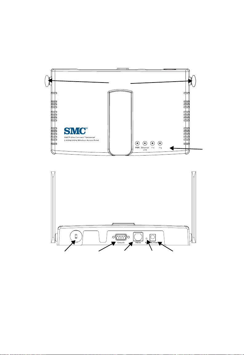
Hardware Description
Front Pa nel
Antennas
Rear Panel
Hardware Description
Indicator
Panel
Security Slot
Console
Port
RJ-45 Port,
PoE Connector
Reset
Button
5 VDC
Power Socket
1-3
Page 26
Introduction
Component Description
Antennas
The access point includes two antennas for wireless
communications. The signal transmitted from both antennas is
identical, but only the best signal received on one of the antennas
is used. The antennas transmit the outgoing signal along a
horizontal plane perpendicular to the antenna (in the shape of a
toroidal sphere, or a donut). The antennas should therefore be
adjusted to different angles to provide better coverage. For further
information, see “Positioning the Antennas” on page 2-2.
Note: You can install an optional SMC 2.4 GHz high-gain antenna for
802.11b and/or 802.11g client s in the socket on the rig ht antenna.
Also, remember t o order the j umper cabl e (
to connect an external antenna to the access point. See “Radio
Settings (802.11g)” on page 5-44 for information on selecting the
antenna in use.
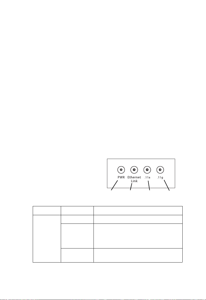
LED Indicators
The access point includes
four status LED indicators, as
described in the following
figure and table.
Power
SMC2555W-JMPRCBL)
Ethernet
Link/Activity
802.11a
Wireless
Link/Activity
802.11b/g
Wireless
Link/Activity
1-4
LED Status Description
PWR On Indicates that power is being supplied.
Flashing Indicates -
• running a self-test
• loading software program
Flashing
Indicates system err ors
(Prolonged)
Page 27

Hardware Description
LED Status Description
Ethernet
Link
.11a On Indicates a valid 802.11a wireless link.
On Indicates a valid 10/100 Mbps Ethernet
cable link.
Flashing Indicates that the access point is
transmitting or receiving data on a
10/100 Mbps Ethernet LAN. Flashing
rate is proportional to your network
activity.
Very Slow
Flashing
Slow
Flashing
Fast
Flashing
.11g On Indicates a valid 802.11g or 802.11b
Very Slow
Flashing
Slow
Flashing
Fast
Flashing
Searching for network association.
Associated with network but no activity.
Indicates that the access point is
transmitting or receiving data through
wireless links. Flashing rate is
proportional to network act ivity .
wireless link.
Searching for network association.
Associated with network but no activity.
Indicates that the access point is
transmitting or receiving data through
wireless links. Flashing rate is
proportional to network act ivity .
Security Slot
The access point includes a Kensington security slot on the rear
panel. You can prevent unauthorized removal of the access point
by wrapping the Kensington security cable (not provided) around
an unmovable object, inserting the lock into the slot, and turning
the key.
1-5
Page 28

Introduction
Console Port
This port is used to connect a console device to the access point
through a serial cable. This connection is described under
“Console Port Pin Assignments” on page B-4. The console device
can be a PC or workstation running a VT-100 terminal emulator,
or a VT-100 terminal.
Ethernet Port
The access point has one 10BASE-T/100BASE-TX RJ-45 port
that can be attached directly to 10BASE-T/100BASE-TX LAN
segments. These segments must conform to the IEEE 802.3 or
802.3u specificatio ns.
This port uses an MDI (i.e., internal straight-through) pin
configuration. You can therefore use straight-through twisted-pair
cable to connect this port to most network interconnection
devices such as a switch or router that provide MDI-X ports.
However, when connecting the access point to a workstation or
other device that does not have MDI-X ports, you must use
crossover twisted-pair cable.
The access point appears as an Ethernet node and performs a
bridging function by moving packets from the wired LAN to
remote workstations on the wireless infrastructure.
Note: The RJ-45 port also supports Power over Ethernet (PoE) based
on the IEEE 802.3af standard. Refer to the description for the
“Power Connector” for information on supplying power to the
access point’s network port from a network device, such as a
switch, that provides Power over Ethernet (PoE).
Reset Button
This button is used to reset the access point or restore the factory
default configuration. If you hold down the button for less than 5
seconds, the access point will perform a hardware reset. If you
hold down the button for 5 seconds or more, any configuration
1-6
Page 29

Features and Benefits
changes you may have made are removed, and the factory
default configuration is restored to the access point.
Power Connector
The access point does not have a power switch. It is powered on
when connected to the AC power adapter, and the power adapter
is connected to a power source. The access point automatically
adjusts to any voltage between 100-240 volts at 50 or 60 Hz. No
voltage range settings are required.
The access point may also receive Power over Ethernet (PoE)
from a switch or other network device that supplies power over
the network cable based on the IEEE 802.3af standard.
Note that if the access point is connected to a PoE source device
and also connected to a local power source through the AC
power adapter, PoE will be disabled.
Features and Benefits
• Local network connection via 10/100 Mbps Ethernet ports or
54 Mbps wireless interface (supporting up to 64 mobile users)
• IEEE 802.11a, 802.11b, and 802.11g compliant
• Advanced security through 64/128/152-bit Wired Equivalent
Protection (WEP) encryption, IEEE 802.1x port
authentication, Wi-Fi Protected Access (WPA), SSID
broadcast disable, remote authentication via RADIUS server,
and MAC address filtering features to protect your sensitive
data and authenticate only authorized users to your network
• Pr ovides seaml es s roami ng with in the IEE E 802. 11a ,
802.11b, and 802.11g WLAN environment
1-7
Page 30

Introduction
• Scans all available channels and selects the best channel for
each client based on the signal-to-noise ratio
Applications
The Wireless products offer a high speed, reliable, cost-effective
solution for 10/100 Mbps wireless Ethernet client access to the
network in applications such as:
• Remote access to corporate network information
E-mail, file transfer, and terminal emulation.
• Difficult-to-wire environments
Historical or old buildings, asbestos installations, and open
areas where wiring is difficult to employ.
• Frequently changing environments
Retailers, manufacturers, and banks that frequently
rearrange the workplace or change location.
• Temporary LANs for special projects or peak times
Trade shows, exhibitions and constr uc tio n site s which nee d
temporary setup for a short time period. Retailers, airline and
shipping companies that need additional workstations for a
peak period. Auditors who require workgroups at customer
sites.
• Access to databases for mobile workers
Doctors, nurses, retailers, or white-collar workers who need
access to databases while being mobile in a hospital, retail
store, or an office campus.
1-8
Page 31

System Defaults
System Defaults
The following table lists some of the access point’s basic system
defaults. To reset the access point defaults, use the CLI
command “reset configuration” from the Exec level prompt.
Feature Parameter Default
Identification System Name Enterprise AP
Administration User Name admin
Password smcadmin
General HTTP Server Enabled
HTTP Server Port 80
TCP/IP DHCP Enabled
IP Address 192.168.2.2
Subnet Mask 255.255.255.0
Default Gateway 0.0.0.0
Primary DN S IP 0.0.0.0
Secondary DNS IP 0.0.0.0
RADIUS
(Primary and
Secondary)
IP Address 0.0.0.0
Port 1812
Key DEFAULT
Timeout 5 seconds
Retransmit attempts 3
1-9
Page 32

Introduction
Feature Parameter Default
MAC
Authentication
802.1x
Authentication
VLAN Native VLAN ID 1
Filter Control Local Bridge Disabled
SNMP Status Enabled
MAC Local MAC
Authentication
Session Timeout
Local MAC
System Default
Local MAC
Permission
Status Disabled
Broadcast Key
Refresh
Session Key Refresh 0 minutes (disabled)
Reauthentication
Refresh Rate
VLAN Tag Support Disabled
Local Management Disabled
Ethernet Type Disabled
Location null
Contact Contact
Community
(Read Only)
Community
(Read/Write)
Traps Enabled
Trap Destination
IP Address
Trap Destination
Community Name
0 seconds (disabled)
Allowed
Allowed
0 minutes (disabled)
0 seconds (disabled)
Public
Private
null
Public
1-10
Page 33

Feature Parameter Default
System
Logging
Ethernet
Interface
Syslog Disabled
Logging Host Disabled
Logging Console Disabled
IP Address / Host
Name
Logging Level Informational
Logging Facility Type 16
Speed and Duplex Auto
0.0.0.0
System Defaults
1-11
Page 34

Introduction
Feature Parameter Default
Wireless
Interface
802.11a
Wireless
Security
802.11a
IAPP Enabled
SSID SMC
Status Enabled
Turbo Mode Disabled
Radio Channel Default to first channel
Auto Channel Select Enabled
SSID Broadcast Enabled
Transmit Power Full
Maximum Data Rate 54 Mbps
Beacon Interval 100 TUs
Data Beacon Rate
(DTIM Interval)
RTS Threshold 2347 bytes
Authentication Type Open System
WEP Encryption Disabled
WEP Key Length 128 bits
WEP Key Type Hexadecimal
WEP Transmit Key
Number
WEP Keys null
WPA Configuration
Mode
WPA Key
Management
Multicast Cipher WEP
2 beacons
1
All clients
WPA authentication
over 802.1x
1-12
Page 35

Feature Parameter Default
Wireless
Interface
802.11b/g
Wireless
Security
802.11b/g
IAPP Enabled
SSID SMC
Status Enabled
Channel Default to first channel
Auto Channel Select Enabled
SSID Broadcast Enabled
Antenna Mode Diversity
Radio Mode 11b and 11g mixed mode
Transmit Power Full
Maximum Data Rate 54 Mbps
Beacon Interval 100 TUs
Data Beacon Rate
(DTIM Interval)
RTS Threshold 2347 bytes
Authentication Type Open System
WEP Encryption Disabled
WEP Key Length 128 bits
WEP Key Type Hexadecimal
WEP Transmit Key
Number
WEP Keys null
WPA Configuration
Mode
WPA Key
Management
Multicast Cipher WEP
2 beacons
1
All clients
WPA authentication
over 802.1x
System Defaults
1-13
Page 36

Introduction
1-14
Page 37

Chapter 2
Hardware Installation
1. Select a Site – Choose a proper place for the access point. In
general, the best location is at the center of your wireless
coverage area, within line of sight of all wireless devices. Try
to place the access point in a position that can best cover its
Basic Service Set. (Refer to “Infrastructure Wireless LAN” on
page 3-3.) Normally, the higher you place the access point,
the better the performance.
2. Mount the Access Point – The access point can be mounted
on any horizontal surface or wall.
Mounting on a horizontal surface – To keep the access point
from sliding on the surface, attach the four rubber feet
provided in the accessory kit to the embossed circles on the
bottom of the access point.
Mounting on a wall – The access point should be mounted
only to a wall or wood surface that is at least 1/2-inch plywood
or its equivalent. Mark the position of the mounting screws
(included) on the wall. Set the 5/8-inch number 12 wood
screws into the wall, leaving about 3 mm (0.12 in.) clearance
from the wall. And then slide the access point down onto the
screws.
3. Lock the Access Point in Place – To prevent unauthorized
removal of the access point, you can use a Kensington Slim
MicroSaver security cable (not included) to attach the access
point to a fixed object.
4. Connect the Power Cord – Connect the power adapter to
the access point, and the power cord to an AC power outlet.
2-1
Page 38

Hardware Installation
Otherwise, the access point can derive its operating power
directly from the RJ-45 port when connected to a device that
provides IEEE 802.3af compliant Power over Ethernet (PoE).
Note: If the access point is connected to both a PoE source device
and an AC power source, PoE will be disabled.
Warning: Use ONLY the power adapter supplied with this access
point. Otherwise, the product may be damaged.
5. Observe the Self Test – When you power on the access
point, verify that the PWR indicator stops flashing and
remains on, and that the other indicators start functioning as
described under “LED Indicators” on page 1-4.
If the PWR LED does not stop flashing, the self test has not
completed correctly. Refer to “Troubleshooting” on page A-1.
6. Connect the Ethernet Cable – The access point can be
wired to a 10/100 Mbps Ethernet through a network device
such as a hub or a switch. Connect your network to the RJ-45
port on the back panel with category 3, 4, or 5 UTP Ethernet
cable. When the access point and the connected device are
powered on, the Ethernet Link LED should light indicating a
valid network connection.
Note: The RJ-45 port on the access point uses an MDI pin
configuration, so you must use straight-through cable for
network connections to hubs or switches that only have
MDI-X ports, and crossover cable for network connections to
PCs, servers or other end nodes that only have MDI ports.
However, if the device to which you are connecting supports
auto-MDI/MDI-X operation, you can use either
straight-through or crossover cable.
7. Position the Antennas – The antennas emit signals along a
plane perpendic ul ar to the antenna (wi th the propag ati on
pattern shaped as a toroidal sphere as shown to the left), and
thus provide more effective coverage when positioned along
different axes. For example, you might position the antennas
around 45 to 90 degrees from each other.
2-2
Page 39

Hardware Installation
The access point also compares the strength of an incoming
signal on both antennas, and uses the antenna receiving the
stronger signal to communicate with a wireless client.
8. Connect the Console Port – Connect the console cable
(included) to the RS-232 console port for accessing the
command-line interface. You can manage the access point
using the console port (Chapter 6), the web interface
(Chapter 5), or SNMP management software such as SMC’s
EliteView.
2-3
Page 40

Hardware Installation
2-4
Page 41

Chapter 3
Network Configuration
The wireless solution supports a stand-alone wireless network
configuration as well as an integrated configuration with
10/100 Mbps Ethernet LANs.
Wireless network cards, adapters, and access points can be
configured as:
• Ad hoc for departmental, SOHO, or enterprise LANs
• Infrastructure for wireless LANs
• Infrastructure wireless LAN for roaming wireless PCs
The 802.11b and 802.11g frequency band which operates at
2.4 GHz can easily encounter interference from other 2.4 GHz
devices, such as other 802.11b or g wireless devices, cordless
phones and microwave ovens. If you experience poor wireless
LAN performance, try the following measures:
• Limit any possible sources of radio interference within the
service area
• Increase the distance between neighboring access points to
reduce interference
• Increase the channel separation of neighboring access points
(e.g., up to 3 channels of separation for 802.11b, up to 4
channels for 802.11a, or up to 5 channels for 802.11g)
3-1
Page 42
Network Configuration
Network Topologies
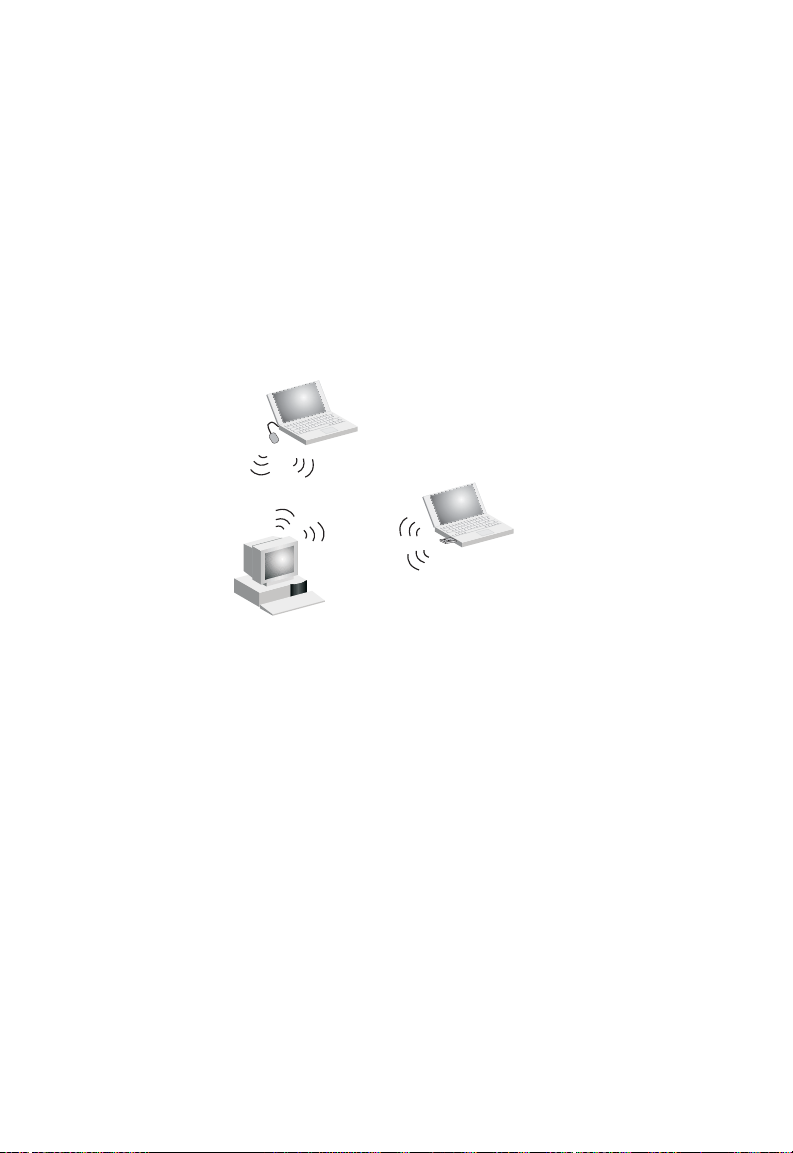
Ad Hoc Wireless LAN (no AP or Bridge)
An ad hoc wireless LAN consists of a group of computers, each
equipped with a wireless adapter, connected via radio signals as
an independent wireless LAN. Computers in a specific ad hoc
wireless LAN must therefore be configured to the same radio
channel.
Ad Hoc Wireless LAN
Notebook with
Wireless USB Adapter
Notebook with
Wireless PC Card
PC with Wireless
PCI Adapter
3-2
Page 43

Network Topologies
Infrastructure Wireless LAN
The access point also provides access to a wired LAN for
wireless w ork stations. An integrated wired/wireless LAN is called
an Infrastructure configuration. A Basic Service Set (BSS)
consists of a group of wireless PC users, and an access point
that is directly connected to the wired LAN. Each wireless PC in
this BSS can talk to any computer in its wireless group via a radio
link, or access other computers or network resources in the wired
LAN infrastructure via the access point.
The infrastructure configuration not only extends the accessibility
of wireless PCs to the wired LAN, but also increases the effective
wireless transmission range for wireless PCs by passing their
signal through one or more access points.
A wireless infrastructure can be used for access to a central
database, or for connection between mobile workers, as shown in
the following figure.
Wired LAN Extension
to Wireless Adapters
File
Server
Desktop PC
Switch
Notebook with Wireless
PC Card Adapter
Access Point
PC with Wireless
PCI Adapter
3-3
Page 44

Network Configuration
Infrastructure Wireless LAN for Roaming Wireless PCs
The Basic Service Set (BSS) defines the communications domain
for each access point and its associated wireless clients. The
BSS ID is a 48-bit binary number based on the access point’s
wireless MAC address, and is set automatically and transparently
as clients associate with the access point. The BSS ID is used in
frames sent between the access point and its clients to identify
traffic in the service area.
The BSS ID is only set by the access point, never by its clients.
The clients only need to set the Service Set Identifier (SSID) that
identifies the service set provided by one or more access points.
The SSID can be manually configured by the clients, can be
detected in an access point’s beacon, or can be obtained by
querying for the identity of the nearest access point. For clients
that do not need to roam, set the SSID for the wireless card to
that used by the access point to which you want to connect.
3-4
Page 45
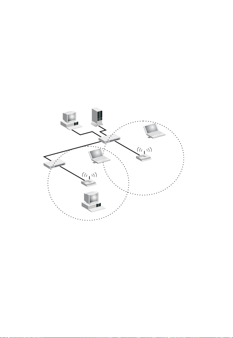
Network Topologies
A wireless infrastructure can also support roaming for mobile
workers. More than one access point can be configured to create
an Extended Service Set (ESS). By placing the access points so
that a continuous coverage area is created, wireless users within
this ESS can roam freely. All SMC wireless network card
adapters and SMC2555W-AG wireless access points within a
specific ESS must be configured with the same SSID.
File
Server
Desktop PC
Switch
Notebook with Wireless
PC Card Adapter
Switch
PC with Wireless
PCI Adapter
Access Point
Notebook with Wireless
PC Card Adapter
<BSS1>
Access Point
<ESS>
Seamless Roaming
<BSS2>
3-5
Page 46

Network Configuration
3-6
Page 47

Chapter 4
Initial Configuration
The EliteConnect Universal 2.4GHz/5GHz Wireless Access
Point SMC2555W-AG offers a variety of management options,
including a web-based interface, a direct connection to the
console port, or using SNMP software such as SMC’s EliteView.
The initial configuration steps can be made through the web
browser interface using the Setup Wizard (page 4-4). The access
point requests an IP address via DHCP by default. If no response
is received from a DHCP server, then the access point uses the
default address 192.168.2.2. If this address is not compatible with
your network, you can first use the command line interface (CLI)
as described below to configure a valid address.
Note: Units sold in countries outside the United States are not
configured with a specific country code. You must use the CLI to
set the country code and enable wireless operation (page 4-4).
Initial Setup through the CLI
Required Connections
The SMC2555W-AG provides an RS-232 serial port that enables
a connection to a PC or terminal for monitoring and configuration.
Attach a VT100-compatible terminal, or a PC running a terminal
emulation program to the access point. You can use the console
cable provided with this package, or use a null-modem cable that
complies with the wiring assignments shown on page B-4.
4-1
Page 48

Initial Configuration
To connect to the console port, complete the following steps:
1. Connect the console cable to the serial port on a terminal, or
a PC running terminal emulation software, and tighten the
captive retaining screws on the DB-9 connector.
2. Connect the other end of the cable to the RS-232 serial port
on the access point.
3. Make sure the terminal emulation software is set as follows:
• Select the appropriate serial port (COM port 1 or 2).
• Set the data rate to 9600 baud.
• Set the data format to 8 data bits, 1 stop bit, and no parity.
• Set flow control to none.
• Set the emulation mode to VT100.
• When using HyperTerminal, select Terminal keys, not
Windows keys.
Note: When using HyperTerminal with Microsoft
sure that you have Windows 2000 Service Pack 2 or later installed.
Windows 2000 Service Pack 2 fixes the problem of arrow keys not
functioning in HyperTerminal’s VT100 emulation. See
www.microsoft.com for information on Windows 2000 service packs.
®
Windows® 2000, make
4. Once you have set up the terminal correctly, press the [Enter]
key to initiate the console connection. The console login
screen will be displayed.
For a description of how to use the CLI, see “Using the Command
Line Interface” on page 6-1. For a list of all the CLI commands
and detailed information on using the CLI, refer to “Command
Groups” on page 6-10.
4-2
Page 49

Initial Setup through the CLI
Initial Configuration Steps
Logging In – Enter “admin” for the user name and “smcadmin”
for the password. The CLI prompt appears displaying the access
point’s model number.
Username: admin
Password:
SMC Enterprise AP#
Setting the IP Address – By default, the access point is
configured to obtain IP address settings from a DHCP server. You
may also use the command line interface (CLI) to assign an IP
address that is compatible with your network.
Type “configure” to enter configuration mode, then type “interface
ethernet” to access the Ethernet interface-configuration mode.
SMC Enterprise AP#configure
SMC Enterprise AP(config)#interface ethernet
SMC Enterprise AP(config-if)#
First type “no ip dhcp” to disable DHCP client mode. Then type “ip
address ip-address netmask gateway,” where “ip-address” is the
access point’s IP address, “netmask” is the network mask for the
network, and “gateway” is the default gateway router. Check with
your system administrator to obtain an IP address that is
compatible with your network.
SMC Enterprise AP(if-ethernet)#no ip dhcp
SMC Enterprise AP(if-ethernet)#ip address 192.168.2.2
255.255.255.0 192.168.2.254
SMC Enterprise AP(if-ethernet)#
After configuring the access point’s IP parameters, you can
access the management interface from anywhere within the
attached network. The command line interface can also be
4-3
Page 50

Initial Configuration
accessed using Telnet from any computer attached to the
network.
Setting the Country Code – Units sold in the United States are
configured by default to use only radio channels 1-11 as defined
by FCC regulations. Units sold in other countries are configured
by default without a country code (i.e., 99). You must use the CLI
to set the country code. Setting the country code restricts
operation of the access point to the radio channels permitted for
wireless networks in the specified country.
Type “exit” to leave configuration mode. Then type “country ?” to
display the list of countries. Select the code for your country, and
enter the country command again, following by your country code
(e.g., IE for Ireland).
SMC Enterprise AP#country ie
SMC Enterprise AP#
Using the Web-based Management
Setup Wizard
There are only a few basic steps you need to complete to connect
the SMC2555W-AG to your corporate network, and provide
network access to wireless clients. The Setup Wizard takes you
through configuration procedures for the wireless Service Set
Identifier, the radio channel selection, and IP configuration.
The SMC2555W-AG can be managed by any computer using a
web browser. Enter the default IP address: http://192.168.2.2
4-4
Page 51
Using the Web-based Management Setup Wizard
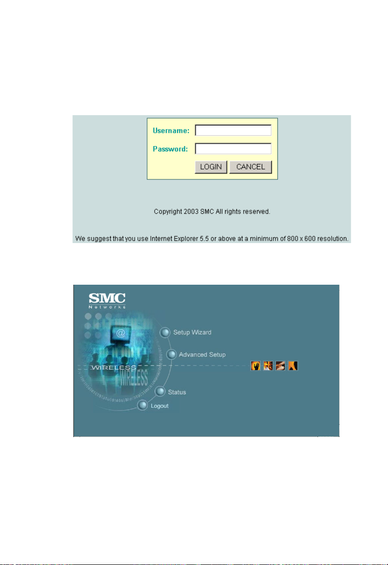
Logging In – Enter the username “admin,” the password
“smcadmin,” and click LOGIN. For information on configuring a
user name and password, refer to page 5-27.
The home page displays the Main Menu.
4-5
Page 52

Initial Configuration
Launching the Setup Wizard – To perform initial configuration,
click Setup Wizard on the home page, then click on the [Next]
button to start the process.
1. Service Set ID – Enter the service set identifier in the SSID
box which all wireless clients must use to associate with the
access point. The SSID is case sensitive and can consist of
up to 32 alphanumeric characters. (Default: SMC)
4-6
Page 53

Using the Web-based Management Setup Wizard
2. Radio Channel – You must enable radio communications for
802.11a and 802.11b/g, and set the operating radio channel.
• 802.11a
Turbo Mode – If you select Enable, the
access point will operate in turbo mode with
a data rate of up to 108 Mbps. Normal mode
support 13 channels, Turbo mode supports
only 5 channels. (Default: Disable)
802.11a Radio Channel – Set the operating
radio channel number. (Default: 60ch,
5.300 GHz)
Auto Channel Select – Select Enable for automatic radio
channel detection. (Default: Enable)
4-7
Page 54

Initial Configuration
• 802.11b/g
802.11g Radio Channel: Set the operating radio
channel number. (Range: 1-11; Default: 11)
Note: Available channel settings ar e limited by local
regulations which determine which channels are
available. (See “Maximum Channels” on page C-1.)
3. IP Configuration – Either enable or disable Dynamic
Host Configuration Protocol (DHCP) for automatic IP
configuration. If you disable DHCP, then manually enter
the IP address and subnet mask. If a management
station exists on another network segment, then you
must enter the IP address for a gateway that can route traffic
between these segments. Then enter the IP address for the
primary and secondary Domain Name Servers (DNS) servers
to be used for host-name to IP address resolution.
4-8
Page 55

Using the Web-based Management Setup Wizard
DHCP Client – With DHCP Client enabled, the IP address,
subnet mask and default gateway can be dynamically
assigned to the access point by the network DHCP server.
(Default: Enable)
Note: If there is no DHCP server on your network, then the access
point will automatically start up with its default IP address,
192.168.2.2.
4. Click Finish.
5. Click the OK button to restart the access point.
4-9
Page 56

Initial Configuration
4-10
Page 57

Chapter 5
System Configuration
Before continuing with advanced configuration, first complete the
initial configuration steps described in Chapter 4 to set up an IP
address for the SMC2555W-AG.
The SMC2555W-AG can be managed by any computer using a
web browser. Enter the default IP address: http://192.168.2.2
To log into the SMC2555W-AG, enter the default user name
“admin” and password “smcadmin.” When the home page
displays, click on Advanced Setup. The following page will
display.
5-1
Page 58

System Configuration
The information in this chapter is organized to reflect the structure
of the web screens for easy reference. However, we recommend
that you configure a user name and password as the first step
under advanced configuration to control management access to
this device (page 5- 27 ).
Advanced Configuration
The Advanced Configuration pages include the following options.
Menu Description Page
System Configures basic administrative and client
Identification Specifies the host name and Service Set
TCP / IP Settings Configures the IP address, subnet mask,
Radius Configures the RADIUS server for wireless
Authentication Configures 802.1x cl ient authentication, wi th
Filter Control Filters communications between wirel es s
SNMP Controls access to this access point from
Administration Configures user name and password for
System Log Controls logging of error m essages; sets the
access
Identifier (SSID)
gateway, and domain name servers
client authenticati on
an option for MAC address authentication
clients, access to the managemen t interface
from wireless clients, and traffic matching
specific Ethernet protocol types
management stations using SNMP, as well
as the hosts that will receive trap messages
management
from local file, FTP or TFT P server;
configuration settings to factory defaults;
and resets the access point
system clock via SNTP server or manual
configuration
access; upgrades software
resets
5-4
5-4
5-6
5-9
5-12
5-19
5-24
5-27
5-33
5-2
Page 59

Advanced Configuration
Menu Description Page
Radio Interface 1 Configures the IEEE 802.11a interface 5-38
Radio Settings Configures radio signal parameters, such as
radio channel, transmission rate, and
beacon settings
Security Configures data encryption with Wired
Equivalent Protection (WEP) or Wi-Fi
Protected Access (WPA)
Radio Interface 2 Configures the IEEE 802.11b/g interface 5-38
Radio Settings Configures radio signal parameters, such as
radio channel, transmission rate, and
beacon settings
Security Configures data encryption with Wired
Equivalent Protection (WEP) or Wi-Fi
Protected Access (WPA)
5-39
5-48
5-44
5-48
5-3
Page 60
System Configuration
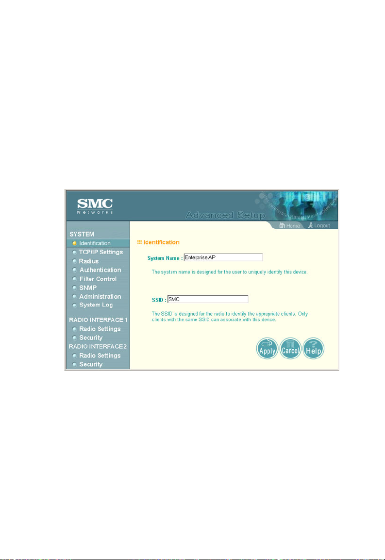
System Identification
The system information parameters for the SMC2555W-AG can
be left at their default settings. However, modifying these
parameters can help you to more easily distinguish different
devices in your network.
You should set a Service Set Identification (SSID) to identify the
wireless network service provided by the SMC2555W-AG. Only
clients with the same SSID can associate with the access point.
System Name – An alias for the access point, enabling the device
to be uniquely identified on the network. (Default: Enterprise AP;
Range: 1-22 characters)
SSID – The name of the basic service set provided by the access
point. Clients that want to connect to the network through the
access point must set their SSID to the same as that of the
access point. (Default: SMC; Range: 1-32 characters)
5-4
Page 61

Advanced Configuration
CLI Commands for System Identification – Enter the global
configuration mode, and use the system name command to
specify a new system name. Enter the wireless configuration
mode (either 11a or 11g), and use the ssid command to set the
service set identifier. Then return to the Exec mode, and use the
show system command to display the changes to the system
identification settings.
SMC AP#configure 6-11
SMC-AP(config)#system name R&D 6-20
SMC-AP(config)#interface wireless a 6-68
SMC-AP(if-wireless a)#ssid r&d 6-79
SMC-AP(if-wireless a)#end 6-12
SMC-AP#show system 6-33
System Information
===================================================
Serial Number : A324003220
System Up time : 0 days, 0 hours, 32 minutes, 51 seconds
System Name : r&d
System Location :
System Contact : Contact
System Country Code : US - UNITED STATES
MAC Address : 00-30-F1-91-91-5B
IP Address : 192.168.2.51
Subnet Mask : 255.255.255.0
Default Gateway : 192.168.2.250
VLAN State : DISABLED
Native VLAN ID : 1
IAPP State : ENABLED
DHCP Client : ENABLED
HTTP Server : ENABLED
HTTP Server Port : 80
Slot Status : Dual band(a/g)
Software Version : v2.0.13
===================================================
SMC-AP#
5-5
Page 62

System Configuration
TCP / IP Settings
Configuring the SMC2555W-AG with an IP address expands your
ability to manage the access point. A number of access point
features depend on IP addressing to operate.
Note: You can use the web browser interface to access IP addressing
only if the access point already has an IP address that is
reachable through your network.
By default, the SMC2555W-AG will be automatically configured
with IP settings from a Dynamic Host Configuration Protocol
(DHCP) server. However, if you are not using a DHCP server to
configure IP addressing, use the CLI to manually configure the
initial IP values (page 4-3). After you have network access to the
access point, you can use the web browser interface to modify
the initial IP configuration, if needed.
Note: If there is no DHCP server on your network, or DHCP fails, the
access point will automat ically start up w ith a default IP address of
192.168.2.2.
5-6
Page 63

Advanced Configuration
DHCP Client (Enable) – Select this option to obtain the IP
settings for the access point from a DHCP (Dynamic Host
Configuration Protocol) server. The IP address, subnet mask,
default gateway, and Domain Name Server (DNS) address are
dynamically assigned to the access point by the network DHCP
server. (Default: Enable)
DHCP Client (Disable) – Select this option to manually configure
a static address for the access point.
• IP Address: The IP address of the access point. Valid IP
addresses consist of four decimal numbers, 0 to 255,
separated by periods.
• Subnet Mask: The mask that identifies the host address bits
used for routing to specific subnets.
• Default Gateway: The default gatewa y is the IP address of the
router for the access point, which is used if the requested
destination address is not on the local subnet.
If you have management stations, DNS, RADIUS, or other
network servers located on another subnet, type the IP
address of the default gateway router in the text field provided.
Otherwise, leave the address as all zeros (0.0.0.0).
• Primary and Secondary DNS Address: The IP address of
Domain Name Servers on the network. A DNS maps
numerical IP addresses to domain names and can be used to
identify network hosts by familiar names instead of the IP
addresses.
If you have one or more DNS servers located on the local
network, type the IP addresses in the text fields provided.
Otherwise, leave the addresses as all zeros (0.0.0.0).
5-7
Page 64

System Configuration
CLI Commands for TCP/IP Settings – From the global
configuration mode, enter the interface configuration mode with
the interface ethernet command. Use the ip dhcp command to
enable the DHCP client, or no ip dhcp to disable it. To manually
configure an address, specify the new IP address, subnet mask,
and default gateway using the ip address command. To spec ify
DNS server addresses use the dns server command. Then use
the show interface ethernet command from the Exec mode to
display the current IP settings.
SMC-AP(config)#interface ethernet 6-68
Enter Ethernet configuration commands, one per line.
SMC-AP(if-ethernet)#no ip dhcp 6-71
SMC-AP(if-ethernet)#ip address 192.168.1.2
255.255.255.0 192.168.1.253 6-69
SMC-AP(if-ethernet)#dns primary-server 192.168.1.55 6-68
SMC-AP(if-ethernet)#dns secondary-server 10.1.0.55 6-68
SMC-AP(config)#end 6-12
SMC-AP#show interface ethernet 6-72
Ethernet Interface Information
========================================
IP Address : 192.168.1.2
Subnet Mask : 255.255.255.0
Default Gateway : 192.168.1.253
Primary DNS : 192.168.1.55
Secondary DNS : 10.1.0.55
Admin status : Up
Operational status : Up
========================================
SMC-AP#
5-8
Page 65

Advanced Configuration
Radius
Remote Authentication Dial-in User Service (RADIUS) is an
authentication protocol that uses software running on a central
server to control access to RADIUS-aware devices on the
network. An authentication server contains a database of user
credentials for each user that requires access to the network.
A primary RADIUS server must be specified for the
SMC2555W-AG to implement IEEE 802.1x network access
control and Wi-Fi Protected Access (WPA) wireless security. A
secondary RADIUS server may also be specified as a backup
should the primary server fail or become inaccessible.
Note: This guide assumes that you have already configured RADIUS
server(s) to support the access point. Configuration of RADIUS
server software is beyond the scope of this guide, refer to the
documentation provided with the RADIUS server software.
5-9
Page 66

System Configuration
Primary Radius Server Setup – Configure the following settings
to use RADIUS authentication on the access point.
• IP Address: Specifies the IP address of the RADIUS server.
• Port: The UDP port number used by the RADIUS server for
authentication messages. (Ran ge: 1024 -6553 5;
Default: 1812)
• Key: A shared text string used to encrypt messages between
the access point and the RADIUS server. Be sure that the
same text string is specified on the RADIUS server. Do not
use blank spaces in the string. (Maximum length: 255
characters)
• Timeout: Number of seconds the access point waits for a reply
from the RADIUS server before resending a request.
(Range: 1-60 seconds; Default: 5)
• Retransmit attempts: The number of times the access point
tries to resend a request to the RADIUS server before
authentication fails. (Range: 1-30; Default: 3)
Note: For the Timeout and Retransmit attempts fields, accept the
default values unless you experi ence problem s connecting to the
RADIUS server over the network.
Secondary Radius Server Setup – Configure a secondary
RADIUS server to provide a backup in case the primary server
fails. The access point uses the secondary server if the primary
server fails or becomes inaccessible. Once the access point
switches over to the secondary server, it periodically attempts to
establish communication again with primary server. If
communication with the primary server is re-established, the
secondary server reverts to a backup role.
5-10
Page 67

Advanced Configuration
CLI Commands for RADIUS – From the global configuration
mode, use the radius-server address command to specify the
address of the primary or secondary RADIUS servers. (The
following example configures the settings for the primary RADIUS
server.) Configure the other parameters for the RADIUS server.
Then use the show show radius command from the Exec mode
to display the current settings for the primary and secondary
RADIUS servers.
SMC-AP(config)#radius-server address 192.168.1.25 6-46
SMC-AP(config)#radius-server port 181 6-46
SMC-AP(config)#radius-server key green 6-47
SMC-AP(config)#radius-server timeout 10 6-48
SMC-AP(config)#radius-server retransmit 5 6-47
SMC-AP(config)#exit
SMC-AP#show radius 6-49
Radius Server Information
========================================
IP : 192.168.1.25
Port : 181
Key : *****
Retransmit : 5
Timeout : 10
========================================
Radius Secondary Server Information
========================================
IP : 0.0.0.0
Port : 1812
Key : *****
Retransmit : 3
Timeout : 5
========================================
SMC-AP#
5-11
Page 68

System Configuration
Authentication
Wireless clients can be authenticated for network access by
checking their MAC address against the local database
configured on the access point, or by using the IEEE 802.1x
network access authentication protocol to look up their MAC
addresses on a RADIUS server. The 802.1x protocol can also be
configured to check other user credentials such as a user name
and password.
5-12
Page 69

Advanced Configuration
MAC Authentication – You can configure a list of the MAC
addresses for wireless clients that are authorized to access the
network. This provides a basic level of authentication for wireless
clients attempting to gain access to the network. A database of
authorized MAC addresses can be stored locally on the
SMC2555W-AG or remotely on a central RADIUS server.
(Default: Local MAC)
• Local MAC: The MAC address of the associating station is
compared against the local database stored on the access
point. The Local MAC Authentication section enables the local
database to be set up.
• Radius MAC: The MAC address of the associating station is
sent to a configured RADIUS server for authentication. When
using a RADIUS authentication server for MAC address
authentication, the server must first be configured in the
Radius window (page 5-9).
• Disable: No checks are performed on an associating station’s
MAC address.
Local MAC Authentication – Configures th e local MAC
authentication database. The MAC database provides a
mechanism to take certain actions based on a wireless client’s
MAC address. The MAC list can be configured to allow or deny
network access to specific clients.
• System Default: Specifies a default action for all unknown
MAC addresses (that is, those not listed in the local MAC
database).
- Deny: Blocks access for all MAC addresses except those
listed in the local database as “Allow.”
- Allow: Permits access for all MAC addresses except
those listed in the local database as “Deny.”
5-13
Page 70

System Configuration
• MAC Authentication Settings: Enters specified MAC
addresses and permissions into the local MAC database.
- MAC Address: Physical address of a client. Enter six pairs
of hexadecimal digits separated by hyphens; for example,
00-90-D1-12-AB-89.
- Permission: Select Allow to permit access or Deny to
block access. If Delete is selected, the specified MAC
address entry is removed from the database.
- Update: Enters the specified MAC address and
permission setting into the local database.
• MAC Authentication T able: Displays current entries in the local
MAC database.
802.1x Setup – IEEE 802.1x is a standard framework for network
access control that uses a central RADIUS server for user
authentication. This control feature prevents unauthorized access
to the network by requiring an 802.1x client application to submit
user credentials for authentication. The 802.1x standard uses the
Extensible Authentication Protocol (EAP) to pass user credentials
(either digital certificates, user names and passwords, or other)
from the client to the RADIUS server. Client authentication is then
verified on the RADIUS server before the access point grants
client access to the network.
The 802.1x EAP packets are also used to pass dynamic unicast
session keys and static broadcast keys to wireless clients.
Session keys are unique to each client and are used to encrypt
and correlate traffic passing between a specific client and the
access point. You can also enable broadcast key rotation, so the
access point provides a dynamic broadcast key and changes it at
a specified interval.
You can enable 802.1x as optionally supported or as required to
enhance the security of the wireless network.
• Disable: The access point does not support 802.1x
authentication for any wireless client. After successful
5-14
Page 71

Advanced Configuration
wireless association with the access point, each client is
allowed to access the network.
• Supported: The access point supports 802.1x authentication
only for clients initiating the 802.1x authentication process
(i.e., the access point does not initiate 802.1x authentication).
For clients initiating 802.1x, only thos e succ es sfu ll y
authenticated are allowed to access the network. For those
clients not initiating 802.1x, access to the network is allowed
after successful wireless association with the access point.
• Required: The access point enforces 802.1x authentication for
all associated wireless clients. If 802.1x authentication is not
initiated by a client, the access point will initiate authentication.
Only those clients successfully authenticated with 802.1x are
allowed to access the network.
When 802.1x is enabled, the broadcast and session key rotation
intervals can also be configured.
• Broadcast Key Refresh Rate: Sets the interval at which the
broadcast keys are refreshed for stations using 802.1x
dynamic keying. (Range: 0-1440 minutes; Default: 0 means
disabled)
• Session Key Refresh Rate: The interval at which the access
point refreshes unicast session keys for associated clients.
(Range: 0-1440 minutes; Default: 0 means disabled)
• 802.1x Re-authentication Refresh Rate: The time period after
which a connected client must be re-authenticated. During the
re-authentication process of verifying the client’s credentials
on the RADIUS server, the client remains connected the
network. Only if re-authentication fails is network access
blocked. (Range: 0-65535 seconds; Default: 0 means
disabled)
5-15
Page 72

System Configuration
CLI Commands for Local MAC Authentication – Use the
mac-authentication serv er command from the global
configuration mode to enable local MAC authentication. Set the
default for MAC addresses not in the local table using the
address filter default command, then enter MAC addresses in
the local table using the address filter entry command. To
remove an entry from the table, use the address filter delete
command. To display the current settings, use the show
authentication command from the Exec mode.
SMC-AP(config)#mac-authentication server local 6-57
SMC-AP(config)#address filter default denied 6-54
SMC-AP(config)#address filter entry 00-70-50-cc-99-1a denied 6-55
SMC-AP(config)#address filter entry 00-70-50-cc-99-1b allowed
SMC-AP(config)#address filter entry 00-70-50-cc-99-1c allowed
SMC-AP(config )# address filter de let e 00 -70-50-cc-99- 1c 6-56
SMC-AP(config)#exit
SMC-AP#show authentication 6-59
Authenticatio n In formation
=========================================================
MAC Authenticat io n Server : LOCAL
MAC Auth Session Ti meo ut Value : 300 secs
802.1x : DISABLED
Broadcast Key Refresh Rate : 5 min
Session Key Refresh Rate : 5 min
802.1x Session Timeout Value : 300 secs
Address Filtering : DENIED
System Default : DE NY ad dresses not found in fil te r table.
Filter Table
MAC Address Status
----------------- ---------00-70-50-cc-99-1a DENIED
00-70-50-cc-99-1b ALLOWED
=========================================================
SMC-AP#
5-16
Page 73

Advanced Configuration
CLI Commands for RADIUS MAC Authentication – Use the
mac-authentication serv er command from the global
configuration mode to enable remote MAC authentication. Set the
timeout value for re-authentication using the mac-authentication
session-timeout command. Be sure to also configure
connection settings for the RADIUS server (not shown i n the
following example). To display the current settings, use the show
authentication command from the Exec mode.
SMC-AP(config)#mac-authentication server remote 6-57
SMC-AP(config)#mac-authentication session-timeout 300 6-58
SMC-AP(config)#exit
SMC-AP#show authentication 6-59
Authentication Information
=========================================================
MAC Authentication Server : REMOTE
MAC Auth Session Timeout Value : 300 secs
802.1x : DISABLED
Broadcast Key Refresh Rate : 5 min
Session Key Refresh Rate : 5 min
802.1x Session Timeout Value : 300 secs
Address Filtering : DENIED
System Default : DENY addresses not found in filter table.
Filter Table
MAC Address Status
----------------- ---------00-70-50-cc-99-1a DENIED
00-70-50-cc-99-1b ALLOWED
=========================================================
SMC-AP#
5-17
Page 74

System Configuration
CLI Commands for 802.1x Authentication – Use the 802.1x
supported command from the global configuration mode to
enable 802.1x authentication. Set the session and broadcast key
refresh rate, and the re-authentication timeout. To display the
current settings, use the show authentication command from
the Exec mode.
SMC-AP(config)#802.1x supported 6-51
SMC-AP(config)#802.1x broadcast-key-refresh-rate 5 6-52
SMC-AP(config)#802.1x session-key-refresh-rate 5 6-53
SMC-AP(config)#802.1x session-timeout 300 6-54
SMC-AP(config)#exit
SMC-AP#show authentication 6-59
Authentication Information
=========================================================
MAC Authentication Server : REMOTE
MAC Auth Session Timeout Value : 300 secs
802.1x : SUPPORTED
Broadcast Key Refresh Rate : 5 min
Session Key Refresh Rate : 5 min
802.1x Session Timeout Value : 300 secs
Address Filtering : DENIED
5-18
System Default : DENY addresses not found in filter table.
Filter Table
MAC Address Status
----------------- ---------00-70-50-cc-99-1a DENIED
00-70-50-cc-99-1b ALLOWED
=========================================================
SMC-AP#
Page 75

Advanced Configuration
Filter Control
The access point can employ VLAN ID and network traffic frame
filtering to control access to network resources and increase
security.
5-19
Page 76

System Configuration
Native VLAN ID – The VLAN ID assigned to wireless clients that
are not assigned to a specific VLAN by RADIUS server
configuration.
VLAN – Enables or disables VLAN tagging support on the
SMC2555W-AG. If enabled, the access point will tag traffic
passing from wireless clients to the wired network with the VLAN
ID associated with each client on the RADIUS server. Up to 64
VLAN IDs can be mapped to specific wireless clients, allowing
users to remain within the same VLAN as they move around a
campus site. This feature can also be used to control access to
network resources from wireless clients, thereby improving
security.
A VLAN ID (1-4095) is assigned to a client after successful
authentication using IEEE 802.1x and a central RADIUS server.
The user VLAN IDs must be configured on the RADIUS server for
each user authorized to access the network. If a user does not
have a configured VLAN ID, the access point assigns the user to
its own configured native VLAN ID.
When setting up VLAN IDs for each user on the RADIUS server,
be sure to use the RADIUS attributes and values as indicated in
the following table.
Number RADIUS Attribute Value
64 Tunnel-Type VLAN (13)
65 Tunnel-Medium-Type 802
81 Tunnel-Private-Group VLANID
(1 to 4095 in
hexadecimal)
Note: The specific configuration of RADIUS server software is beyond
the scope of this guide. Refer to the documentation provided with
the RADIUS server software.
5-20
Page 77

Advanced Configuration
When VLAN filtering is enabled, the access point must also have
802.1x authentication enabled and a RADIUS server configured.
Wireless clients must also support 802.1x client software to be
assigned to a specific VLAN.
When VLAN filtering is disabled, the access point ignores the
VLAN tags on any received frames.
Local Bridge Filter – Controls wireless-to-wireless
communications between clients through the SMC2555W-AG.
However, it does not affect communications between wireless
clients and the wired network.
• Disable: Allows wireless-to-wireless communications between
clients through the access point.
• Enable: Blocks wireless-to-wireless communications between
clients through the access point.
AP Management Filter – Controls management access to the
SMC2555W-AG from wireless clients. Management interfaces
include the web, Telnet, or SNMP.
• Disable: Allows management access from wireless clients.
• Enable: Blocks management access from wireless clients.
Ethernet Type Filt er – Controls checks on the Ethernet type of all
incoming and outgoing Ethernet packets against the protocol
filtering table.
• Disable: Access point does not filter Ethernet protocol types.
• Enable: Access point filters Ethernet protocol types based on
the configuration of protocol types in the filter table. If a
protocol has its status set to “ON, ” the protocol is filtered from
the access point.
5-21
Page 78

System Configuration
CLI Commands for VLAN Support – From the global
configuration mode use the native-vlanid command to set the
default VLAN ID for the Ethernet interface, then enable VLANs
using the vlan enable command. When you change the access
point’s VLAN support setting, you must reboot the access point to
implement the change. To view the current VLAN settings, use
the show system command.
SMC-AP(config)#native-vlanid 3 6-101
SMC-AP(config)#vlan enable 6-100
Reboot system now? <y/n>: y
SMC-AP#show system 6-33
System Information
===================================================
Serial Number : A324003220
System Up time : 0 days, 0 hours, 32 minutes, 51
seconds
System Name : r&d
System Location :
System Contact : Contact
System Country Code : US - UNITED STATES
MAC Address : 00-30-F1-91-91-5B
IP Address : 192.168.2.51
Subnet Mask : 255.255.255.0
Default Gateway : 192.168.2.250
VLAN State : DISABLED
Native VLAN ID : 3
IAPP State : ENABLED
DHCP Client : ENABLED
HTTP Server : ENABLED
HTTP Server Port : 80
Slot Status : Dual band(a/g)
Software Version : v2.0.13
===================================================
5-22
SMC-AP#
Page 79

Advanced Configuration
CLI Commands for Bridge Filtering – Use the filter local-bridge
command from the global configuration mode to prevent
wireless-to-wireless communications through the access point.
Use the filter ap-manage command to restrict management
access from wireless clients. To configure Ethernet protocol
filtering, use the filter ethe rne t- t ype enable command to enable
filtering and the filter ethernet-type protocol command to define
the protocols that you want to filter. To remove an entry from the
table, use the address filter delete command. To display the
current settings, use the show filters command from the Exec
mode.
SMC-AP(config)#filter local-bridge 6-60
SMC-AP(config)#filter ap-manage 6-61
SMC-AP(config)#filter ethernet-type enable 6-62
SMC-AP(config)#filter ethernet-type protocol ARP 6-63
SMC-AP(config)#exit
SMC-AP#show filters 6-64
Protocol Filter Information
=========================================================
Local Bridge :ENABLED
AP Management :ENABLED
Ethernet Type Filter :ENABLED
Enabled Protocol Filters
--------------------------------------------------------Protocol: ARP ISO: 0x0806
=========================================================
SMC-AP#
5-23
Page 80

System Configuration
SNMP
You can use a network management application such as SMC’s
EliteView (EliteView v6.11, available in Q4 of 2003) to manage
the SMC2555W-AG via the Simple Network Management
Protocol (SNMP) from a network management station. To
implement SNMP management, the SMC2555W-AG must have
an IP address and subnet mask, configured either manually or
dynamically. Once an IP address has been configured,
appropriate SNMP communities and trap receivers should be
configured.
Community names are used to control management access to
SNMP stations, as well as to authorize SNMP stations to receive
trap messages from the access point. To communicate with the
access point, a management station must first submit a valid
community name for authentication. You therefore need to assign
community names to specified users or user groups and set the
access level.
5-24
Page 81

Advanced Configuration
SNMP – Enables or disables SNMP management access and
also enables the access point to send SNMP traps (notifications).
SNMP management is enabled by default.
Location – A text string that describes the system location.
(Maximum length: 20 characters)
Contact – A text string that describes the system contact.
(Maximum length: 255 characters)
Community Name (Read Only) – Defines the SNMP community
access string that has read-only access. Authorized management
stations are only able to retrieve MIB objects. (Maximum length:
23 characters, case sensitive)
Community Name (Read/Write) – Defines the SNMP community
access string that has read/write access. Authorized
management stations are able to both retrieve and modify MIB
objects. (Maximum length: 23 characters, case sensitive)
Trap Destination IP Address – Specifies the recipient of SNMP
notifications. Enter the IP address or the host name.
(Host Name: 1 to 20 characters)
Trap Destination Community Name – The community string sent
with the notification operation. (Maximum length: 23 characters,
case sensitive)
5-25
Page 82

System Configuration
CLI Commands for SNMP – Use the snmp-server enable
server command from the global configuration mode. To set
read/write and read-only community names, use the
snmp-server community command. Use the snmp-server
location and snmp-server contact commands to indicate the
physical location of the access point and define a system contact.
The snmp-server host command defines a trap receiver host. T o
view the current SNMP settings, use the show snmp command.
SMC-AP(config)#snmp-server enable server 6-37
SMC-AP(config)#snmp-server community alpha rw 6-35
SMC-AP(config)#snmp-server community beta ro
SMC-AP(config)#snmp-server location WC-19 6-39
SMC-AP(config)#snmp-server contact Paul 6-36
SMC-AP(config)#snmp-server host 10.1.19.23 alpha 6-38
SMC-AP(config)#exit
SMC-AP#show snmp 6-40
SNMP Information
============================================
Service State : Enable
Community (ro) : ****
Community (rw) : *****
Location : WC-19
Contact : Paul
Traps : Enabled
Host Name/IP : 10.1.19.23
Trap Community : *****
=============================================
5-26
SMC-AP#
Page 83

Advanced Configuration
Administration
Changing the Password
Management access to the web and CLI interface on the
SMC2555W-AG is controlled through a single user name and
password. You can also gain additional access security by using
control filters. (See “Filter Control” on page 5-19.)
To protect access to the management interface, you need to
configure an Administrator’s user name and password as soon as
possible. If the user name and password are not configured, then
anyone having acce ss to the access point may be able to
compromise access point and network security.
Note: Pressing the Reset button on the back of the SMC2555W-AG for
more than five seconds rese ts the user name and pas sword to the
factory defaults. For this reason, we recommend that you protect
the access point from physical access by unauthorized persons.
Username – The name of the user. The default name is “admin.”
(Length: 3-16 characters, case sensitive.)
New Password – The password for management access.
(Length: 3-16 characters, case sensitive)
Confirm New Password – Enter the password again for
verification.
5-27
Page 84

System Configuration
CLI Commands for the User Name and Password – Use the
username and password commands from the CLI configuration
mode.
SMC-AP(config)#username bob 6-21
SMC-AP(config)#password smcadmin 6-22
SMC-AP#
5-28
Page 85

Advanced Configuration
Upgrading Firmware
You can upgrade new SMC2555W-AG software from a local file
on the management workstation, or from an FTP or TFTP server.
New software may be provided periodically on SMC’s web site
(http://www.smc.com).
After upgrading new software, you must reboot the
SMC2555W-AG to implement the new code. Until a reboot
occurs, the SMC2555W-AG will continue to run the software it
was using before the upgrade started. After rebooting the access
point with new software, we advise resetting the configuration to
the factory default settings.
5-29
Page 86

System Configuration
Before upgrading new software, verify that the SMC2555W-AG is
connected to the network and has been configured with a
compatible IP address and subnet mask.
If you need to download from an FTP or TFTP server, take the
following additional steps:
• Obtain the IP address of the FTP or TFTP server where the
access point software is stored.
• If upgrading from an FTP server, be sure that you have an
account configured on the server with a user name and
password.
• If VLANs are configured on the access point, determine the
VLAN ID with which the FTP or TFTP server is associated,
and then configure the management station, or the network
port to which it is attached, with the same VLAN ID. If you are
managing the access point from a wireless client, the VLAN ID
for the wireless client must be configured on a RADIUS server.
Current version – Version number of runtime code.
Firmware Upgrade Local – Downloads an operation code image
file from the web management station to the access point using
HTTP. Use the Browse button to locate the image file locally on
the management station and click Start Upgrade to proceed.
• New firmware file: Specifies the name of the code file on the
server. The new firmware file name should not contain slashes
(\ or /), the leading letter of the file name should not be a period
(.), and the maximum length for file names is 32 characters for
files on the access point. (Valid characters: A-Z, a-z, 0-9, “.”,
“-”, “_”)
5-30
Page 87

Advanced Configuration
Firmware Upgrade Remote – Downloads an operation code
image file from a specified remote FTP or TFTP server. After
filling in the following fields, click Start Upgrade to proceed.
• New firmware file: Specifies the name of the code file on the
server.
(\ or /),
(.), and the maximum length for file names on the FTP/TFTP
server is 255 characters or 32 characters for files on the
access point. (Valid characters: A-Z, a-z, 0-9, “.”, “-”, “_”)
• IP Address: IP address or host name of FTP or TFTP server.
• Username: The user ID used for login on an FTP server.
• Password: The password used for login on an FTP server.
Restore Factory Settings – Click the Restore button to reset the
configuration settings for the SMC2555W-AG to the factory
defaults and reboot the system. Note that all user configured
information will be lost. You will have to re-enter the default user
name (admin) to re-gain management access to this device.
Reset Access Point – Click the Reset button to reboot the system.
The new firmware file name sho uld not contain slashes
the leading letter of the file name should not be a period
Note: If you have upgraded system software, then you must reboot the
SMC2555W-AG to implement the new operation code.
5-31
Page 88

System Configuration
CLI Commands for Downloading Software from a TFTP Server –
Use the copy tftp file command from the Exec mode and then
specify the file type, name, and IP address of the TFTP server.
When the download is complete, the dir command can be used
to check that the new file is present in the access point file
system. To run the new software, use the reset board command
to reboot the access point.
SMC-AP#copy tftp file 6-42
1. Application image
2. Config file
3. Boot block image
Select the type of download<1,2,3>: [1]:1
TFTP Source file name:smc-img.bin
TFTP Server IP:192.168.1.19
SMC-AP#dir 6-44
File Name Type File Size
-------------------------- ---- ----------dflt-img.bin 2 1319939
smc-img.bin 2 1629577
syscfg 5 17776
syscfg_bak 5 17776
5-32
262144 byte(s) available
SMC-AP#reset board 6-14
Reboot system now? <y/n>: y
Page 89

Advanced Configuration
System Log
The SMC2555W-AG can be configured to send event and error
messages to a System Log Server. The system clock can also be
synchronized with a time server, so that all the messages sent to
the Syslog server are stamped with the correct time and date.
Enabling System Logging
The SMC2555W-AG supports a logging process that can control
error messages saved to memory or sent to a Syslog server. The
logged messages serve as a valuable tool for isolating access
point and network problems.
System Log Setup – Enables the logging of error messages.
Logging Host – Enables the sending of log messages to a Syslog
server host.
Server Name/IP – The IP address or name of a Syslog server.
5-33
Page 90

System Configuration
Logging Console – Enables the logging of error messages to the
console.
Logging Level – Sets the minimum severity level for event
logging.
The system allows you to limit the messages that are logged by
specifying a minimum severity level. The following table lists the
error message levels from the most severe (Alert) to least severe
(Debug). The message levels that are logged include the
specified minimum level up to the Alert level.
Error Level Description
Alerts Immediate action needed
Critical Critical conditions (e.g., memory allocation, or free
Error Error conditions (e.g., invalid input, default used)
Warning Warni ng con di tions (e.g., return false, unexpected
Notice Normal but significant condition, such as cold start
Informational Informational messages only
Debug Debugging messages
memory error - resource exhausted)
return)
Note: The access point error log can be viewed using the Event Logs
window in the Status sect ion (pag e 5-66).The Event Logs window
displays the last 128 messages logged in chronological order,
from the newest to the oldest. Log me ss ages saved in the ac ce ss
point’s memory are erased when the device is rebooted.
CLI Commands for System Logging – To enable logging on the
access point, use the logging on command from the global
configuration mode. The logging level command sets the
minimum level of message to log. Use the logging console
command to enable logging to the console. Use the logging host
command to specify up to four Syslog servers. The CLI also
allows the logging facility-type command to set the facility-type
5-34
Page 91

Advanced Configuration
number to use on the Syslog server. To view the current logging
settings, use the show logging command.
SMC-AP(config)#logging on 6-24
SMC-AP(config)#logging level alert 6-26
SMC-AP(config)#logging console 6-25
SMC-AP(config)#logging host 1 10.1.0.3 514 6-24
SMC-AP(config)#logging facility-type 19 6-27
SMC-AP(config)#exit
SMC-AP#show logging 6-27
Logging Information
============================================
Syslog State : Enabled
Logging Host State : Enabled
Logging Console State : Enabled
Server Domain name/IP : 1 10.1.0.3
Logging Level : Error
Logging Facility Type : 16
=============================================
SMC-AP#
Configuring SNTP
Simple Network Time Protocol (SNTP) allows the
SMC2555W-AG to set its internal clock based on periodic
updates from a time server (SNTP or NTP). Maintaining an
accurate time on the access point enables the system log to
record meaningful dates and times for event entries. If the clock is
not set, the access point will only record the time from the factory
default set at the last bootup.
The SMC2555W-AG acts as an SNTP client, periodically sending
time synchronization requests to specific time servers. You can
configure up to two time server IP addresses. The access point
will attempt to poll each server in the configured sequence.
5-35
Page 92

System Configuration
SNTP Server – Configures the access point to operate as an
SNTP client. When enabled, at least one time server IP address
must be specified.
• Primary Server: The IP address of an SNTP or NTP time
server that the access point attempts to poll for a time update.
• Secondary Server: The IP address of a secondary SNTP or
NTP time server. The access point first attempts to update the
time from the primary server; if this fails it attempts an update
from the secondary server.
Note: The SNTP is disabled, you can manually set the date and time of
the system clock.
Set Time Zone – SNTP uses Coordinated Universal Time (or
UTC, formerly Greenwich Mean Time, or GMT) based on the time
at the Earth’s prime meridian, zero degrees longitude. To display
a time corresponding to your local time, you must indicate the
number of hours your time zone is located before (east) or after
(west) UTC.
Enable Daylight Saving – The access point provides a way to
automatically adjust the system clock for Daylight Savings Time
changes. To use this feature you must define the month and date
to begin and to end the change from standard time. During this
period the system clock is set back by one hour.
CLI Commands for SNTP – To enable SNTP support on the
access point, from the global configuration mode specify SNTP
server IP addresses using the sntp-server ip command, then
use the sntp-server enable command to enable the service. Use
the sntp-server timezone command to set the time zone for your
location, and the sntp-server daylight-saving command to set
5-36
Page 93

Advanced Configuration
daylight savings. To view the current SNTP settings, use the
show sntp command.
SMC-AP(config)#sntp-server ip 10.1.0.19 6-28
SMC-AP(config)#sntp-server enable 6-29
SMC-AP(config)#sntp-server timezone +8 6-32
SMC-AP(config)#sntp-server daylight-saving 6-31
Enter Daylight saving from which month<1-12>: 3
and which day<1-31>: 31
Enter Daylight saving end to which month<1-12>: 10
and which day<1-31>: 31
SMC-AP(config)#exit
SMC-AP#show sntp 6-32
SNTP Information
=========================================================
Service State : Enabled
SNTP (server 1) IP : 137.92.140.80
SNTP (server 2) IP : 192.43.244.18
Current Time : 19 : 35, Oct 10th, 2003
Time Zone : +8 (TAIPEI, BEIJING)
Daylight Saving : Enabled, from Mar, 31th to Oct,
31th
=========================================================
SMC-AP#
CLI Commands for the System Clock – The following example
shows how to manually set the system time when SNTP server
support is disabled on the access point.
SMC-AP(config)#no sntp-server enable 6-29
SMC-AP(config)#sntp-server date-time 6-30
Enter Year<1970-2100>: 2003
Enter Month<1-12>: 10
Enter Day<1-31>: 10
Enter Hour<0-23>: 18
Enter Min<0-59>: 35
SMC-AP(config)#
5-37
Page 94

System Configuration
Radio Interface
The IEEE 802.11a and 802.11g interfaces include co nfig urati on
options for radio signal characteristics and wireless security
features. The configuration options are nearly identical, and are
therefore both covered in this section of the manual.
The access point can operate in several different radio modes,
IEEE 802.11a only, 802.11b only , 802.11g only , 802.11b/g only , or
a mixed 802.11a/b/g mode. Also note that 802.11g is backward
compatible with 802.11b. These interfaces are configured
independently under the following web pages:
• Radio Interface 1: 802.11a
• Radio Interface 2: 802.11b/g
Note: The radio channel settings for the SMC2555W-AG are limited by
local regulations, which determine the number of channels that
are available.
5-38
Page 95

Radio Interface
Radio Settings (802.11a)
The IEEE 802.11a interface operates within the 5 GHz band, at
up to 54 Mbps in normal mode or up to 108 Mbps in Turbo mode.
Enable – Enables radio communications on the SMC2555W-AG.
(Default: Enabled)
Turbo Mode – The normal 802.11a wireless operation mode
provides connections up to 54 Mbps. Turbo Mode is an enhanced
mode (not regulated in IEEE 802.11a) that provides a higher data
rate of up to 108 Mbps. Enabling Turbo Mode allows the
SMC2555W-AG to provide connections up to 108 Mbps.
(Default: Disabled)
5-39
Page 96

System Configuration
Note: In normal mode, the access point provides a channel bandwidth
of 20 MHz, and supports the maximum number of channels
permitted by local regulations (e.g., 11 channels for the United
States). In Turbo Mode, the channel bandwidth is increased to
40 MHz to support the incr eased data rate . However, th is reduce s
the number of channels su pported (e.g., 5 channels fo r the United
States).
Radio Channel – The radio channel that the
Normal Mode
access point uses to communicate with
wireless clients. When multiple access points
are deployed in the same area, set the channel
on neighboring access points at least four
channels apart to avoid interference with each
other. For example, in the United States you
can deploy up to four access points in the
same area (e.g., channels 36, 56, 149, 165).
Also note that the channel for wireless clients
is automatically set to the same as that used by
Turbo Mode
the access point to which it is linked. (Default:
Channel 60 for normal mode, and channel 42
for Turbo mode)
Auto Channel Select – Enables the access
point to automatically select an unoccupied
radio channel. (Default: Enabled)
SSID Broadcast – The SSID broadcast can be disabled to
prevent access to clients without a pre-configured SSID. When
disabled, the access point will not include its SSID in beacon
messages. Nor will it respond to probe requests from clients that
do not include the correct SSID. (Default: Enabled)
Transmit Power – Adjusts the power of the radio signals
transmitted from the access point. The higher the transmission
power, the farther the transmission range. Power selection is not
just a trade off between coverage area and maximum supported
5-40
Page 97

Radio Interface
clients. You also have to ensure that high-power signals do not
interfere with the operation of other radio devices in the service
area. (Options: 100%, 50%, 25%, 12%, minimum; Default: 100%)
Maximum Supported Rate – The maximum data rate at which a
client can connect to the access point. The maximum
transmission distance is affected by the data rate. The lower the
data rate, the longer the transmission distance.
(Options: 54, 48, 36, 24 Mbps; Default: 54 Mbps)
Beacon Interval – The rate at which beacon signals are
transmitted from the access point. The beacon signals allow
wireless clients to maintain contact with the access point. They
may also carry power-management information.
(Range: 20-1000 TUs; Default: 100 TUs)
Data Beacon Rate – The rate at which stations in sleep mode
must wake up to receive broadcast/multicast transmissions.
Known also as the Delivery Traffic Indication Map (DTIM) interval,
it indicates how often the MAC layer forwards broadcast/multicast
traffic, which is necessary to wake up stations that are using
Power Sa ve mode. The default value of 2 indicates that the
access point will save all broadcast/multicast frames for the Basic
Service Set (BSS) and forward them after every second beacon.
Using smaller DTIM intervals delivers broadcast/multicast frames
in a more t ime ly mann er, causing stati ons in Power Sa v e mo de t o
wake up more often and drain power faster. Using higher DTIM
values reduces the power used by stations in Power Save mode,
but delays the transmission of broadcast/multicast frames.
(Range: 1-255 beacons; Default: 2 beacons)
RTS Threshold – Sets the packet size threshold at which a
Request to Send (RTS) signal must be sent to a receiving station
prior to the sending station starting communications. The access
point sends RTS frames to a receiving station to negotiate the
5-41
Page 98

System Configuration
sending of a data frame. After receiving an RTS frame, the station
sends a CTS (clear to send) frame to notify the sending station
that it can start sending data.
If the RTS threshold is set to 0, the access point never sends RTS
signals. If set to 2347, the access point always sends RTS
signals. If set to any other value, and the packet size equals or
exceeds the RTS threshold, the RTS/CTS (Request to Send /
Clear to Send) mechanism will be enabled.
The access points contending for the medium may not be aware
of each other. The RTS/CTS mechanism can solve this “Hidden
Node Problem.” (Range: 0-2347 bytes: Default: 2347 bytes)
CLI Commands for the 802.11a Wireless Interface – From the
global configuration mode, enter the interface wireless a
command to access the 802.11a radio interface. Set the interface
SSID using the ssid command and, if required, configure a name
for the interface using the description command. Use the turbo
command to enable this feature before setting the radio channel
with the channel command. Set any other parameters as
required. To view the current 802.11a radio settings, use the
show interface wireless a command.
SMC-AP(config)#interface wireless a 6-68
Enter Wireless configuration commands, one per line.
SMC-AP(if-wireless a)#description RD-AP#3 6-75
SMC-AP(if-wireless a)#ssid r&d 6-79
SMC-AP(if-wireless a)#turbo 6-78
SMC-AP(if-wireless a)#channel 42 6-77
SMC-AP(if-wireless a)#ssid-broadcast 6-75
SMC-AP(if-wireless a)#transmit-power full 6-87
SMC-AP(if-wireless a)#speed 9 6-76
SMC-AP(if-wireless g)#max-association 32 6-88
SMC-AP(if-wireless a)#beacon-interval 150 6-79
SMC-AP(if-wireless a)#dtim-period 5 6-80
SMC-AP(if-wireless a)#fragmentation-length 512 6-81
SMC-AP(if-wireless a)#rts-threshold 256 6-82
SMC-AP(if-wireless a)#end
5-42
Page 99

Radio Interface
SMC-AP#show interface wireless a 6-95
Wireless Interface 802.11a Information
==========================================================
----------------Identification---------------------------Description : Enterprise 802.11a Access Point
SSID : r&d
Turbo Mode : ON
Channel : 42 (AUTO)
Status : Enable
----------------802.11 Parameters------------------------Transmit Power : FULL (17 dBm)
Max Station Data Rate : 9Mbps
Fragmentation Threshold : 512 bytes
RTS Threshold : 256 bytes
Beacon Interval : 150 TUs
DTIM Interval : 5 beacons
Maximum Association : 32 stations
----------------Security---------------------------------SSID Broadcast : ENABLED
Multicast cipher : WEP
WPA clients : SUPPORTED
Encryption : DISABLED
Default Transmit Key : 1
Static Keys :
Key 1: EMPTY Key 2: EMPTY Key 3: EMPTY Key 4: EMPTY
Authentication Type : OPEN
==========================================================
SMC-AP#
5-43
Page 100
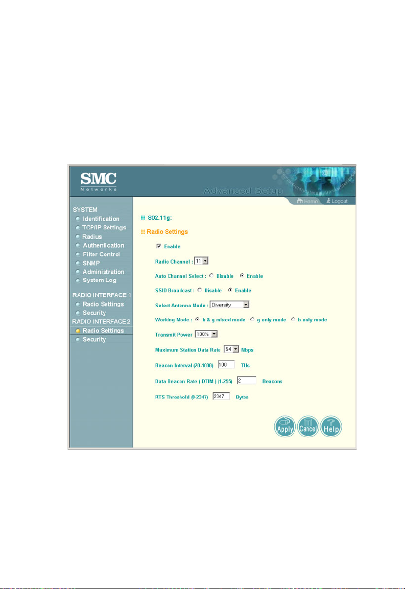
System Configuration
Radio Settings (802.11g)
The IEEE 802.11g standard operates within the 2.4 GHz band at
up to 54 Mbps. Also note that because the IEEE 802.11g
standard is an extension of the IEEE 802.11b standard, it allows
clients with 802.11b wireless network cards to associate to an
802.11g access point.
Enable – Enables radio communications on the SMC2555W-AG.
(Default: Enabled)
Radio Channel – The radio channel that the access point uses to
communicate with wireless cl ien ts. When multip le ac ces s points
are deployed in the same area, set the channel on neighboring
5-44
 Loading...