

Page 1

EZ Connect
™
W i r el es s Ca b l e M od em G a tew a y
Install Guide
SMC8013WG
Page 2

Copyright
Information furnished by SMC Networks, Inc. (SMC) is believed to be accurate and reliable.
H owever, no responsibility is assumed by SMC for its use, nor for any infringements of patents
or other rights of third parties which may result from its use. No license is granted by
implication or otherwise under any patent or patent rights of SMC. SMC reserves the right to
change specifications at any time without notice.
Copyright © 2004 by
SMC Networks, Inc.
38 Tesla
Irvine, California 926 18
All rights reserved.
T ra d e m a rk s
Information furnished by SMC Networks, Inc. (SMC) is believed to be accurate and reliable.
H owever, no responsibility is assumed by SMC for its use, nor for any infringements of patents
or other rights of third parties which may result from its use. No license is granted by
implication or otherwise under any patent or patent rights of SMC. SMC reserves the right to
change specifications at any time without notice.
Page 3

TABLE OF CONTENTS
CH AP T E R 1 | I n trod u c tion
F eatures and B enefits
P ackage Contents
Minimum R eq uirements
CH AP T E R 2 | G e ttin g to k n ow the W ire l e s s Ca b l e M od e m G a te w a y
L E D Indicators
R ear P anel Description
R esetting and R estoring the W ireless Cable Modem G ateway
CH AP T E R 3 | I n s ta l l a tion
B asic Installation P rocedure
CH AP T E R 4 | Con f igu rin g you r Com pu te r
Configuring W indows 95 / 98 / Me
Configuring W indows 2000
Configuring W indows X P
Configuring a Macintosh Computer
CH AP T E R 5 | Con f igu rin g the W ire l e s s Ca b l e M od e m G a te w a y
B rowser Configuration
Disable P rox y Connection
Accessing the W ireless Cable Modem G ateway W eb Management
CH AP T E R 6 | N a v iga tin g the W e b -b a s e d Ad m in is tra tion
Making Configuration Changes
System
L AN
W ireless
NAT
F irewall
Tools
Status
AP P E NDIX A | Troubleshooting
AP P E NDIX B | Technical Specifications
AP P E NDIX C | Compliances
AP P E NDIX D | Technical Support
Page 4
CH AP TER 1 | I n t r o d u c t i o n
Congratulations on your purchase of the E Z Connect™ W ireless Cable Modem G ateway. SMC is
proud to provide you with a powerful yet simple communication device for connecting your
local area network (L AN) to the Internet.
Fe a tu re s a n d B e n e f its
• E Z 3 -Cl ic k I n s ta l l a tion W iz a rd - A new and improved way to install your G ateway
Modem. In 3 simple clicks, you will be connected to the Internet.
• Internet connection to cable modem service via an integrated cable modem port
• L ocal network connection via 10/ 100 Mbps E thernet ports or 5 4 Mbps wireless
interface.
• 8 02.11g wireless - interoperable with multiple vendors.
• W ireless: W E P and W P A encryption, H ide SSID, and MAC F iltering
• DH CP for dynamic IP configuration, and DNS for domain name mapping.
• F irewall with Stateful P acket Inspection, client privileges, hacker prevention, DoS, and
NAT.
• V P N pass-through support using P P TP , L 2TP , or IP Sec
• U ser-definable application sensing tunnel supports applications req uiring multiple
connections
• B uilt-in P arental controls allow you to limit certain web sites – configurable by time
and date.
• E mail alerts when hacking attempts on the users network are made
• E asy setup through a web browser on any operating system that supports TCP / IP
• Compatible with all popular Internet applications
Page 5

P a c k a ge Con te n ts
B efore installing the E Z Connect™ W ireless Cable Modem G ateway, verify that you have the
items listed below.
• 1 - W ireless Cable Modem G ateway
• 1 - P ower adapter (9V / 1A)
• 1 - CAT-5 E thernet cable
• 1 - U SB Cable (Note: Depending on your cable operator, this may not be included)
• Installation CD, including (Note: Depending on your cable operator, this may not be
included):
o U ser G uide
o U SB Drivers
o B Safe O nline© P arental Control Software
If possible, retain the carton and original packing materials in case there is a need to return
the product.
P lease register your product on SMC’ s web site at http: / / www.smc.com.
S ys te m R e q u ire m e n ts
Y ou must meet the following minimum req uirements:
• P rovisioned Internet access from a cable operator that has approved the SMC8 013W G
• A computer eq uipped with a wired or wireless network adapter with TCP / IP installed.
• A J ava-enabled web browser, such as Microsoft Internet E x plorer 5 .5 or above, or
Netscape Communicator 5 .0 or above.
• W indows 98 Second E dition or higher is req uired for U SB driver support.
Page 6
CH AP TER 2 | G e t t i n g t o K n o w t h e W i r e l e s s Ca b l e M o d e m
G a t e w a y
The E Z Connect™ W ireless Cable Modem G ateway is the perfect all in one solution, for the
home or business environment. This full-featured device has:
• An approved DO CSIS 1.1 Cable modem
• Advanced SP I F irewall G ateway
• H igh-speed 5 4 Mbps 8 02.11g W ireless Access P oint
• Comprehensive L E Ds for network status and troubleshooting
• R eset B utton
• 4 – 10/ 100 Mbps Auto-Sensing L AN ports with Auto-MDI MDIX feature
• 1 – U SB 1.1 L AN P ort for P C connectivity (Note: Not supported by all cable operators)
N OT E : Cable modems provide up to 38 Mbps downstream and 10 Mbps upstream. H owever, you
should note that the actual rate provided by specific service providers may vary dramatically
from these upper limits.
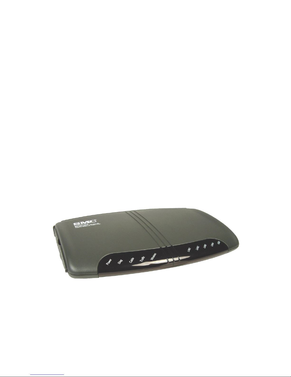
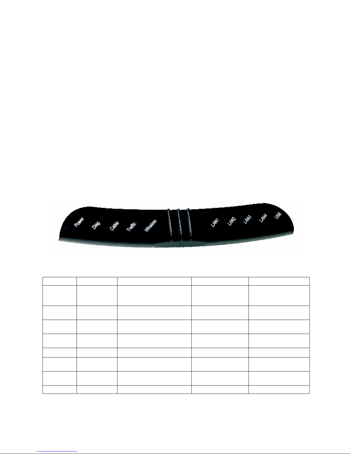
L E D I n d ic a tors
The E Z Connect™ W ireless Cable Modem G ateway includes L E D indicators on the front panel
that simplify installation and network troubleshooting.
The W ireless Cable Modem G ateway includes L E D indicators on the front panel that simplify
installation and network troubleshooting.
L AB E L L E D COL OR ON FL AS H I N G OFF
P ower G re e n
Diag Am b e r
Cable G re e n
Traffic G re e n
W ireless G re e n G ood W ireless L ink Data transmitting No W ireless L ink
L AN (1-4) Am b e r
L AN (1-4) G re e n
U SB G re e n U SB port connected Data transmitting No U SB link detected
P ower is supplied to the
G ateway
System F ailure. R eboot
G ateway
Successfully connected to
cable network
Cable Modem has finished
CMTS registration
Connected at 10 Mbps Data transmitting
Connected at 100 Mbps Data transmitting
N/ A
N/ A Normal O peration
Attempting to
connect to network
Attempting to
register with CMTS
P ower is not
supplied to the
G ateway
N/ A
N/ A
No E thernet link
detected
No E thernet link
detected
Page 7
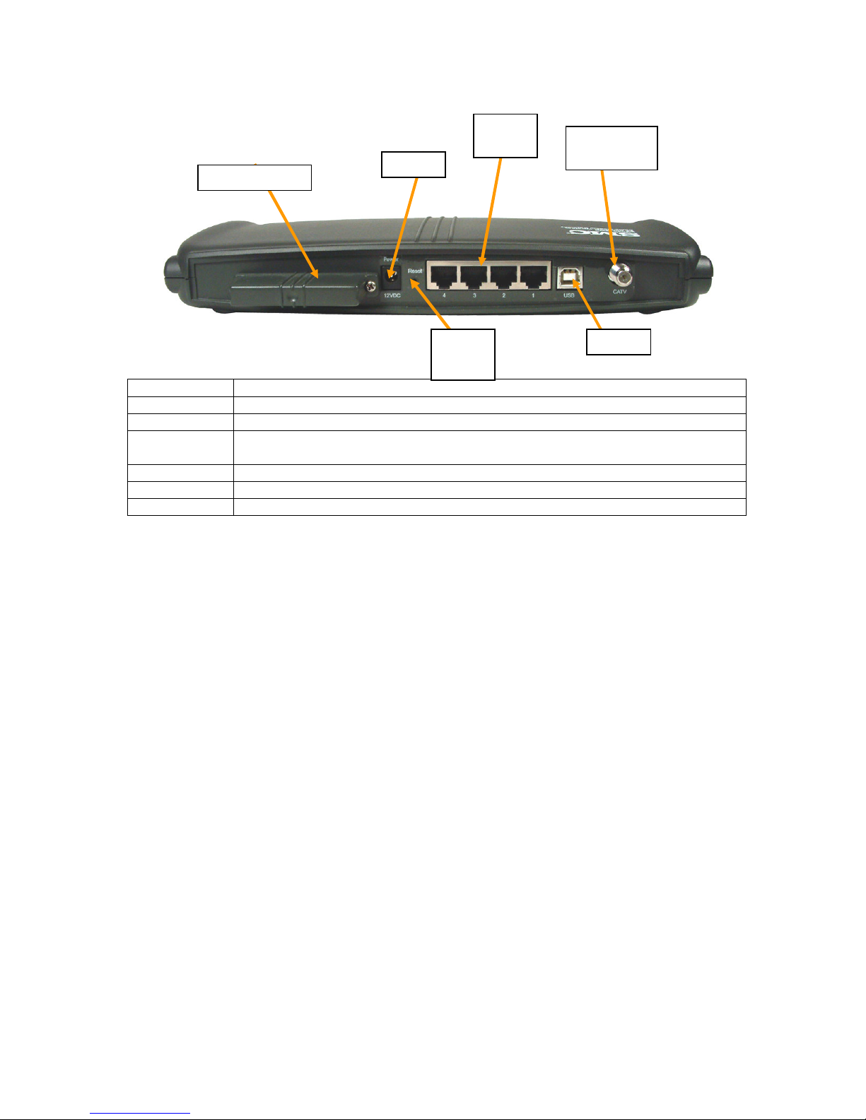
R e a r P a n e l D e s c ription
Wireless Card
P o w er
R eset
L A N
P o rt s
CA T V
Co n n ec t o r
U S B
B u t t o n
Item Description
P ower Connect the included power adapter to this port.
R eset U se this button to reset the power or restore the default factory settings.
L AN 1-4 F our 10/ 100 Auto-sensing switch ports (R J -45 ). Connect devices on your local
area network to these ports (such as a P C, hub, or switch).
U SB Connect a U SB Cable from your P C to this port.
CATV Connect your cable line to this port.
W ireless Card P rovides W ireless Signal for wireless clients.
R e b ootin g a n d R e s torin g the W ire l e s s Ca b l e M od e m G a te w a y
The R eset button is located on the rear panel of the E Z Connect™ W ireless Cable Modem
G ateway. U se a paper clip or a pencil tip to push the R eset button.
R e b oot
If the G ateway is having problems connecting to the Internet, simply hold down the reset
button for less than 2 seconds then release.
R e s tore Fa c tory D e f a u l ts
If rebooting the W ireless Cable Modem G ateway does not resolve your issue, then you can
follow these steps. Note: all configured settings will be erased.
1. L eave power plugged into the W ireless Cable Modem G ateway.
2. L ocate the reset button on the back panel, press and hold button for at least 5 seconds.
3. R elease reset button.
Page 8
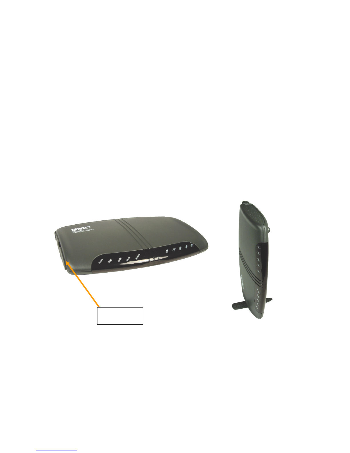
CH AP TER 3 | I n s t a l l a t i o n
V ert ic al B ase
S t an d
Horizontal Install
V e rtic al Install
The E Z Connect™ W ireless Cable Modem G ateway can be installed in any location where you
have cable internet access, and the cable internet service provider has approved the E Z
Connect™ W ireless Cable Modem G ateway. To confirm you meet these 2 criteria points, please
contact your cable operator.
F or general installation please follow the guidelines outlined below to best performance:
• K eep the W ireless Cable Modem G ateway away from any heating devices.
• Do not place the W ireless Cable Modem G ateway in a dusty or wet environment.
• F or optimum wireless performance, install the W ireless Cable Modem G ateway away
from other electronic devices, such as Monitors / TV / 2.4G H z Cordless P hones. These
devices can hamper your wireless throughput and distance.
The E Z Connect™ W ireless Cable Modem G ateway can be positioned two ways, horiz ontal and
vertical.
To install the W ireless Cable Modem in a vertical position, on the left side of the device, when
looking at the L E Ds – there is a built-in base stand. P ull out the stand out and turn it 90 degrees
and position the gateway on its side. See the different Install positions below:
Page 9
B a s ic I n s ta l l a tion P roc e d u re
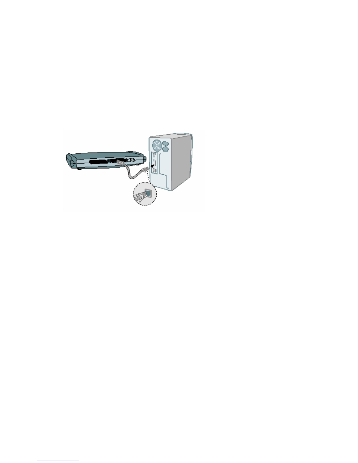
1. Con n e c t the L AN : Y ou can connect the W ireless Cable Modem G ateway to your P C, or to a
hub or switch. R un E thernet cable from one of the L AN ports on the rear of the W ireless
Cable Modem G ateway to your computer’ s network adapter or to another network device.
Y ou can use either a standard straight through or cross over E thernet cable since the
gateway incorporates Auto-MDI MDIX functionality.
Y ou can also connect the W ireless Cable Modem G ateway to your P C (using a wireless client
adapter) via radio signals.
N OT E : It is recommended that for first-time setup you use a wired connection.
2. Con n e c t the W AN : Connect a coax cable to the CATV port on the back of the W ireless
Cable Modem G ateway from a cable port located in your home. W hen connecting to the
CATV port, use only manufactured coax ial patch cables with F -type connectors at both
ends for all connections.
N ote : If this modem was NO T installed by the cable service provider (ISP ) or is being used
to replace another cable modem – please contact your Cable O perator (ISP ) to register the
SMC8 013W G . W ithout registering the modem with your ISP it will be unable to connect to
the cable network system.
3. P ow e r on : Connect the power adapter to the E Z Connect™ W ireless Cable Modem G ateway.
W a rn in g: O nly use the power adapter that was provided with the E Z Connect™ W ireless Cable
Modem G ateway, using another power adapter may damage your unit and void the warranty.
Page 10
CH AP TER 4 | Co n f i g u r i n g y o u r Co m p u t e r
The information outlined in this chapter will guide you through the configuration for the
following O perating Systems:
• W indows 95 / 98
• W indows Me
• W indows 2000
• W indows X P
• Apple Macintosh
Con f igu rin g W in d ow s 9 5/ 9 8 / M e
1. Access your Network settings by clicking
[ Start], choose [ Settings], and then select
[ Control P anel].
2. In the Control P anel, locate and double-click
the [ Network] icon.
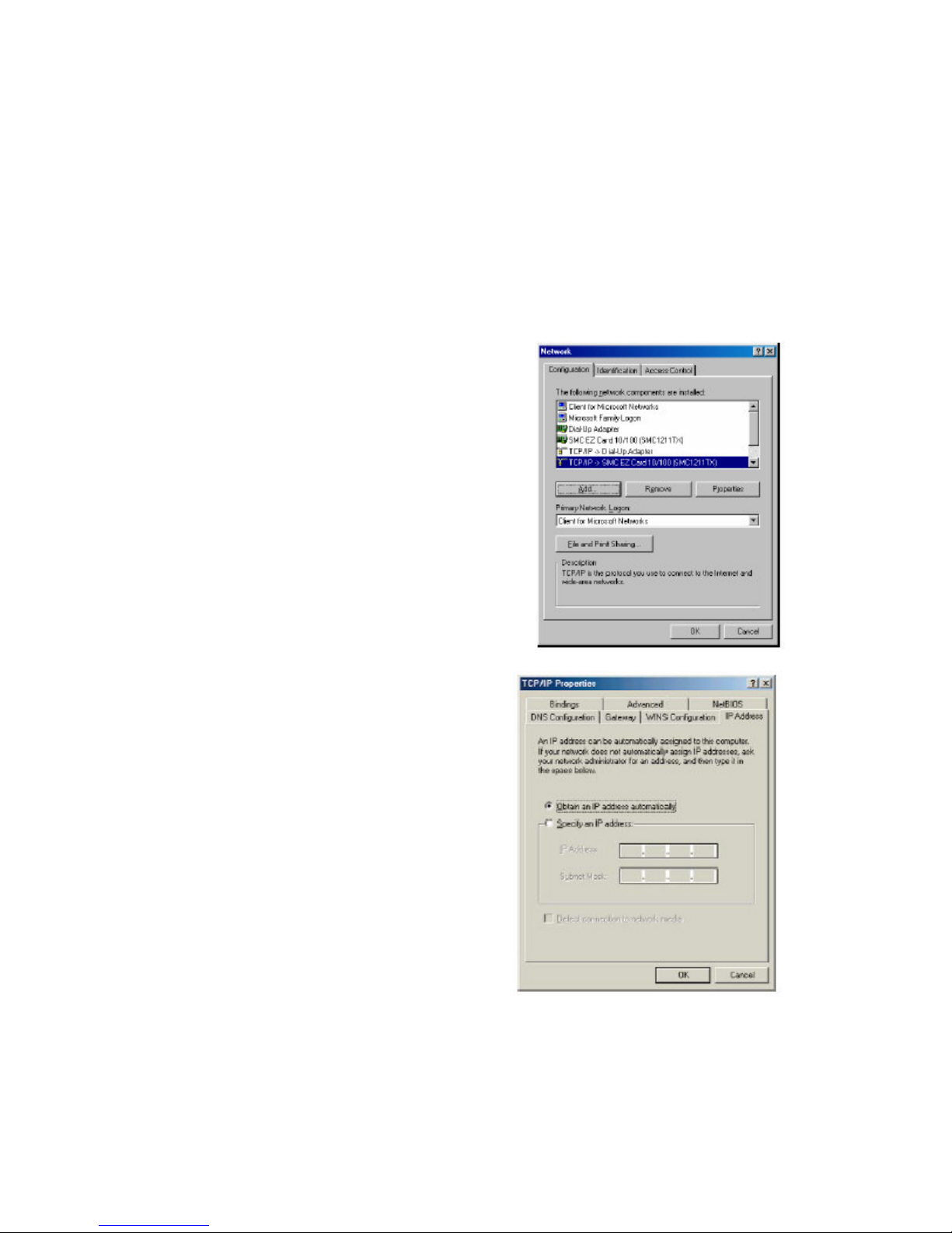
3. H ighlight the TCP / IP line that has been
assigned to your network card on the
[ Configuration] tab of the [ Network]
properties window. (see network dialog box to
the right)
4. Nex t, click the [ P roperties] button to view
that adapter’ s TCP / IP settings.
5 . F rom the TCP / IP P roperties dialog box , click
the [ O btain an IP address automatically]
option. (see TCP / IP dialog box to the
right)
6 . Nex t click on the [ G ateway] tab and verify
the G ateway field is blank. If there are IP
addresses listed in the G ateway section,
highlight each one and click [ R emove]
until the section is empty.
7 . Click the [ O K ] button to close the TCP / IP
P roperties window.
8 . O n the Network P roperties W indow, click
the [ O K ] button to save these new
changes.
N OT E : W indows may ask you for the
original W indows installation disk or
additional files. Check for the files at
c: \windows\options\cabs, or insert your W indows CD-R O M into your CD-R O M drive and
check the correct file location, for ex ample, D: \win98 , D: \win9x . (Assume “ D” is your
CD-R O M drive).
9. W indows may prompt you to restart the P C. If so, click the [ Y es] button. If W indows
does not prompt you to restart your computer, do so anyways to ensure your settings.
Page 11
Con f igu rin g W in d ow s 2 0 0 0
1. Access your Network settings by clicking
[ Start], choose [ Settings], and then
select [ Control P anel]
2. In the Control P anel, locate and double-
click the [ Network and Dial-up
Connections] icon
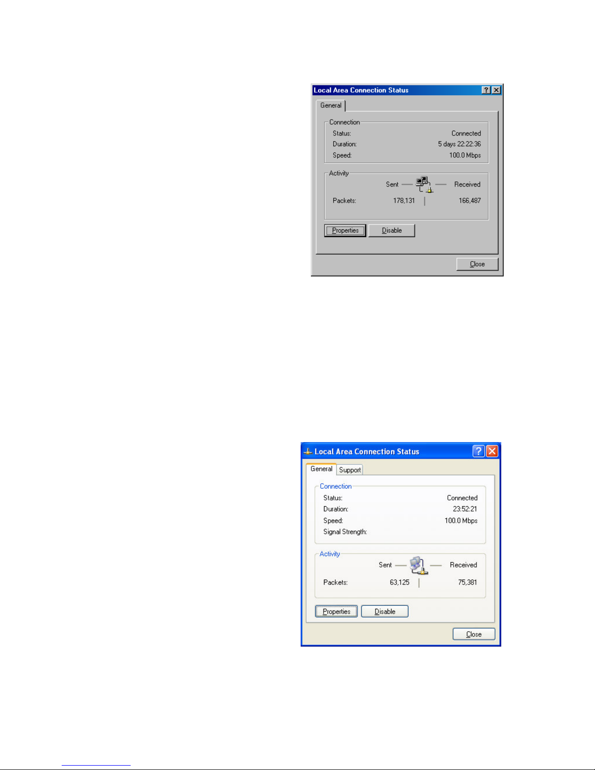
3. L ocate and double-click the [ L ocal Area
Connection] icon for the E thernet
adapter that is connected to the
G ateway. W hen the Status dialog box
window opens, click the [ P roperties]
button.
4. O n the [ L ocal Area Connection]
P roperties box , verify the box nex t to
Internet P rotocol (TCP / IP ) is checked.
Then highlight the Internet P rotocol (TCP / IP ), and click the P roperties button.
5 . Select O btain an IP address automatically to configure your computer for DH CP . Click
the [ O K ] button to save this change and close the P roperties window.
6 . Click the [ O K ] button again to save these new changes.
7 . R eboot your P C.
Con f igu rin g W in d ow s X P
The following instructions assume you are running W indows X P with the default interface. If
you are using the Classic interface (where the icons and menus look like previous W indows
versions), please follow the instructions for W indows 2000 outlined above.
1. Access your Network settings by
clicking [ Start], choose [ Control
P anel], select [ Network and Internet
Connections] and then click on the
[ Network Connections] icon.
2. L ocate and double-click the L ocal
Area Connection icon for the E thernet
adapter that is connected to the
W ireless Cable Modem G ateway. Nex t,
click the [ P roperties] button.
3. O n the [ L ocal Area Connection]
P roperties box , verify the box nex t to
Internet P rotocol (TCP / IP ) is checked.
Then highlight the Internet P rotocol
(TCP / IP ), and click the P roperties
button.
4. Select O btain an IP address automatically to configure your computer for DH CP . Click
the [ O K ] button to save this change and close the P roperties window.
5 . Click the [ O K ] button again to save these new changes.
Page 12
6 . R eboot your P C.
Con f igu rin g a M a c in tos h Com pu te r
Y ou may find that the instructions here do not ex actly match your screen. This is because these
steps and screen shots were created using Mac O S 10.2. Mac O S 7 .x and above are all very
similar, but may not be identical to Mac O S 10.2.
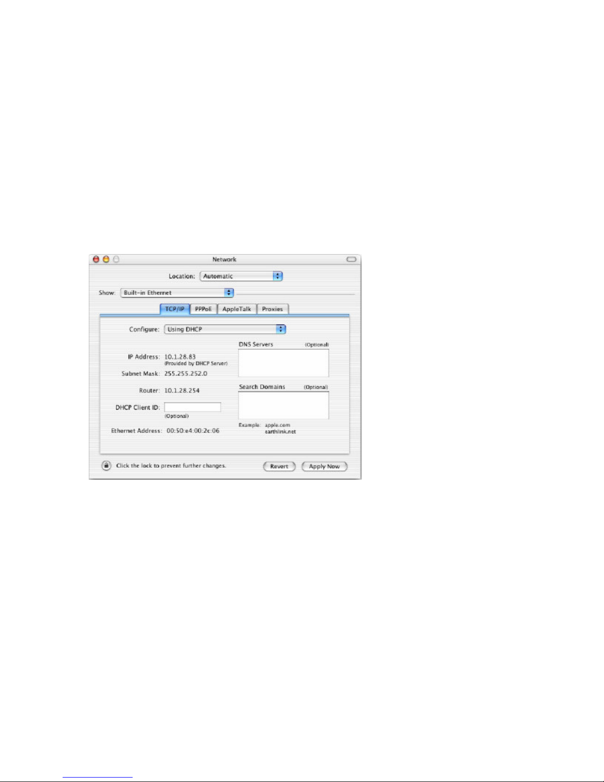
1. P ull down the Apple Menu. Click System P references and select Network. Make sure
that
2. B uilt-in E thernet is selected in the Show field.
3. O n the TCP / IP tab, select U sing DH CP in the Configure field.
4. Close the TCP / IP dialog box .
Page 13

CH AP TER 5 | Co n f i g u r i n g t h e W i r e l e s s Ca b l e M o d e m
G a t e w a y
After you have configured TCP / IP on a client computer, use a web browser to configure the E Z
Connect™ W ireless Cable Modem G ateway. The G ateway can be configured by any J avasupported browser including Internet E x plorer 5 .0 or above, or Netscape Navigator 5 .0 or
above. U sing the web management interface, you can configure the W ireless Cable Modem
G ateway features and view its settings.
B efore you attempt to log into the W ireless Cable Modem G ateway’ s W eb-based
Administration, please verify the following:
1. Y our browser is configured properly. (see below)
2. Disable any firewall or security software that may be running.
3. Confirm that you have a [ link] L E D where your computer is plugged into the W ireless
Cable Modem G ateway. If you don’ t have a [ link] light, try another cable.
B row s e r Con f igu ra tion
Confirm your browser is configured for a direct connection to the Internet using the E thernet
cable that is installed in the computer. This is configured through the options/ preference section
of your browser.
D is a b l e P rox y Con n e c tion
Y ou will also need to verify that the “ H TTP P rox y” feature of your web browser is disabled. This
is so that your web browser will be able to view the web-based configuration pages. The
following steps are for Internet E x plorer and for Netscape. Determine which browser you use and
follow the appropriate steps.
I n te rn e t E x pl ore r ( 5.0 or a b ov e )
1. O pen Internet E x plorer. Click [ Tools], and then select [ Internet O ptions].
2. In the [ Internet O ptions] window, click the [ Connections] tab.
3. Click the [ L AN Settings] button.
4. Clear all the check box es and click [ O K ] to save these L AN settings changes.
5 . Click [ O K ] again to close the [ Internet O ptions] window.
N OT E : To ensure proper screen refresh after a command entry, be sure that Internet E x plorer
5 .0 is configured as follows: U nder the menu “ Tools/ Internet O ptions/ G eneral/ Temporary
Internet F iles/ Settings,” the setting for “ Check for newer versions of stored pages” should be
“ E very visit to the page.”
N e ts c a pe ( 5.0 or a b ov e )
1. O pen Netscape. Click [ E dit], and then select [ P references].
2. In the [ P references] window, under [ Category], double-click [ Advanced], and then
select the [ P rox ies] option.
3. Check [ Direct connection to the Internet].
4. Click the [ O K ] button to save the changes.
Page 14

Ac c e s s in g the W ire l e s s Ca b l e M od e m G a te w a y’ s W e b M a n a ge m e n t
To access the W ireless Cable Modem G ateway’ s web-based management screens, follow the
steps below:
1. L aunch your web-browser.
N OT E : Y our computer does not have to be O NL INE to configure the W ireless Cable
Modem G ateway. Depending on your cable operator, the default IP address of the
gateway is either 10.1.10.1 or 192.16 8 .0.1.
2. In the Address B ar, type: http: / / 10.1.10.1
N OT E : F or some browsers, it may be necessary to include: 8 0 after the management IP
address. F or ex ample:
http: / / 10.1.10.1: 8 0
3. W hen the G ateway’ s L ogin screen appears, enter the default username and password,
and click the [ L ogin] button to access the W ireless Cable Modem G ateway.
P lease contact your cable operator for login and password information.
N OT E : U sernames and P asswords are case sensitive
4. O nce you have logged into the G ateway’ s web-based admin screen, you have several
options and features which can be configured.
All features available and how to configure each one is outlined in the nex t section
Cha pte r 6 | N a v iga tin g the W e b -b a s e d Ad m in is tra tion .
Page 15

CH AP TER 6 | Na v i g a t i n g t h e W e b -b a s e d Ad m i n i s t r a t i o n
The E Z Connect™ W ireless Cable Modem G ateway’ s management interface allows you to
configure both basic and advanced features and options. Some of these advanced functions
include: hacker attack detection, IP and MAC address filtering, intrusion detection, port
forwarding setup, virtual DMZ hosts, as well as other advanced functions.
M a k in g Con f igu ra tion Cha n ge s
O nce a configuration change has been made on a page, be sure to click the [ Apply] or [ Nex t]
button at the bottom of the page to enable the new setting.
SYSTEM
P a s s w ord S e ttin gs
F rom this section you can configure new passwords.
Y ou can also set the Idle Time O ut value that the SMC8 013W G will keep an account logged in
for. The default Idle Time O ut value is 10 min.
To access the P assword Settings configuration page, on the Side Navigation bar, click on
[ System] link and then click on the [ P assword Settings] link.
If your password is lost, or you cannot gain access to the user interface, contact your cable
operator.
L A N (
F rom this section you can configure the following settings:
To access the L AN configuration page, on the Side Navigation bar, click on [ L AN] link.
L AN I P
U se the L AN section to configure the L AN IP address for the W ireless Cable Modem G ateway and
to enable the DH CP server for dynamic client address allocation. Y ou can also configure the
L ease Time for the DH CP clients on your network.
Note: Depending on your cable operator, this option may not be available)
• E nable or Disable the integrated DH CP server
• Configure the DH CP L ease time for your DH CP clients
• The IP Address P ool range for DH CP clients
Page 16

P rivate L AN IP Settings
DH CP Server Settings
I P Ad d re s s P ool
A dynamic IP start address may be specified by the user, e.g. 10.1.10.1 (one possible default
value). O nce this start IP address has been assigned, IP addresses running from 10.1.10.10 to
10.1.10.199 will be part of the dynamic IP address pool. IP addresses from 10.1.10.230 to
10.1.10.25 3 will be available as static IP addresses.
N OT E : Do not to include the address of the E Z Connect™ W ireless Cable Modem G ateway
(10.1.10.1 – default IP ) in the client address pool.
W I R EL ESS (
Note: Depending on your cable operator, this option may not be available)
This section allows you to configure the W ireless Cable Modem G ateway’ s built-in 5 4 Mbps
8 02.11g Access P oint. To setup the wireless connections, you will need to do define the
Channel, the Service Set Identifier (SSID), E ncryption options, and other optional settings.
To access the W ireless Settings page shown below, on the Side Navigation bar, click on
[ W ireless] link.
Page 17

N OT E : If you are not using this W ireless Cable Modem G ateway with W ireless clients it is
recommended that you disable the W ireless Mode.
Cha n n e l a n d S S I D
Y ou must specify a common radio channel and SSID (Service Set ID) to be used by the G ateway
and all of your wireless clients. B e sure you configure all of your clients to the same values.
To access the Channel and SSID configuration page, on the Side Navigation bar, click on
[ W ireless] link and then click on the [ Channel and SSID] link.
S S I D : This is the W ireless ID or Service Set ID of your wireless network. This should be set to
the same value as the other wireless devices in your network.
N OT E : The SSID is case sensitive and can consist of up to 32 alphanumeric characters.
Cha n n e l : The radio channel through which the G ateway communicates to clients over the
wireless network.
N OT E : If you are not getting good wireless performance try another wireless channel – because
this G ateway operates in the 2.4G H z spectrum – it can be affected by some other products,
such as cordless phones.
H id e S S I D : This option cause the gateway to not broadcast its SSID. B y selecting this option,
wireless clients will not be able to use their Site Survey feature to locate this wireless network.
Page 18

E n c ryption
If you are transmitting sensitive data across wireless channels, you should enable either W ired
E q uivalent P rivacy (W E P ) or W iF i P rotected Access (W P A) encryption. E ncryption req uires you
to use the same set of encryption/ decryption keys for the W ireless Cable Modem G ateway and
all of your wireless clients.
To access the E ncryption configuration page, on the Side Navigation bar, click on [ W ireless] link
and then click on the [ E ncryption] link.
W E P
Select [ W E P ] from the [ E ncryption Type] drop down menu. Select the Automatic, O pen System,
or Shared K ey from the [ W E P Authentication Type] drop down menu.
Y ou can choose between standard 6 4-bit or 128 -bit encryption keys. B elow is a screen shot of
the configuration options for 6 4-bit W E P , you can configure this security option with a
passphrase key or a manual key.
N OT E : To enter a manual W E P key you will need to enter hex adecimal values (A-F and 0-9).
Page 19

To automatically generate a 6 4-bit W E P key, enter in a P assphrase (e.g. H ome) and click the
[ G enerate K eys] option. O nce you do this, the G ateway will dynamically generate 4 keys.
Simply configure the Default K ey to the one key that you will be using across your network.
O n the wireless clients, you can use the passphrase option, and client utility will generate the
same 4 keys – or you can manually type in the selected K E Y that is configured on the G ateway.
F or more security, you can use 128 -bit W E P encryption. To use this mode, click the [ 128 B it
E ncryption] option and the configuration section will be displayed. Y ou can manually enter in
the 26 -digit hex adecimal key or use the passphrase option to generate random dynamic keys.
N OT E : If you are having a difficult time getting the wireless connection up after enabling W E P –
please confirm that you have configured the SAME W E P key on both the W ireless Cable Modem
G ateway and Client card.
W P A
Select [ W P A] from the [ E ncryption Type] drop down menu. Nex t, enter a passphrase value
between 8 and 6 3 characters in the [ W P A P assphrase] field.
M AC Fil te rin g
The W ireless Cable Modem G ateway can allow the wireless client stations to connect over a
wireless connection in 2 different ways:
Page 20

1. B y allowing all wireless stations access;
2. O r by allowing only Trusted P Cs.
To access the MAC F iltering configuration page, on the Side Navigation bar, click on [ W ireless]
link and then click on the [ MAC F iltering] link.
Y ou can also configure a [ Device Name] that is associated with a specific MAC address. In doing
this, you can easily recogniz e the computers that you are in your access list.
N OT E : MAC filtering only applies to W ireless Clients.
N A T
(Note: Depending on your cable operator, this option may not be available)
Network Address Translation (NAT) allows multiple users at your local site to access the
Internet through a single public IP address.
P ort Forw a rd in g
The W ireless Cable Modem G ateway supports port forwarding that enables customers to host
servers on their L AN. Y ou can configure this feature to redirect the ex ternal service req uest to
the appropriate internal server and port.
F or ex ample, if you are running a W E B server, you can configure all traffic on port 8 0 to be
redirected to the IP address of the W E B server running on your network.
To access the P ort F orwarding configuration page, on the Side Navigation bar, click on [ NAT]
link and then click on the [ P ort F orwarding] link.
Page 21

This P ort F orwarding function supports 2 types of Services:
• P redefined Service
• Customer Defined Service
P re d e f in e d S e rv ic e
The P redefined Service option has a pull-down menu with several popular Service Applications,
such as H TTP (8 0), F TP (20/ 21), and AIM/ ICQ (5 190).
To configure the virtual server for a P redefined Service, follow the steps below:
1. Select the [ Service] that you want to have access through the firewall to your L AN from
the pull-down menu.
2. E nter in the [ L AN Server IP ] for the L AN P C that is running this service or application
3. Y ou can also configure [ R emote IP s] option to allow access to this specific port from
the W AN side. This can be configured for 3 different access types:
a. Any IP Address [ Any] – choose this option to allow access to any public IP
address.
b. Single IP Address [ Single Address] – choose this option to allow access to a
single public IP address.
c. IP Address R ange [ Address R ange] – choose the option to allow a range of public
IP addresses.
4. Click the [ Apply] button to save your changes and return to the P ort F orwarding main
screen
Page 22

Cu s tom e r D e f in e d S e rv ic e ( Cu s tom )
The Customer Defined Service section allows you to configure the P ort F orwarding option to
any Traffic type (TCP / U DP / TCP and U DP ), any P ublic P ort, and any P rivate P ort.
To configure this custom option, please follow the steps below:
1. E nter in a Description [ Name] for this custom setting
2. Configure the Traffic or Data [ Type] that you want to forward. The options are TCP |
U D P | TCP/ U D P.
3. Set the [ L AN Server IP ] of the P C that you want this traffic/ data redirected to
4. Y ou can also configure [ R emote IP s] option to limit access to this specific port from the
W AN side. This can be configured for 3 different access types:
a. Any IP Address [ Any] – choose this option to allow access to any public IP
address.
b. Single IP Address [ Single Address] – choose this option to allow access to a
single public IP address.
c. IP Address R ange [ Address R ange] – choose the option to allow a range of public
IP addresses.
5 . Set the [ P ublic P ort] that this application will use on the W AN (Internet) side
6 . Set the [ P rivate P ort] that the L AN P C will be waiting for this traffic/ data from
B elow is an ex ample setting for a W E B server on an internet connection, where port 8 0 is
blocked from the W AN side, but port 8 000 is available.
Name: W eb Server
Type: TCP
L AN Server IP : 10.1.10.100
R emote IP s: Any (allow access to any public IP )
P ublic P ort: 8 000
P rivate P ort: 8 0
W ith this configuration, all H TTP (W eb) TCP traffic on port 8 000 from any IP Address from the
W AN side will be redirected through the firewall to the Internal Server (10.1.10.100) on port
8 0.
N OT E : This configuration is useful because you don’ t have to reconfigure your web server to
accept traffic on a different port, you can do this configuration on the gateway.
Page 23

F I R EW A L L
The W ireless Cable Modem G ateway provides a stateful packet inspection firewall (SP I), which
is designed to protect against Denial of Service (DoS) attacks. Its purpose is to allow a private
local area network (L AN) to be securely connected to the Internet. To provide a flex ible
solution, the firewall section has the following features:
Ac c e s s Con trol
The Access Control section allows the setting of two types of rules: enable access to services on
your public LAN network from the Internet or to block services on the pr iv a t e LAN from
accessing the Internet. Access R ules can be configured to a specific L AN IP Address or a range
of L AN IP Address’ s.
To access the Access Control configuration page, on the Side Navigation bar, click on [ F irewall]
link and then click on the [ Access Control] link.
To enable this feature, check the [ E nable Access Control] checkbox .
There are 2 sections that can be configured for Access Control R ules.
The first section is used to configure the Access R ules for the P ublic L AN from the Internet.
These rules will enable services on the public L AN to be accessed by the Internet. Note:
Depending on your cable operator, this option may not be available.
The second section is used to configure Access R ules for the P rivate L AN to the Internet. These
rules will block services on the private L AN to the Internet.
F rom this section, you can also choose to have the W ireless Cable Modem G ateway to [ R espond
to P ing on Internet W AN P ort]. If you check this option, the G ateway will respond to P ING
req uests to the W AN IP address. B y Default this option is enable.
Page 24

F or convenience, each Access Control section includes 2 filtering options:
• P redefined F iltering
• Customer Defined F iltering
Steps to configure both types of these Access R ules are outlined below:
Con f igu rin g a P re d e f in e d Fil te rin g Ac c e s s R u l e :
1. O n the Side Navigation bar, click on [ F irewall] then select [ Access Control]
2. U nder the P redefined Section, click on the [ Add] button
3. O n the nex t page, select the service that you want to block from the pull-down menu
4. Select the [ L AN IP s] that you want this access rule to apply to. Y ou can choose to apply
this rule to Any IP Address, a Single IP Address, or a R ange of IP Addresses.
If you choose [ Any] for the L AN IP s you don’ t need to configure the [ Start IP ] or [ E nd IP ]
options.
If you choose [ Single address] enter in the L AN IP address of the P C into the [ Start IP ]
section.
If you choose [ Address R ange] enter in the starting L AN IP address in the [ Start IP ]
section and enter in the ending L AN IP address of the range you want in the [ E nd IP ]
section.
5 . W hen your configuration is complete, click the [ Apply] button to save your changes and
return to the main Access Control page.
Con f igu rin g a Cu s tom e r D e f in e d Fil te rin g Ac c e s s R u l e :
1. O n the Side Navigation bar, click on [ F irewall] then select [ Access Control]
2. U nder the Customer Defined Section, click on the [ Add] button
3. O n the Customer F ilter Configuration page, define a Name for the service/ application
that you want to block.
Page 25

N OT E : The Name is only for reference purposes.
4. Then select the protocol type from the pull-down menu that they would like to block.
The options are TCP | U D P | TCP/ U D P.
5 . Select the [ L AN IP s] that you want this access rule to apply to. Y ou can choose to apply
this rule to Any IP Address, a Single IP Address, or a R ange of IP Addresses.
If you choose [ Any] for the L AN IP s you don’ t need to configure the [ Start IP ] or [ E nd IP ]
options.
If you choose [ Single address] enter in the L AN IP address of the P C into the [ Start IP ]
section.
If you choose [ Address R ange] enter in the starting L AN IP address in the [ Start IP ]
section and enter in the ending L AN IP address of the range you want in the [ E nd IP ]
section.
6 . To complete the configuration enter in the [ F rom P ort] and [ To P ort] information will
be blocked on the network.
N OT E : U sually every application has its own corresponding port number. U sers should
find out the correct port number from the application vendor. F or ex ample, if you are
trying to block access to a P eer-2-P eer file sharing application then you should visit
that applications web site to see the ports it works with.
7 . W hen your configuration is complete, click the [ Apply] button to save your changes and
return to the main Access Control page.
S pe c ia l Appl ic a tion (Note: Depending on your cable operator, this option may not be available)
Some applications, such as Internet gaming, videoconferencing, Internet telephony and others,
req uire multiple connections. R ules are based on the port or range of ports that the
application sends data to the server on. W hen the gateway sees traffic sent to the configured
port(s), it dynamically allows all incoming traffic from the server on any port for the specified
time.
To access the Special Application configuration page, on the Side Navigation bar, click on
[ F irewall] link and then click on the [ Special Application] link.
To enable this option, click the [ E nable Triggering] checkbox .
Page 26

To configure a Special Application R ule, follow the steps outlined below:
1. O n the Side Navigation bar, click on [ F irewall] then select [ Special Application]
2. Click on the [ Add] button on the Special Application page to access the [ Trigger]
configuration section.
3. E nter in the [ Name] that you want to use for this rule.
4. In the [ Type] pull-down menu, select the data/ traffic type that this rule will apply to.
The options are TCP | U D P.
5 . Configure the [ P ort Number] that your application will be using as the outgoing trigger
ports.
6 . Set the [ Interval] of the rule. This is the time in between the outgoing and incoming
data traffic.
N OT E : If you set this value to low, the incoming ports will be closed before the return
data arrives at the firewall and the connection will be broken and the application will not
work.
7 . The last 2 options are for Advanced U sers, most users can leave this at the default
settings:
• IR R eplacement – Default Setting: Disable address replacement
• Allow sessions initiated from/ to the 3rd host – Default Setting: unchecked
8 . W hen your configuration is complete, click the [ Apply] button to save your changes and
return to the main Special Application page.
U R L B l oc k in g
This section allows you to control the content network. This feature is good for both business
and parents looking to control the content accessible from a web browser.
Page 27

To access the U R L B locking configuration page, on the Side Navigation bar, click on [ F irewall]
link and then click on the [ U R L B locking] link.
To enable this option, click the [ E nable K eyword B locking] checkbox
To configure U R L blocking, follow the steps outlined below:
1. O n the Side Navigation bar, click on [ F irewall] then select [ U R L B locking]
2. Check the [ E nable K eyword B locking] checkbox to turn U R L blocking on.
3. E nter in a new keyword or U R L address that you want to block in the [ K eyword/ Domain
Name] input box .
4. P ress the [ Add K eyword] button to save this keyword or U R L .
5 . The new keyword or U R L address would be listed in the tex t box below.
N OT E : This list will support 24 K eywords or U R L s.
If you want a P C on your network to bypass these rules you will need to set that P C as an
E x empted P C/ Trusted H ost. To configure this option, check the [ Add Trusted H ost] option and
enter the L AN IP address of the P C that you want to bypass the U R L / K eyword blocking function
with.
S c he d u l e R u l e
This feature will block Internet content based on the U R L blocking function for P Cs on your
network based on the day and or time.
N OT E : The U R L / K eyword blocking feature must be configured to use this schedule rule.
To access the Schedule R ule configuration page, on the Side Navigation bar, click on [ F irewall]
link and then click on the [ Schedule R ule] link.
Page 28

To enable this option, click the [ E nable Schedule F unction] checkbox .
To configure Schedule R ules, follow the steps outlined below:
1. O n the Side Navigation bar, click on [ F irewall] then select [ Schedule R ule]
2. In the [ W eek Day] table check the Days that you want to apply U R L / K eyword B locking.
3. Define the appropriate settings for a schedule rule.
4. Click the [ O K ] button to approve rule.
5 . Then click the [ AP P L Y ] button to save your settings.
E m a il / S ys l og Al e rt (Note: Depending on your cable operator, this option may not be available)
The W ireless Cable Modem G ateway can provide network log and alert information to keep you
updated. The G ateway can send an e-mail to as many as 4 users alerting them of an attempted
intrusion or hacker attack. The G ateway also supports a Syslog Client so you can ex port your
Network L og entries to a Syslog Server.
To access the E mail/ Syslog Alert configuration page, on the Side Navigation bar, click on
[ F irewall] link and then click on the [ E mail/ Syslog Alert] link.
Page 29

There are 3 sections to configure on this page:
• E mail Alerting
• Syslog Alerting
• Alerting Schedule
To enable the E mail Alert feature, click the [ E nable E mail Alerting] checkbox .
F ollow the steps below to configure the E mail Alert feature:
1. E nter in your SMTP Server Address (this is also referred to as the outgoing mail server)
2. E nter in the [ Sender’ s E -mail Address] – this is the email address that is associated with
the outgoing mail server account.
3. E nter in your email [ U ser Name].
4. E nter in your email [ P assword].
N OT E : If you don’ t have your SMTP or outgoing mail server information, please contact
your ISP .
Page 30

5 . To add an email address to the Alert L ist, click the [ Add] button. The configuration
page shown below will be displayed:
N OT E : The email alert feature will allow you to send email alerts to 4 different email
accounts. F or ex ample you could send an email to your home, work, and school email
address.
6 . E nter in the [ Name] of the person/ account that you want to send this to
7 . E nter in the [ R ecipient’ s E mail Address] as the email address you want to send the
alert to
8 . W hen complete, click the [ Apply] button to save your settings and return to the main
E mail/ Syslog Alert configuration page
If you need to edit or delete an ex isting email account, follow the steps below
1. Check the radio button nex t to the
email entry
2. Click the [ E dit] or [ Delete] button.
To enable the Syslog Alert feature, click the [ E nable Syslog Alerting] checkbox .
To configure the Syslog Server, enter the L AN IP of the [ Syslog Server Address].
Page 31

Immediate Alerts can be generated for both the email and Syslog alerts. To configure the type
of Alert that you want to get:
- An Intrusion is detected – this is a hacker attack attempt from the W AN
- Attempts to access a blocked site – alert to any attempts to access a site or keyword listed in
your U R L / B locking list.
1. To get regular alerts on timed schedule, select H ourly, Daily, or W eekly from the
[ Notification Schedule] pull down menu.
N OT E : If you don’ t want to configure a schedule – leave this option to the default
[ None].
O n this Notification Schedule feature you can configure the specific [ Day] and [ Time]
that the Alert is sent out.
D M Z H os t (Note: Depending on your cable operator, this option may not be available)
If you have a client P C that cannot run an Internet application properly from behind the
firewall, then you can open the client up to unrestricted two-way Internet access. E nter the IP
address of a DMZ host to this screen. Adding a client to the DMZ (Demilitariz ed Z one) may
ex pose your local network to a variety of security risks, so only use this option as a last resort.
To access the DMZ configuration page, on the Side Navigation bar, click on [ F irewall] link and
then click on the [ DMZ ] link.
To enable this option, click the [ E nable DMZ H ost] checkbox .
To configure a DMZ host, E nter in the L AN IP Address of the P C on your network in the input
fields.
Page 32

TO O L S
R e b oot (Note: Depending on your cable operator, this option may not be available)
In the event that the system stops responding correctly or functioning properly, you can
perform a reboot.
To access the R eboot option page, on the Side Navigation bar, click on [ Tools] link and then
click on the [ R eboot] link.
To reboot the W ireless Cable Modem G ateway, follow the steps below:
1. Click the [ Apply] button
2. Click [ O K ] on the confirmation dialog box
3. The G ateway will reboot.
N OT E : The R eboot will be complete when the power L E D stops blinking.
STA TU S
The Status screen displays W AN/ L AN connection status, firmware, and hardware version
numbers, illegal attempts to access your network, as well as information on DH CP clients
connected to your network.
Page 33

The Network log shows both firewall and network activity.
The DH CP Client L og shows the clients connected to the W ireless Cable Modem G ateway and
the type of connection (E thernet or W ireless). This also shows the IP address assigned to the
client and the MAC Address of the client’ s network adapter.
The Cable Modem System E vent L og shows diagnostic information about your connection and
cable system. Note: Depending on your cable operator, this option may not be available.
The Cable Status page shows the users the initializ ation process the SMC8 013W G has been
through, and also includes the information about the downstream channel and the upstream
channel the modem is connected on.
Page 34

AP P END I X A | Tr o u b l e s h o o t i n g
This appendix describes common problems you may encounter and possible solutions to them.
A.1 | V e rif y you a re c on n e c te d to the W ire l e s s Ca b l e M od e m G a te w a y
If you are unable to access the G ateway’ s web-based administration pages, then you may not
be properly connected or configured. The screen shots in this section were taken on a W indows
2000 machine, but the same steps will apply to W indows 95 / 98 / Me/ X P .
To determine your TCP / IP configuration status, please follow the steps below:
1. Click [ Start] then choose [ R un]
2. Type “ cmd” or “ command” (without the q uotes) to open a DO S prompt.
3. In the DO S window, type “ ipconfig” and verify the information that is displayed.
4. If you computer is setup for DH CP , then your TCP / IP configuration should be similar to
the information displayed:
• IP Address: 10.1.10.X (x is number between 100 and 199; Note: depending on your
cable operator, the default IP address of the gateway may be 192.16 8 .0.1)
• Subnet: 25 5 .25 5 .25 5 .0
• G ateway: 10.1.10.1
If you have an IP address that starts with 16 9.25 4.X X X .X X X then see section A.2.
If you have another IP address configured, see section A.3.
A.2 | I a m ge ttin g a n I P Ad d re s s tha t s ta rts w ith 1 69 .2 54 .X X X .X X X
If you are getting this IP Address, then you need to check that you are properly connected to
the E Z Connect™ W ireless Cable Modem G ateway.
Confirm that you have a link light on the G ateway’ s port to which this computer is connected.
If not, please try another E thernet cable.
If you have a link light, please open up a DO S window as described in section A.1 and type
“ ipconfig / renew” (without the q uotes)
Page 35

If you are still unable to get an IP Address from the W ireless Cable Modem G ateway, reinstall
your network adapter. If anti-virus software is running on your computer, disable it before
reinstalling the network adapter. P lease refer to your adapter manual for instructions.
A.3 | I ha v e a n othe r I P Ad d re s s d is pl a ye d
If you have another IP address listed, then the P C may not be configured for a DH CP
connection. P lease refer to Cha pte r 4 | Con f igu re you r Com pu te r for information.
O nce you have confirmed your computer is configured for DH CP , follow the steps below.
1. O pen a DO S window as described above.
2. Type “ ipconfig / release” (without the q uotes)
3. Then type “ ipconfig / renew” (without the q uotes)
O nce you are able to get a valid IP address from the W ireless Cable Modem G ateway, you can
now access the web-based Administration pages. Depending on your cable operator, the
default IP address of the gateway is either 10.1.10.1 or 192.16 8 .0.1.
If you still are not getting an IP address from the G ateway, please reset the hardware as
outlined in Chapter 2 and follow the steps outlined in this appendix again. Note: all configured
settings will be erased.
If you still cannot access the G ateway once you have reset it, please contact your cable
operator for assistance.
Page 36

A.4 | P in gin g the W ire l e s s Ca b l e M od e m G a te w a y
To verifying Y our TCP / IP Connection is configured properly and you are able to access the
W ireless Cable Modem G ateway’ s web-based management screens – you can use the ‘ P ing’
command in DO S.
To access the DO S dialog window please follow the steps below:
1. Click Start, then choose R un
2. W indows 98 / Me users type “ command” and click the [ O K ] button.
W indows 2000/ X P users type “ cmd” and click the [ O K ] button.
3. At the prompt, type: ping 10.1.10.1 (Depending on your cable operator, the default IP
address of the gateway is either 10.1.10.1 or 192.16 8 .0.1).
After you click [ enter] to ex ecute the P ING command you will get some information
back, below is an outline of the possible return messages:
G ood Con n e c tion
B a d Con n e c tion
There may be something wrong in your installation procedure. Check the following
items in seq uence:
1. Is the E thernet cable correctly connected between the G ateway and the computer?
2. The L AN L E D on the G ateway and the L ink L E D of the network card on your
computer must be on.
3. Is TCP / IP properly configured on your computer?
Page 37

A.5 | S ym ptom / Ac tion T rou b l e s hootin g
The G ateway can be easily monitored through panel indicators to identify problems. P lease
refer to Chapter 2 – Section 2.0 | L E D Definitions to confirm you have the correct L E D status. If
not, then refer to the symptoms and actions outlined below:
S Y M P T ON : P ow e r L E D is Of f
ACTIO N:
• Check connections between the G ateway, the ex ternal power supply, and the wall
outlet.
• If the power indicator does not light when the power cord is plugged in, you may have
a problem with the power outlet, power cord, or ex ternal power supply.
• If the unit powers off after running for a while, check for loose power connections,
power losses, or surges at the power outlet.
• If you cannot isolate the problem, then the ex ternal power supply may be defective. In
this case, contact your cable operator for assistance.
S Y M P T ON : D ia g L E D is On
ACTIO N:
• P ower Cycle the G ateway. U nplug the G ateway – wait 5 seconds – plug it back into
power.
• If the Diag L E D is still on, reset the hardware as outlined in Chapter 2 and power cycle
the gateway again.
• If this does not resolve your problem, contact your cable operator for assistance.
S Y M P T ON : Ca b l e L E D is Of f or Fl a s hin g
ACTIO N:
• P ower Cycle the G ateway. U nplug the G ateway – wait 5 seconds – plug it back into
power.
• Confirm your cable operator is not having network issues and the network is up and
running.
• If you cannot isolate the problem contact your cable operator for assistance.
S Y M P T ON : W ire l e s s L E D is Of f
ACTIO N:
• Check to insure the wireless card in the back panel is firmly plugged into the card slot.
If not, unplug gateway and put the wireless card firmly into the P C Card slot.
• Confirm wireless option is enabled in the web-management
• R eboot the G ateway.
• If you cannot isolate the problem contact your cable operator for assistance.
S Y M P T ON : Ca n n ot c on n e c t u s in g the w e b b row s e r
ACTIO N:
• Confirm that you are using a J ava-supported browser such as Internet E x plorer 5 .0 or
above, or Netscape Navigator 5 .0 or above.
• Disable any firewall or security software that may be running on your P C.
• Y ou will also need to verify that the “ H TTP P rox y” feature of your web browser is
disabled. R efer to Cha pte r 5 | Con f igu rin g the W ire l e s s Ca b l e G a te w a y M od e m
G a te w a y for more information.
• Check that you have a valid network connection to the G ateway.
• Check the network cabling between the management station and the G ateway.
S Y M P T ON : Forgot or l os t the pa s s w ord
ACTIO N:
• Contact your cable operator for assistance.
Page 38

S Y M P T ON : I n te rn e t u s e rs c a n n ot a c c e s s m y s e rv ic e / s e rv e r hos te d on a L AN c om pu te r
ACTIO N:
• Configure a P ort F orwarding rule as described in the N AT s e c tion of CH AP T E R 6.
• Contact your cable operator for assistance if you do not have this option available in
your login.
S Y M P T ON : M y ga te w a y is w ire l e s s e n a b l e d a n d I c a n n ot c on n e c t to the w ire l e s s n e tw ork
ACTIO N:
• Confirm that your computer’ s wireless adapter is configured with the same SSID and
encryption (if enabled) of the gateway. R efer to the W ire l e s s s e c tion of CH AP T E R 6.
• If W ireless MAC F iltering is enabled (Trusted P Cs only), ensure that the wireless
computer’ s MAC Address has been added to the W ireless Access L ist.
• Contact your cable operator for assistance if you do not have these options available in
your login.
S Y M P T ON : M y V P N , V oI P , m u l tim e d ia , or othe r a ppl ic a tion is n ot w ork in g
ACTIO N:
• Configure a Special Application rule as described in the Fire w a l l s e c tion of CH AP T E R
6.
• Confirm that an Access Control (P ort F iltering) rule is not blocking the ports used by
the application. R efer to the Fire w a l l s e c tion of CH AP T E R 6.
• Contact your cable operator for assistance if you do not have this option available in
your login.
Page 39

APPENDIX B | T e c h n i c a l S p e c i f i c a t i o n s
Standards
• 8 0 2 . 3 1 0 B a s e T Et h e r n e t
• 8 0 2 . 3 u 1 0 0 B a s e T X Fa s t Et h e r n e t
• 8 0 2 . 1 1 g
W A N I nte rf ac e
• F-t y p e R F C o n n e c t o r
L A N I nte rf ac e s
• 4 – 1 0 B A S E-T / 1 0 0 B A S E-T X R J -45 p o r t s
• 1 – U S B 1 . 1 T y p e B C o n n e c t o r
• 1 – 8 0 1 . 1 1 g A c c e s s P o i n t
W i re l e ss I nte rf ac e
• 5 4M b p s I EEE 8 0 2 . 1 1 g W i r e l e s s L A N
• W P A e n c r y p t i o n
• 6 4/ 1 2 8 b i t W EP e n c r y p t i o n
• A u t o d a t a r a t e o f :
6 Mbps (802.11g) and
M b p s ( 8 0 2 . 1 1 b )
C ab l e M o de m I nte rf ac e
• D O C S I S 1 . 1 a n d 2 . 0 R FI c o m p l i a n t
• 6 4/ 2 5 6 Q A M a u t o d e t e c t i o n
• S u p p o r t s m a x i m u m D O C S I S t r a n s f e r r a t e s
• I n d e p e n d e n t r e s e t s f o r d o w n s t r e a m a n d
u p s t r e a m b l o c k s
• Fr a gm e n t a t i o n a n d c o n c a t e n a t i o n
e n a b l i n g
N e tw o rk i ng
• I EEE 8 0 2 . 1 d c o m p l i a n t b r i d gi n g
• D H C P C l i e n t a n d S e r v e r
• D N S R e l a y
• I C M P , FT P / T FT P , a n d T e l n e t
Se c u ri ty
• P a s s w o r d p r o t e c t e d c o n f i gu r a t i o n a c c e s s
• S t a t e f u l P a c k e t I n s p e c t i o n ( S P I ) Fi r e w a l l
• N e t w o r k A d d r e s s T r a n s l a t i o n ( N A T )
• A p p l i c a t i o n L e v e l G a t e w a y s ( A L G )
• W P A a n d W EP e n c r y p t i o n
• W i r e l e s s M A C f i l t e r i n g
• D i s a b l e S S I D B r o a d c a s t
• I n t r u s i o n D e t e c t i o n l o ggi n g
• D e n i a l o f S e r v i c e ( D o S ) p r e v e n t i o n
• Em a i l A l e r t s
54, 48, 36, 24, 18, 12, 9,
1 1 , 5 . 5 , 2 , a n d 1
M anag e m e nt
• B r o w s e r -b a s e d m a n a ge m e n t
I ndi c ato r P ane l
• P o w e r – G r e e n
• D i a gn o s t i c s – G r e e n
• C a b l e – G r e e n
• T r a f f i c - G r e e n
• W i r e l e s s – G r e e n
• L A N ( 1 -4) ( 1 0 M b p s - A m b e r /
1 0 0 M b p s - G r e e n )
• U S B - G r e e n
D i m e nsi o ns
• 1 0 . 5 ” x 8 ” x 1 . 6 4”
W e i g h t
• 1 . 3 5 l b s
I np u t P o w e r
• 1 2 V / 1 . 2 5 A
O p e rati ng E nv i ro nm e nt
• O p e r a t i n g T e m p . 0 C t o 40 C ( 3 2 F t o 1 0 4F)
• S t o r a ge T e m p . -2 0 C t o 7 0 C ( -4F t o 1 5 8 F)
H u m i di ty
• 5 % t o 8 5 % ( n o n -c o n d e n s i n g)
C o m p l i anc e s
• FC C P a r t 1 5 B C l a s s B
• FC C P a r t 6 8
• C D m a r k EN 5 5 0 2 4
• FC C P a r t 1 5 C C l a s s B
• C E C l a s s B
• V C C I C l a s s B
• C S A I n t e r n a t i o n a l
• U L
W arranty
• O n e -y e a r
Page 40

APPENDIX C | Co m p l i a n c e s
F C C I nte rf e re nc e State m e nt
T h i s e q u i p m e n t h a s b e e n t e s t e d a n d f o u n d t o c o m p l y w i t h t h e l i m i t s f o r a C l a s s B d i gi t a l d e v i c e
p u r s u a n t t o P a r t 1 5 o f t h e FC C R u l e s . T h e s e l i m i t s a r e d e s i gn e d t o p r o v i d e r e a s o n a b l e
p r o t e c t i o n a ga i n s t r a d i o i n t e r f e r e n c e i n a c o m m e r c i a l e n v i r o n m e n t . T h i s e q u i p m e n t c a n
ge n e r a t e , u s e a n d r a d i a t e r a d i o f r e q u e n c y e n e r gy a n d , i f n o t i n s t a l l e d a n d u s e d i n a c c o r d a n c e
w i t h t h e i n s t r u c t i o n s i n t h i s m a n u a l , m a y c a u s e h a r m f u l i n t e r f e r e n c e t o r a d i o c o m m u n i c a t i o n s .
O p e r a t i o n o f t h i s e q u i p m e n t i n a r e s i d e n t i a l a r e a i s l i k e l y t o c a u s e i n t e r f e r e n c e , i n w h i c h c a s e
t h e u s e r , a t h i s o w n e x p e n s e , w i l l b e r e q u i r e d t o t a k e w h a t e v e r m e a s u r e s a r e n e c e s s a r y t o
c o r r e c t t h e i n t e r f e r e n c e .
C E D e c l arati o n o f C o nf o rm i ty
T h i s e q u i p m e n t c o m p l i e s w i t h t h e r e q u i r e m e n t s r e l a t i n g t o e l e c t r o m a gn e t i c c o m p a t i b i l i t y , EN
5 5 0 2 2 / A 1 C l a s s B , a n d EN 5 0 0 8 2 -1 . T h i s m e e t s t h e e s s e n t i a l p r o t e c t i o n r e q u i r e m e n t s o f t h e
Eu r o p e a n C o u n c i l D i r e c t i v e 8 9 / 3 3 6 / EEC o n t h e a p p r o x i m a t i o n o f t h e l a w s o f t h e m e m b e r s t a t e s
r e l a t i o n t o e l e c t r o m a gn e t i c c o m p a t i b i l i t y .
C o m p l i a n c e s
Page 41

APPENDIX D | T e c h n i c a l S u p p o r t
A t t h i s t i m e , t h e S M C 8 0 1 3 W G i s o n l y d i s t r i b u t e d t h r o u gh c a b l e o p e r a t o r s . C o n t a c t y o u r c a b l e
o p e r a t o r w i t h a n y t e c h n i c a l s u p p o r t n e e d s y o u m a y h a v e .
P H O N E
Fr o m U . S . A . a n d C a n a d a ( 2 4 h o u r s a d a y , 7 d a y s a w e e k )
• ( 8 0 0 ) S M C -4-Y O U
• ( 9 49 ) 6 7 9 -8 0 0 0
• Fa x : ( 9 49 ) 6 7 9 -1 48 1
Fr o m Eu r o p e ( 8 : 0 0 A M - 5 : 3 0 P M U K T i m e )
• 44 ( 0 ) 1 1 8 9 7 4 8 7 0 0
• Fa x : 44 ( 0 ) 1 1 8 9 7 4 8 7 0 1
I N T E R N E T
E-m a i l a d d r e s s e s :
D r i v e r u p d a t e s :
W o r l d W i d e W e b :
• t e c h s u p p o r t @ s m c . c o m
• e u r o p e a n . t e c h s u p p o r t @ s m c -e u r o p e . c o m
• h t t p : / / w w w . s m c . c o m / i n d e x . c f m ? a c t i o n = t e c h _ s u p p o r t _ d r i v e r s _ d o w n l o a d s
• h t t p : / / w w w . s m c . c o m /
• h t t p : / / w w w . s m c -e u r o p e . c o m /
Page 42

SMC Networks, Inc.
3 8 T esl a
Irv i ne, CA
9 2 6 1 8
R ev . 1 .0 – G eneri c
SMC8013WG
 Loading...