

SMC Networks SMC8511, EZ Connect SMC8511 Install Manual

EZ Connect™ Cable Modem Gateway
Install Guide
- 1 -
SMC8511

Copyright
Information furnished by SMC Networks, Inc. (SMC) is believed to be accurate and reliable.
However, no responsibility is assumed by SMC for its use, nor for any infringements of patents
or other rights of third parties which may result from its use. No license is granted by
implication or otherwise under any patent or patent rights of SMC. SMC reserves the right to
change specifications at any time without notice.
Copyright © 2007 by
SMC Networks, Inc.
20 Mason
Irvine, California 92618
All rights reserved.
Trademarks
Information furnished by SMC Networks, Inc. (SMC) is believed to be accurate and reliable.
However, no responsibility is assumed by SMC for its use, nor for any infringements of patents
or other rights of third parties which may result from its use. No license is granted by
implication or otherwise under any patent or patent rights of SMC. SMC reserves the right to
change specifications at any time without notice.
- 2 -

Table of Contents
1. SMC8511 Outdoor Cable Modem................................................................................................................5
2. Mechanical Installation................................................................................................................................6
3. Powering Methods.......................................................................................................................................7
3.1 Power from CATV System....................................................................................................................7
3.2 Power from PoE Inserter.......................................................................................................................7
3.3 Power Output to PoE............................................................................................................................ 8
3.4 PoE Wiring............................................................................................................................................8
4. SMC8511 System Description......................................................................................................................9
4.1 SMC8511 Business Class Outdoor Cable Modem...............................................................................9
5. SMC8511 Business Class DOCSIS Outdoor Cable Modem....................................................................10
5.1 Features..............................................................................................................................................10
5.2 Out of Box Setup ................................................................................................................................10
5.3 Defaults...............................................................................................................................................11
5.4 Principal Operating Modes.................................................................................................................12
5.4.1 Bridge Mode...............................................................................................................................12
5.4.2 Router Mode ..............................................................................................................................12
5.5 Graphic User Interface (GUI)..............................................................................................................13
5.6 Command Line Interface (CLI)...........................................................................................................15
5.6.1 Access the Command Line Interface (CLI)................................................................................15
5.6.2 CLI: Display On-Screen ‘Help’...................................................................................................15
5.6.3 Verify Configuration with ‘Script’ Command..............................................................................16
5.6.4 Status: Check Outdoor Cable Modem Status............................................................................16
5.6.5 Check RF snr and Power Levels...............................................................................................17
5.6.6 Check RF Phy Status.................................................................................................................17
5.6.7 Display RF IP (Cable) and CPE / Remote Management IP (RIP SRC).................................... 18
5.6.8 Display RIP Information............................................................................................................. 18
5.6.9 Display Route Table...................................................................................................................18
5.7 Configure RIPv2, Static IP, Other Initial Settings...............................................................................19
5.7.1 Gateway Configuration File .......................................................................................................19
5.7.2 Configure Public LAN Static IP..................................................................................................19
5.7.3 Configure RIP ‘RipSend’ ‘RipReceive’ ‘RipAuthType’ ‘RipMd5AddKey6’.................................19
5.7.4 Disable Remote Access to Web Server.....................................................................................20
5.7.5 Change Username and Password............................................................................................. 20
5.7.6 Enable / Disable DHCP Server..................................................................................................21
5.7.7 Set DNS servers........................................................................................................................21
5.7.7 Put Gateway into Router Mode..................................................................................................21
- 3 -

5.7.8 Check Server Status..................................................................................................................22
5.7.9 Authentication of Logon Attempts..............................................................................................22
5.8 Troubleshooting............................................................................................................................... ...23
5.8.1 Ping............................................................................................................................................23
5.8.2 Trace route.................................................................................................................................23
5.8.3 CPU and RF Interface Uptime...................................................................................................24
5.8.4 Packet Sniffing...........................................................................................................................24
5.8.5 ARP Table..................................................................................................................................25
5.8.6 DHCP Lease Table....................................................................................................................25
5.8.7 Display Packet Counters ........................................................................................................... 26
5.8.7 Enable / Disable HTTP Server...................................................................................................26
5.8.8 Reboot Gateway or Restore Defaults........................................................................................26
5.9 Vendor Specific TLVs.........................................................................................................................27
5.9.1 TLV in OCM Config File option 43.............................................................................................27
A. Appendix A - SMC8511 CLI Command Guide (ver 4.0.0.26)................................................................. 28
A.1 Most Commonly Used Commands ................................................................................................28
A.2 Remote Management and Authentication Commands..................................................................29
A.3 RIP Commands..............................................................................................................................31
A.4 Static Route Commands................................................................................................................ 31
A.5 Show Information Commands........................................................................................................ 32
A.6 System and Troubleshooting Commands...................................................................................... 33
- 4 -

1. SMC8511 Outdoor Cable Modem
Figure 1-1 SMC8511 Outdoor Cable Modem
The SMC8511 Outdoor Cable Modem allows CATV operators to offer commercial broadband IP
data services to customers requiring a hardened DOCSIS 2.0 cable modem suitable for outdoor
environments. Applications include traffic light controllers, security and traffic cameras and other
outdoor devices requiring IP backhaul. The SMC8511 is pictured in Figure 1-1 mounted on a
CATV strand. A flexible pipe mounting system is available as well. See Section 2 of this Manual
Mechanical Installation
Power may be provided to the SMC8511 Outdoor Cable Modem by one of two methods:
for details of the mounting assemblies.
• CATV 60-90 VAC (nominal) along with the RF through the F-Connector,
1
• Power over Ethernet (PoE)
In addition, when the SMC8511 Outdoor Cable Modem is powered from the CATV system
through its F-connector interface, it can optionally
port to power the external Ethernet device.
through the water resistant RJ45 Ethernet connector.
provide
24 VDC at 0.5 amps
from
the Ethernet
1
See Section 3.4 PoE Wiring for more detail.
- 5 -
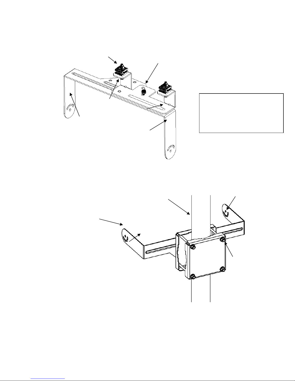
2. Mechanical Installation
Strand Clamp
Pivot Bolt
Housing
Bolt Hole
Up/Down Tilt
Locking
Bolt Slots
Figure 2-1 Yoke and Strand Mount Detail
Up/Down Tilt
Locking
Bolt Slots
Yoke
Figure 2-2 Yoke and Pipe Mount detail
Pivot
Locking
Bolt
Yoke
Mounting Pipe
1¼” through
2½”
Note that the Housing Bolts are
pre-torqued at the factory and
should not be tightened in the field.
Once the Up/down tilt is set lock it
in place with the up/down tilt
locking bolts.
Housing
Bolt Hole
Mounting
Bolts & Nuts
- 6 -
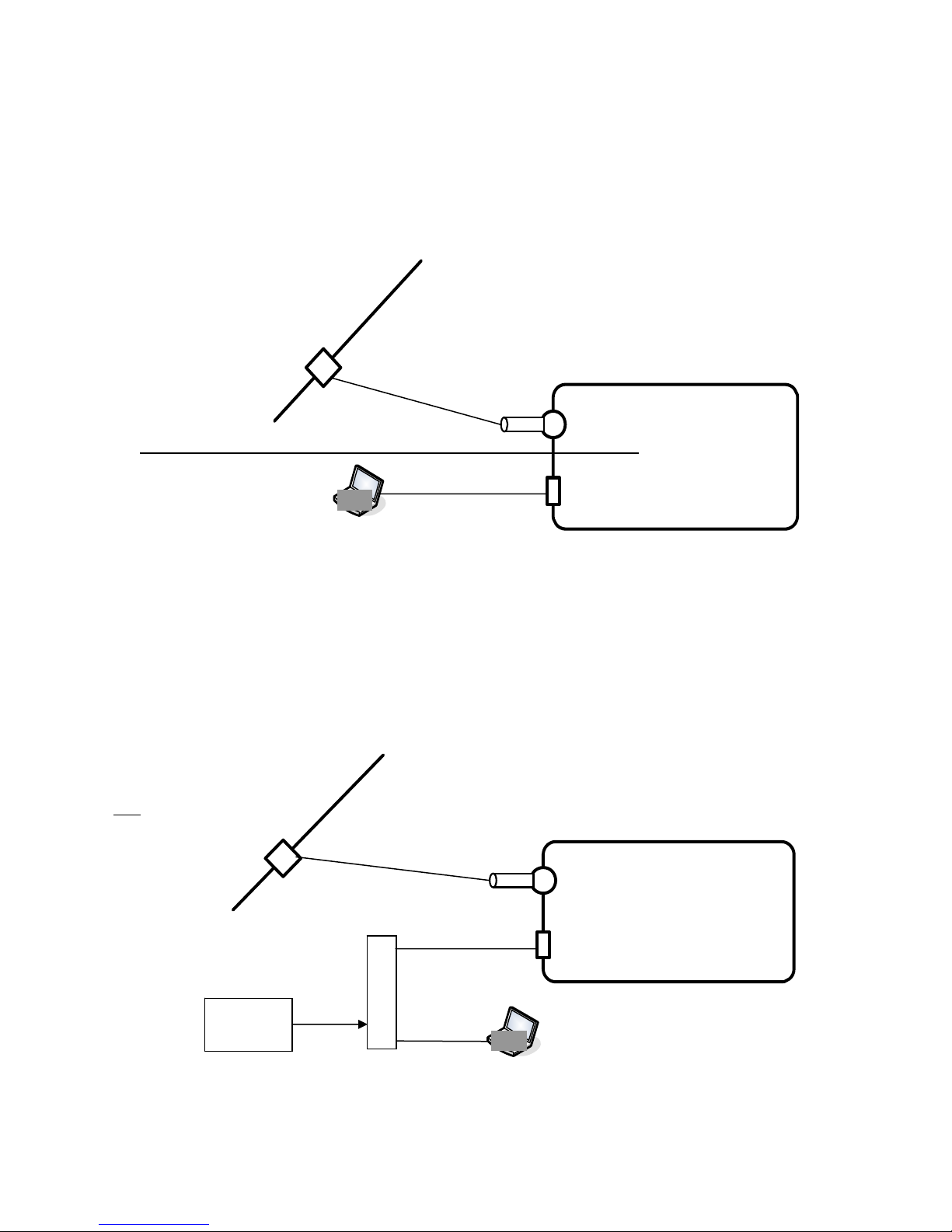
3. Powering Methods
3.1 Power from CATV System
Power-Passing Tap
CATV RF +
60-90 VAC
Surge
Protector
SMC8511
Ethernet
Port
Figure 3-1 Power from CATV System
When the SMC8511 is to be CATV line powered the tap must be power passing and the
attenuator value chosen to present the system standard levels to the internal cable modem. A
surge protector (furnished) provides protection from system power events. The laptop computer
utilized for configuration plugs into the Ethernet port.
3.2 Power from PoE Inserter
Non Power-Passing Tap
CATV RF
PoE
Surge
Protector
SMC8511
- 7 -
24 VDC
Ethernet
Port
Figure 3-2 Power from PoE Inserter

Above configuration (Fig 3-2) is particularly useful in a lab/shop environment where DOCSIS is
available but without power. A power injector
powers the SMC8511 through the Ethernet port.
2
fed with 24 VDC with at least 1 amp capacity
Note: Do not exceed 28VDC into the power
injector (no 48 VDC injectors), and do not use a power injector which places DC voltage on the
data leads.
See Section 3.4 for connections.
3.3 Power Output to PoE
When the SMC8511 Outdoor Cable Modem is powered from the CATV system through its Fconnector interface, it can optionally
power the external Ethernet device. The wiring /pin connections are given in Figure 3-3, below.
provide
24 VDC at 0.5 amps
from
the Ethernet port to
3.4 PoE Wiring
When the SMC8511 Outdoor Cable Modem is powered by means of PoE the connections are
given in Figure 3-3, below.
When the SMC8511 Outdoor Cable Modem is powered by 60-90 VAC CATV system power it can
optionally provide 24 VDC output to an attached Ethernet device. The connections for this
application are also as given in Figure 3-3, below.
Pin Input /
Output
1 Tx (+)
2 Tx (-)
3 Rx (+)
4 +V
5 +V
6 Rx (-)
7 GND
8 GND
Figure 3-3 PoE Wiring
Note that this PoE implementation differs from both the IEEE 802.3-2005 and draft IEEE 802.3af
standards.
use a power injector which places DC voltage on the data leads.
Do not exceed 28VDC into the power injector (no 48 VDC injectors), and do not
2
such as the SENAO PoE injector readily available on the Internet
- 8 -
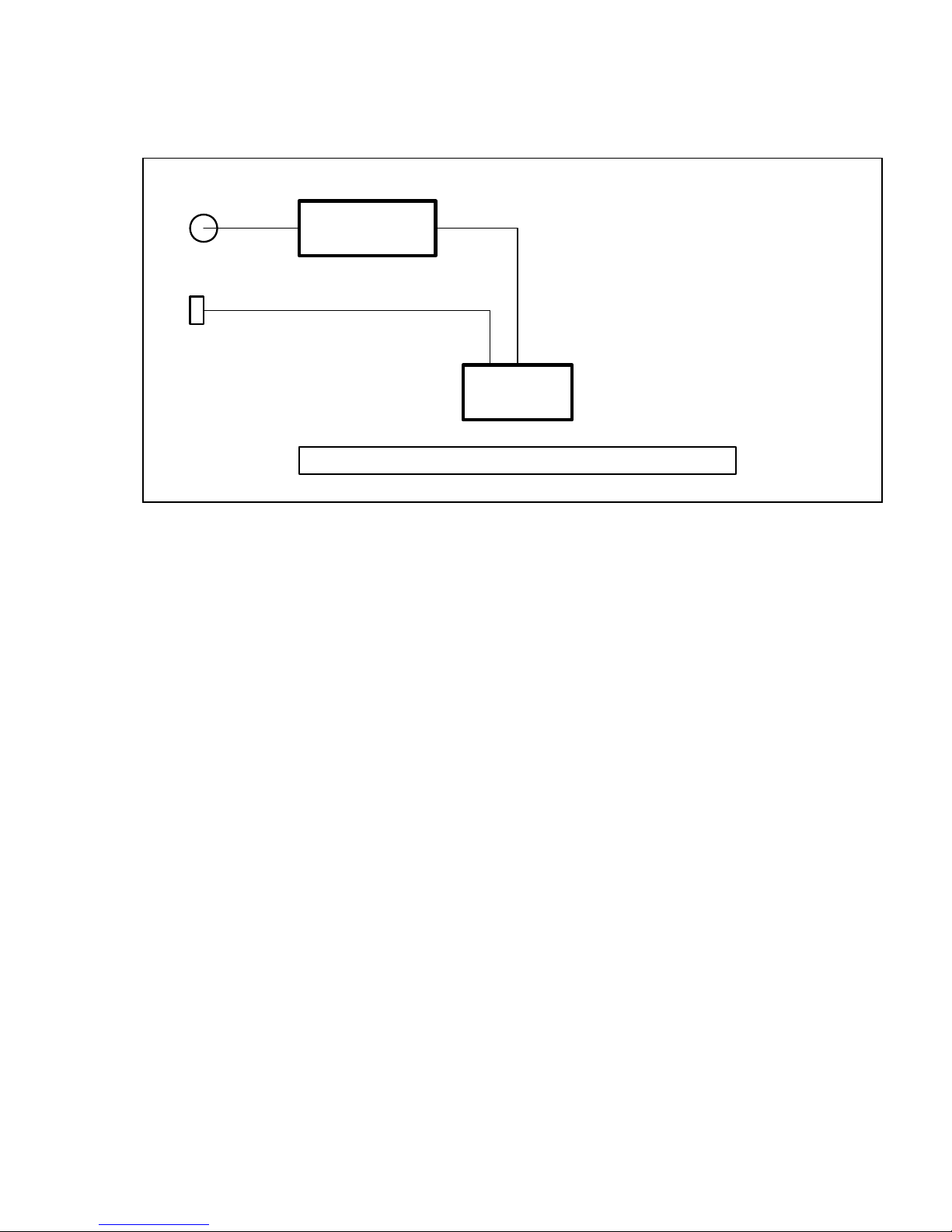
4. SMC8511 System Description
F Connector
Water Resistant
RJ45 Connector
DOCSIS 2.0
Cable Modem
Power Conversion and Distribution System
Ethernet
Switch
Figure 4-1 SMC8511 Simplified Block Diagram
4.1 SMC8511 Business Class Outdoor Cable Modem
The simplified block diagram of the SMC8511 Outdoor Cable Modem is as shown in Figure 4-1.
The SMC8511 includes a full-featured business class gateway DOCSIS modem.
In standard operation the internal DOCSIS 2.0 cable modem (CM) will obtain an IP
address from the head end DHCP server via the normal CM registration process as
required by the particular CATV system. Once the cable modem completes its
registration process with the DOCSIS head end, the DHCP client function in the
external Ethernet connected device will also obtain its IP address from the DOCSIS
head end DHCP.
- 9 -

5. SMC8511 Business Class DOCSIS Outdoor Cable Modem
5.1 Features
• Designed for commercial high speed Internet customers
• Integrated DOCSIS 2.0 cable modem
• One block of globally routable static IPs assigned to public LAN interface
• Static IP and block of public LAN IPs enabled via RIPv1/2
• Alternatively supports static IPs with static routes
• Remote management via CLI (TELNET), SNMP (DOCSIS defined and proprietary MIBs),
and GUI (HTTP and HTTPS)
• RADIUS, TACACS and TACACS+ login authentication
• Clear text router configuration files
• Downloadable router configuration files via TFTP
o A standard router configuration policy can be enforced via DOCSIS config file
vendor specific TLV
• DHCP server for static IP block
• Ethernet MAC address filtering
• Diagnostic tools
5.2 Out of Box Setup
• Physically mount the Outdoor Cable Modem as indicated in figures 2-1 or 2-2
• Provision the cable modem as any other standalone DOCSIS modem on the system
o The RF MAC for provisioning can be found on the side of the box or on the
sticker on the bottom of the unit.
• When in Router Mode the Outdoor Cable Modem CPE interface is enabled
• Provision the CPE interface as any other customer premise device connected to a
standard cable modem. In most cases, nothing needs to be done in the provisioning
system to enable the CPE Ethernet interface.
- 10 -

5.3 Defaults
The SMC8511 Outdoor Cable Modem (OCM) defaults to the following:
• Bridge Mode
• CPE / remote management interface – disabled
• Web server (GUI)
o RF interface – enabled on port 80 (HTTP) and 81 (HTTPS)
o CPE / remote management interface enabled on port 8080 (HTTP) and 8181
(HTTPS)
• Telnet
o RF interface enabled on port 23
o CPE / remote management interface enabled on port 2323
• LAN IP
o In Bridge Mode – 192.168.100.1
o In Router Mode – 20.20.20.1
• DHCP server – Enabled
- 11 -

5.4 Principal Operating Modes
5.4.1 Bridge Mode
When in Bridge Mode:
• The Outdoor Cable Modem (OCM) only requests an RF interface IP address.
• Logon to 192.168.100.1 (Ethernet interface) or RF interface IP to put OCM into Router Mode.
• CPE (Ethernet) interface, Static IP and RIP are disabled.
5.4.2 Router Mode
When in Router Mode:
• Default configuration – OCM requests both an RF interface IP (usually non-routable) and a
CPE / Remote Management interface IP (globally routable).
• By default, the CPE (Ethernet) interface is the RIP source IP.
• The Remote Management page defines ports on which the OCM listens for incoming
management requests to the CPE (Ethernet) interface.
• If ‘Use RF IP as the RIP source IP’ is selected, then the OCM will use RF IP as the RIP
source IP and will not pull a CPE (Ethernet) IP.
o LAN IP becomes CPE / Remote Management IP.
• If a static CPE (Ethernet) IP is configured, DNS values must be assigned. In this
configuration there are three IP addresses assigned to the OCM:
o RF
o CPE / Remote Management
o LAN
- 12 -
 Loading...