

SMC Networks EliteConnect SMC2891W-AG,EliteConnect SMC2890W-AG,2890W-AG,2891W-AG User Manual

USER GUIDE
SMC2890W-AG /
SMC2891W-AG
Elite Connect™
802.11a/g Outdoor Enterprise Access Point

EliteConnect
™
SMC2890W-AG and
SMC2891W-AG Universal 2.4GHz/
5GHz Wireless Dual-Band Outdoor
Access Point
The easy way to make all your network connections
20 Mason,
Irvine, CA 92618
Phone: (949) 679-8000
February 2007
Revision Number: R01
F1.0.0.1

Copyright
Information furnished by SMC Networks, Inc. (SMC) is believed to be accurate and reliable.
However, no responsibility is assumed by SMC for its use, nor for any infringements of patents
or other rights of third parties which may result from its use. No license is granted by
implication or otherwise under any patent or patent rights of SMC. SMC reserves the right to
change specifications at any time without notice.
Copyright © 2005 by
SMC Networks, Inc.
20 Mason
Irvine, CA 92618
All rights reserved.
Trademarks:
SMC is a registered trademark; and EliteConnect is a trademark of SMC Networks, Inc. Other
product and company names are trademarks or registered trademarks of their respective
holders.

Compliances
Federal Communication Commission Interference Statement
This equipment has been tested and found to comply with the limits for a Class B digital
device, pursuant to Part 15 of the FCC Rules. These limits are designed to provide
reasonable protection against harmful interference in a residential installation. This
equipment generates, uses and can radiate radio frequency energy and, if not installed
and used in accordance with the instructions, may cause harmful interference to radio
communications. However, there is no guarantee that interference will not occur in a
particular installation. If this equipment does cause harmful interference to radio or
television reception, which can be determined by turning the equipment off and on, the
user is encouraged to try to correct the interference by one of the following measures:
• Reorient or relocate the receiving antenna
• Increase the separation between the equipment and receiver
• Connect the equipment into an outlet on a circuit different from that to which the receiver
is connected
• Consult the dealer or an experienced radio/TV technician for help
FCC Caution: Any changes or modifications not expressly approved by the party
responsible for compliance could void the user’s authority to operate this equipment. This
device complies with Part 15 of the FCC Rules. Operation is subject to the following two
conditions: (1) This device may not cause harmful interference, and (2) this device must
accept any interference received, including interference that may cause undesired
operation.
IMPORTANT NOTE: FCC Radiation Exposure Statement
This equipment complies with FCC radiation exposure limits set forth for an uncontrolled
environment. This equipment should be installed and operated with a minimum distance
of 20 centimeters (8 inches) between the radiator and your body. This transmitter must
not be co-located or operating in conjunction with any other antenna or transmitter.
Wireless 5 GHz Band Statement:
As the access point can operate in the 5150-5250 MHz frequency band it is limited by the
FCC, Industry Canada and some other countries to indoor use only so as to reduce the
potential for harmful interference to co-channel Mobile Satellite systems.
High power radars are allocated as primary users (meaning they have priority) of the
5250-5350 MHz and 5650-5850 MHz bands. These radars could cause interference and/
or damage to the access point.
i

VCCI Notice
This is a class A product based on the standard of the Voluntary Control Council for
Interference by Information Technology Equipment (VCCI). If this equipment is used in a
domestic environment, radio disturbance may arise. When such trouble occurs, the user
may be required to take corrective actions.
EC Conformance Declaration
Marking by the above symbol indicates compliance with the Essential Requirements of
the R&TTE Directive of the European Union (1999/5/EC). This equipment meets the
following conformance standards:
• EN 60950 (IEC 60950) - Product Safety
• EN 301 893 - Technical requirements for 5 GHz radio equipment
• EN 300 328 - Technical requirements for 2.4 GHz radio equipment
• EN 301 489-1 / EN 301 489-17 - EMC requirements for radio equipment
Countries of Operation & Conditions of Use in the European
Community
This device is intended to be operated in all countries of the European Community.
Requirements for indoor vs. outdoor operation, license requirements and allowed
channels of operation apply in some countries as described below:
Note:
• This device requires that the user or installer properly enter the current country of
• This device will automatically limit the allowable channels determined by the current
The user must use the configuration utility provided with this product to ensure the
channels of operation are in conformance with the spectrum usage rules for
European Community countries as described below.
operation in the command line interface as described in the user guide, before operating
this device.
country of operation. Incorrectly entering the country of operation may result in illegal
operation and may cause harmful interference to other system. The user is obligated to
ensure the device is operating according to the channel limitations, indoor/outdoor
restrictions and license requirements for each European Community country as
described in this document.
ii

• This device employs a radar detection feature required for European Community
operation in the 5 GHz band. This feature is automatically enabled when the country of
operation is correctly configured for any European Community country. The presence of
nearby radar operation may result in temporary interruption of operation of this device.
The radar detection feature will automatically restart operation on a channel free of
radar.
• The 5 GHz Turbo Mode feature is not allowed for operation in any European Community
country. The current setting for this feature is found in the 5 GHz 802.11a Radio Settings
Window as described in the user guide.
• The 5 GHz radio's Auto Channel Select setting described in the user guide must always
remain enabled to ensure that automatic 5 GHz channel selection complies with
European requirements. The current setting for this feature is found in the 5 GHz
802.11a Radio Settings Window as described in the user guide.
• This device may be operated indoors or outdoors in all countries of the European
Community using the 2.4 GHz band: Channels 1 - 13, except where noted below.
- In Italy the end-user must apply for a license from the national spectrum authority to
operate this device outdoors.
- In Belgium outdoor operation is only permitted using the 2.46 - 2.4835 GHz band:
Channel 13.
- In France outdoor operation is only permitted using the 2.4 - 2.454 GHz band:
Channels 1 - 7
Operation Using 5 GHz Channels in the European Community
The user/installer must use the provided configuration utility to check the current channel
of operation and make necessary configuration changes to ensure operation occurs in
conformance with European National spectrum usage laws as described below and
elsewhere in this document.
Allowed 5GHz Channels in Each European Community Country
Allowed Frequency Bands Allowed Channel Numbers Countries
5.15 - 5.25 GHz* 36, 40, 44, 48 Austria, Belgium
5.15 - 5.35 GHz* 36, 40, 44, 48, 52, 56, 60, 64 France, Switzerland,
Liechtenstein
5.15 - 5.35* & 5.470 - 5.725
GHz
36, 40, 44, 48, 52, 56, 60, 64,
100, 104, 108, 112, 116, 120,
124, 128, 132, 136, 140
Denmark, Finland,
Germany, Iceland,
Ireland, Italy,
Luxembourg,
Netherlands, Norway,
Portugal, Spain,
Sweden, U.K.
iii

Allowed 5GHz Channels in Each European Community Country
Allowed Frequency Bands Allowed Channel Numbers Countries
5 GHz Operation Not Allowed None Greece
* Outdoor operation is not allowed using 5.15-5.35 GHz bands (Channels 36 - 64).
Channels 36 - 64 are currently not available for use.
Safety Compliance
Power Cord Safety
Please read the following safety information carefully before installing the device:
Warning:
• The unit must be connected to an earthed (grounded) outlet to comply with international
safety standards.
• Do not connect the unit to an A.C. outlet (power supply) without an earth (ground)
connection.
• The appliance coupler (the connector to the unit and not the wall plug) must have a
configuration for mating with an EN 60320/IEC 320 appliance inlet.
• The socket outlet must be near to the unit and easily accessible. You can only remove
power from the unit by disconnecting the power cord from the outlet.
• This unit operates under SELV (Safety Extra Low Voltage) conditions according to IEC
60950. The conditions are only maintained if the equipment to which it is connected also
operates under SELV conditions.
France and Peru only
This unit cannot be powered from IT
must be powered by 230 V (2P+T) via an isolation transformer ratio 1:1, with the
secondary connection point labelled Neutral, connected directly to earth (ground).
†
Impédance à la terre
Important! Before making connections, make sure you have the correct cord set. Check
it (read the label on the cable) against the following:
Installation and removal of the unit must be carried out by qualified personnel
only.
†
supplies. If your supplies are of IT type, this unit
iv

Power Cord Set
U.S.A. and
Canada
Denmark The supply plug must comply with Section 107-2-D1, Standard
Switzerland The supply plug must comply with SEV/ASE 1011.
U.K. The supply plug must comply with BS1363 (3-pin 13 A) and be
Europe The supply plug must comply with CEE7/7 (“SCHUKO”).
The cord set must be UL-approved and CSA certified.
The minimum specifications for the flexible cord are:
- No. 18 AWG - not longer than 2 meters, or 16 AWG.
- Type SV or SJ
- 3-conductor
The cord set must have a rated current capacity of at least 10 A
The attachment plug must be an earth-grounding type with
NEMA 5-15P (15 A, 125 V) or NEMA 6-15P (15 A, 250 V)
configuration.
DK2-1a or DK2-5a.
fitted with a 5 A fuse which complies with BS1362.
The mains cord must be <HAR> or <BASEC> marked and be of
type HO3VVF3GO.75 (minimum).
The mains cord must be <HAR> or <BASEC> marked and be of
type HO3VVF3GO.75 (minimum).
IEC-320 receptacle.
Veuillez lire à fond l'information de la sécurité suivante avant d'installer l’appareil:
AVERTISSEMENT: L’installation et la dépose de ce groupe doivent être confiés à un
personnel qualifié.
• Ne branchez pas votre appareil sur une prise secteur (alimentation électrique) lorsqu'il
n'y a pas de connexion de mise à la terre (mise à la masse).
• Vous devez raccorder ce groupe à une sortie mise à la terre (mise à la masse) afin de
respecter les normes internationales de sécurité.
• Le coupleur d’appareil (le connecteur du groupe et non pas la prise murale) doit
respecter une configuration qui permet un branchement sur une entrée d’appareil EN
60320/IEC 320.
• La prise secteur doit se trouver à proximité de l’appareil et son accès doit être facile.
Vous ne pouvez mettre l’appareil hors circuit qu’en débranchant son cordon électrique
au niveau de cette prise.
v

• L’appareil fonctionne à une tension extrêmement basse de sécurité qui est conforme à
la norme IEC 60950. Ces conditions ne sont maintenues que si l’équipement auquel il
est raccordé fonctionne dans les mêmes conditions.
France et Pérou uniquement:
Ce groupe ne peut pas être alimenté par un dispositif à impédance à la terre. Si vos
alimentations sont du type impédance à la terre, ce groupe doit être alimenté par une
tension de 230 V (2 P+T) par le biais d’un transformateur d’isolement à rapport 1:1, avec
un point secondaire de connexion portant l’appellation Neutre et avec raccordement
direct à la terre (masse).
Cordon électrique - Il doit être agréé dans le pays d’utilisation
Etats-Unis et
Canada:
Danemark: La prise mâle d’alimentation doit respecter la section 107-2 D1
Suisse: La prise mâle d’alimentation doit respecter la norme SEV/ASE
Europe La prise secteur doit être conforme aux normes CEE 7/7
Le cordon doit avoir reçu l’homologation des UL et un certificat
de la CSA.
Les spécifications minimales pour un cable flexible sont AWG
No. 18, ouAWG No. 16 pour un cable de longueur inférieure à 2
mètres.
- type SV ou SJ
- 3 conducteurs
Le cordon doit être en mesure d’acheminer un courant nominal
d’au moins 10 A.
La prise femelle de branchement doit être du type à mise à la
terre (mise à la masse) et respecter la configuration NEMA
5-15P (15 A, 125 V) ou NEMA 6-15P (15 A, 250 V).
de la norme DK2 1a ou DK2 5a.
1011.
(“SCHUKO”)
LE cordon secteur doit porter la mention <HAR> ou <BASEC> et
doit être de type HO3VVF3GO.75 (minimum).
vi

Bitte unbedingt vor dem Einbauen des Geräts die folgenden
Sicherheitsanweisungen durchlesen
WARNUNG: Die Installation und der Ausbau des Geräts darf nur durch Fachpersonal
erfolgen.
• Das Gerät sollte nicht an eine ungeerdete Wechselstromsteckdose angeschlossen
werden.
• Das Gerät muß an eine geerdete Steckdose angeschlossen werden, welche die
internationalen Sicherheitsnormen erfüllt.
• Der Gerätestecker (der Anschluß an das Gerät, nicht der Wandsteckdosenstecker) muß
einen gemäß EN 60320/IEC 320 konfigurierten Geräteeingang haben.
• Die Netzsteckdose muß in der Nähe des Geräts und leicht zugänglich sein. Die
Stromversorgung des Geräts kann nur durch Herausziehen des Gerätenetzkabels aus
der Netzsteckdose unterbrochen werden.
• Der Betrieb dieses Geräts erfolgt unter den SELV-Bedingungen
(Sicherheitskleinstspannung) gemäß IEC 60950. Diese Bedingungen sind nur gegeben,
wenn auch die an das Gerät angeschlossenen Geräte unter SELV-Bedingungen
betrieben werden.
(Germany):
vii

Stromkabel. Dies muss von dem Land, in dem es benutzt wird geprüft werden:
U.S.A und Canada Der Cord muß das UL gepruft und war das CSA beglaubigt.
Das Minimum spezifikation fur der Cord sind:
- Nu. 18 AWG - nicht mehr als 2 meter, oder 16 AWG.
- Der typ SV oder SJ
- 3-Leiter
Der Cord muß haben eine strombelastbarkeit aus wenigstens
10 A
Dieser Stromstecker muß hat einer erdschluss mit der typ
NEMA 5-15P (15A, 125V) oder NEMA 6-15P (15A, 250V)
konfiguration.
Danemark Dieser Stromstecker muß die ebene 107-2-D1, der standard
DK2-1a oder DK2-5a Bestimmungen einhalten.
Schweiz Dieser Stromstecker muß die SEV/ASE 1011Bestimmungen
einhalten.
Europe Das Netzkabel muß vom Typ HO3VVF3GO.75
(Mindestanforderung) sein und die Aufschrift <HAR> oder
<BASEC> tragen.
Der Netzstecker muß die Norm CEE 7/7 erfüllen (”SCHUKO”).
viii

Table of Contents
Chapter 1: Introduction 1-1
Radio Characteristics 1-1
Package Checklist 1-2
Hardware Description 1-2
LED Indicators 1-3
Integrated High-Gain Antenna 1-5
External Antenna Options 1-5
Ethernet Port 1-6
Power Injector Module 1-6
Grounding Point 1-7
Water Tight Test Point 1-7
Wall- and Pole-Mounting Bracket Kit 1-7
System Configuration 1-8
Features and Benefits 1-8
Chapter 2: Network Configuration 2-1
Access Point Topologies 2-1
Infrastructure Wireless LAN 2-2
Infrastructure Wireless LAN for Roaming Wireless PCs 2-3
Bridge Link Topologies 2-4
Point-to-Point Configuration 2-4
Point-to-Multipoint Configuration 2-5
Chapter 3: Bridge Link Planning 3-1
Data Rates 3-1
Radio Path Planning 3-1
Antenna Height 3-2
Antenna Position and Orientation 3-4
Radio Interference 3-5
Weather Conditions 3-5
Ethernet Cabling 3-5
Grounding 3-6
Chapte r 4: Hardware Installation 4-1
Testing Basic Link Operation 4-1
Mount the Unit 4- 1
ix

Contents
Mounting to a Wall 4-4
Connect External Antennas 4-5
Connect Cables to the Unit 4-6
Connect the Power Injector 4-7
Align Antennas 4-8
Chapter 5: Initial Configuration 5-1
Initial Setup through the CLI 5-1
Required Connections 5-1
Initial Configuration Steps 5-2
Logging In 5-3
Chapter 6: System Configuration 6-1
Advanced Confi gur atio n 6-2
System Identification 6-3
TCP / IP Settings 6-5
RADIUS 6-7
SSH Settings 6-11
Authentication 6-12
Filter Control 6-17
VLAN 6-19
WDS Settings 6-21
AP Management 6-27
Administration 6-28
System Log 6-33
RSSI 6-37
SNMP 6-40
Configuring SNMP and Trap Message Parameters 6-41
Configuring SNMPv3 Users 6-46
Configuring SNMPv3 Trap Filters 6-48
Configuring SNMPv3 Targets 6-50
Radio Interface 6- 51
Radio Settings A (802.11a) 6-53
Radio Settings G (802.11g) 6-68
Security 6-70
Status Information 6-88
Access Po int Status 6-88
Station Status 6-91
Event Logs 6-93
STP Status 6-95
x

Contents
Chapter 7: Command Line I nterfac e 7-1
Using the Command Line Interface 7-1
Accessing the CLI 7-1
Console Connection 7-1
Telnet Connection 7-1
Entering Commands 7-2
Keywords and Arguments 7-2
Minimum Abbreviation 7-2
Command Completion 7-3
Getting Help on Commands 7-3
Partial Keyword Lookup 7-4
Negating the Effect of Commands 7-4
Using Command History 7-4
Understanding Command Modes 7-4
Exec Commands 7-5
Configuration Commands 7-5
Command Line Processing 7-6
Command Groups 7-6
General Commands 7-7
configure 7-8
end 7-8
exit 7-8
ping 7-9
reset 7-10
show history 7-10
show line 7-11
System Management Commands 7-11
country 7-12
prompt 7-14
system name 7-14
username 7-15
password 7-15
ip ssh-server enable 7-16
ip ssh-server port 7-16
ip telnet-server enable 7-17
ip http port 7-17
ip http server 7-18
ip http session-time out 7-18
ip https port 7-19
ip https server 7-1 9
web-redirect 7-20
APmgmtIP 7-21
APmgmtUI 7-22
show apmanagement 7-22
xi

Contents
show system 7-24
show version 7-25
show config 7-25
show hardware 7-29
System Logging Commands 7-29
logging on 7-30
logging host 7-30
logging console 7-31
logging level 7-31
loggin g facility-type 7-32
logging clear 7-33
show logging 7-33
show event-log 7-34
System Clock Commands 7-34
sntp-server ip 7-35
sntp-server enable 7-35
sntp-server date-time 7-36
sntp-server daylight-saving 7-37
sntp-server timezone 7-37
show sntp 7-38
DHCP Relay Commands 7-39
dhcp-relay enable 7-39
dhcp-relay 7-40
show dhcp-relay 7-40
SNMP Commands 7-41
snmp-server community 7-42
snmp-server contact 7-42
snmp-server location 7-43
snmp-server enable server 7-43
snmp-server host 7-44
snmp-server trap 7-45
snmp-server engine-id 7-46
snmp-server user 7-47
snmp-server targets 7-49
snmp-server filter 7-50
snmp-server filter-assignments 7-51
show snmp groups 7-51
show snmp users 7-52
show snmp group-assignments 7-52
show snmp target 7-53
show snmp filter 7-53
show snmp filter-assignments 7-54
show snmp 7-55
Flash/File Commands 7-56
bootfile 7-56
xii

Contents
copy 7-57
delete 7-58
dir 7-59
show bootfile 7-59
RADIUS Client 7-60
radius-server address 7-60
radius-server port 7-61
radius-server key 7-61
radius-server retransmit 7-62
radius-server timeout 7-62
radius-server port-accounting 7-63
radius-server timeout-interim 7-63
radius-server radius-mac-format 7-64
radius-server vlan-format 7-64
show radius 7-65
802.1X A uthentication 7-66
802.1x 7-66
802.1x broadcast-key-refresh-rate 7-67
802.1x se ssion-key- refresh-rate 7-68
802.1x session-timeout 7-68
802.1x-supplicant enable 7-69
802.1x-supplicant user 7-69
show authentication 7-70
MAC Address Authentication 7-71
address filter default 7-71
address filter entry 7-72
address filter delete 7-72
mac-authentication server 7-73
mac-authentication session-timeout 7-73
Filtering Commands 7-74
filter local-bridge 7-75
filter ap-manage 7-75
filter uplink enable 7-76
filter uplink 7-76
filter ethernet-type enable 7-76
filter ethernet-type protocol 7-77
show filters 7-78
WDS Bridge Commands 7-78
bridge mode 7-79
bridge role (WDS) 7-79
bridge channel-auto-sync 7-80
bridge-link parent 7-80
bridge-link child 7-81
bridge dynamic-entry age-time 7-82
show bridge aging-time 7-82
xiii

Contents
show bridge filter-entry 7-83
show bridge link 7-83
Spanning Tree Commands 7-85
bridge stp enable 7-85
bridge stp forwarding-delay 7-86
bridge stp hello-time 7-86
bridge stp max-age 7-87
bridge stp priority 7-87
bridge-link path-cost 7-88
bridge-link port-priority 7-88
show bridge stp 7-89
Ethernet Interface Commands 7-90
interface ethernet 7-90
dns server 7-91
ip address 7-91
ip dhcp 7-92
speed-duplex 7-93
shutdown 7-94
show interface ethernet 7-94
Wireless Interfac e Comm and s 7-95
interface wireless 7-97
vap 7-97
speed 7-98
turbo 7-98
multicast-data-rate 7-99
channel 7-100
transmit-power 7-100
radio-mode 7-101
preamble 7-102
antenna control 7-103
antenna id 7-103
antenna location 7-104
beacon-interval 7-105
dtim-period 7-105
fragmentation-length 7-106
rts-threshold 7-107
super-a 7-108
super-g 7-108
description 7-109
ssid 7-109
closed-system 7-110
max-association 7-110
assoc-timeout-interval 7-111
auth-timeout-value 7-111
shutdown 7-111
xiv

Contents
show interface wireless 7-113
show station 7-115
Rogue AP Detection Commands 7-116
rogue-ap enable 7-116
rogue-ap authenticate 7-117
rogue-ap duration 7-118
rogue-ap interval 7-118
rogue-ap scan 7-119
show rogue-ap 7-120
Wireless Security Comm and s 7-120
auth 7-121
encryption 7-123
key 7-124
transmit-key 7-125
cipher-suite 7-126
mic_mode 7-127
wpa-pre-shared-key 7-128
pmksa-lifetime 7-128
pre-authentication 7-129
Link Integrity Commands 7-130
link-integrity ping-detect 7-131
link-integrity ping-host 7-131
link-integrity ping-interval 7-132
link-integrity ping-fail-retry 7-132
link-integrity ethernet-detect 7-132
show link-integrity 7-133
IAPP Commands 7-134
iapp 7-134
VLAN Commands 7-135
vlan 7-135
management-vlanid 7-136
vlan-id 7-136
WMM Commands 7-137
wmm 7-138
wmm-acknowledge-policy 7-138
wmmparam 7-139
Appendix A: Troubleshooting A-1
Appendix B: Cables and Pinouts B-1
Twisted-Pair Cable Assignments B-1
10/100BASE-TX Pin Assignments B-1
Straight-Through Wiring B-2
xv

Contents
Crossover Wiring B-3
8-Pin DIN Connector Pinout B-3
8-Pin DIN to RJ-45 Cable Wiring B-4
Appendix C: Specifications C-1
General Specifications C-1
Sensitivity C-4
Transmit Power C-5
Appendix D: Montieren der Bridge D-1
Verwenden der Halterung für Mastmontage D-1
Verwenden der Halterung für Wandmontage D-3
Anschließen der externen Antennen D-5
Anschließen der Kabel an das Gerät D-6
Anschließen des PoE Inject ors D-7
Glossary
Index
xvi

Chapter 1: Introduction
The Dual-band Outdo or Acc ess Point / Bridge system con si sts of tw o m odels that
provide point-to- poi nt or poi nt - to -multipoint bridge links between remote E thernet
LANs, and wireles s access point services for clients in the local LAN ar ea:
• SMC2891W-AG – Includes an integrated high-gain antenna for the 802.11a radio
and is designed to operate as a “bridge node” in point-to-multipoint configurations,
or provide a high-speed point-to-point wireless link between two sites that can be
up to 15.4 km (9.6 miles) apart. The 802.11b/g radio requires an external antenna
option.
• SMC2890W-AG – Provides only ex ternal antenna options and i s de si gned to
operate as the “root br id ge” in poi nt-to-multipoint conf i gur at ions, supporting
wireless bridge connections to as many as six units.
Note: Both models can be set to operate in either “root bridge” or “bridge node” mode.
Each model is hous ed in a weatherproof encl os ur e f or mounting outdoors and
includes its own brackets for attaching to a wall, pole, radio mast, or tower structure.
The unit is powered th ro ugh its Ethernet cable connec tion from a power injector
module that is installe d indoors.
The wireless bridge system offers a fast, reliable, and cost-effective solution for
connectivity bet ween remote Ethernet w ired LANs or to provide Inte rn et access to
an isolated site. The system is also easy to in stall and operate, ideal for situ at i ons
where a wired link may be difficult or expensive to deploy. The wireless bridge
connection prov id es data rates of up to 108 Mbps.
In addition, both wireless bridge mode ls offer full network ma na gem e nt capabilities
through an easy -to- use web interface, a com m and-line interface , an d support for
Simple Network Managemen t Protocol (SNMP) t ools.
Radio Characteristics
The IEEE 802.11a and 802.11g standards use a radi o m odulation techniq ue kn ow n
as Orthogonal F re quency Division Multi plexing (OFDM), and a shared collision
domain (CSMA/ CA ) . Th e 802 . 11a standard operates in the 5 GH z U n licensed
National Informat i on Infrastructure (UN I I) band, and the 802.11g standard in the
2.4 GHz band.
IEEE 802.11g includes backward compatibi lity w i th th e IE EE 802.11b standard.
IEEE 802.11b also operates at 2.4 GHz, but uses D irec t Se qu ence Spread
Spectrum (DSSS) and Complem enta ry Code Keying (CCK) modul at ion t echnology
to achieve a communication rate of up to 11 Mbps.
The wireless bridge pro vi des a 54 Mbps half-duplex con nection for each active
channel (up to 108 M bps in turbo mode on the 802.11a interface).
1-1
1
Introduction
Package Checklist
The Dual-band Outdo or Access Point / Bridge packag e incl udes:
• One Wireless Dual-band Access Point (SMC 2890W-AG or SMC2891W-AG)
• One Category 5e network PoE cable, length 98 ft (30 m )
• One power injector module and power cord 5.9 ft (1.8 m)
• One RS232 console cable 5.9ft (1.8 m)
• Outdoor pole- and wall- m ounting bracket kit
• User Guide CD
Inform your deal er if the re are any incorrect, missing or damaged parts. If possible,
retain the carton, including the original packing materials. Use them again to repack
the product in case t her e i s a need to return it.
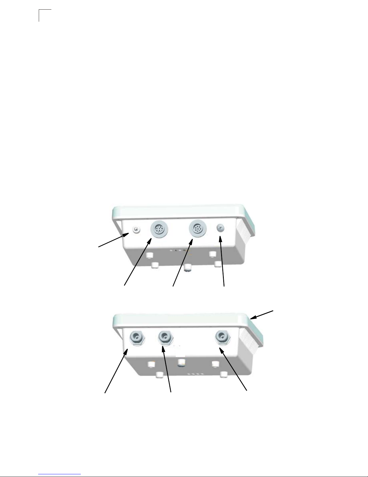
Hardware Description
Bottom View
(both models)
Console Port
CoverAttachment
Top View
(SMC2891W-AG)
Console Port
Ethernet/PoE
Connector
Water-Tight Test Point
(DO NOT REMOVE)
Integrated Anten na
N-Type External
Antenna Connector
(2.4 GHz)
1-2
N-Type External
Antenna Conne ctor
(5 GHz)
N-Type Exter nal
Antenna Connect or
(2.4 GHz)
Top View
(SMC2890W-AG)
LED Indicators
1
N-Type External
Antenna Connector
(2.4 GHz)
Right Antenna
N-Type Exter nal
Antenna Connecto r
(5 GHz)
Right Antenna
N-Type Exter nal
Antenna Connect or
(5 GHz)
Left Antenna
N-Type External
Antenna Connector
(2.4 GHz)
Left Antenna
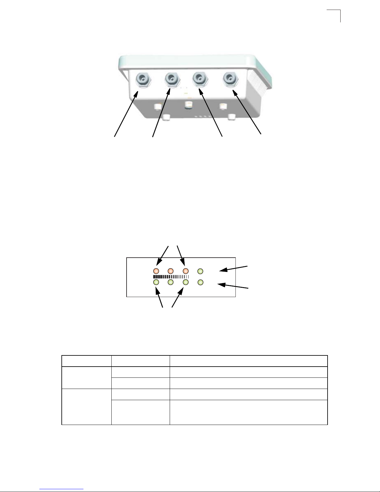
LED Indicators
The access point i ncludes eight status LED in dicators, as indicated i n th e fo l low i ng
figure.
802.11b/g Wireless
Link/Activity
11b/g
11a
802.11a Wireless
Link/Activity
Power
Link
Power
Ethernet
Link/Activity
The following table describes the system status LED s.
LED Status Description
Power On Gree n Indicates that the system is working normally.
On Amber Indicates a system reset.
Link On Green Indicates a valid 10/100 Mbps Ethernet cable link.
Flashing Green Indicates that the access point is transmitting or receiving data
on a 10/100 Mbps Ethernet LAN. Flashing rate is proportional
to network activity.
1-3

1
Introduction
The 11a and 11b/g LEDs operate in two display mo des, which are configur able
through the management interface. The RSSI m ode is for aligning antennas in a
bridge link. The AP mod e is for indi cating data traffic rates.
The following table desc ribes the wireless status LED s i n AP m od e.
LED Status Description
11a
(three LEDs)
11b/g
(three LEDs)
Off No signal detected or the 802.11a radio is disabled.
Slow Flashing Green The 802.11a radio is enabled with a low level of network
activity.
Fast Flashing Green Indicates a medium level of network activity.
On Green Indicates a high level of network activity.
Off No signal detected or the 802.11b/g radio is disabled.
Slow Flashing Green The 802.11b/g radio is enabled with a low level of network
activity.
Fast Flashing Green Indicates a medium level of network activity.
On Green Indicates a high level of network activity.
The following table desc ribes the wireless status LED s i n RSSI m ode.
LED Status Description
11a
(three LEDs)
Off No signal detected or the 802.11a radio is disabled.
Slow Flashing Green The 802.11a radio is enabled with a low level signal.
Fast Flashing Green Indicates a medium level signal.
On Green Indicates a high level signal.
11b/g
(three LEDs)
Off No signal detected or the 802.11b/g radio is disabled.
Slow Flashing Green The 802.11b/g radio is enabled with a low level signal.
Fast Flashing Green Indicates a medium level signal.
On Green Indicates a high level signal.
1-4
1
Introduction
Ethernet Port
The wireless bridge has one 10BAS E-T /1 00 BASE-TX 8-pin DIN port that connects
to the power injector mo dul e u si ng t he inc luded Ethernet cable. The Ether net port
connection prov id es power to the wireless bridge as well as a data link to th e l ocal
network.
The wireless bridge appears as an Ethernet nod e and performs a bridging fun ct i on
by moving packets from the wired LAN to the remote end of the wireless bridge link.
Note: The power injector module does not support Power over Ethernet (PoE) based on
the IEEE 802.3af standard. The wireless bridge unit must always be powered on
by being connected to the power injector module.
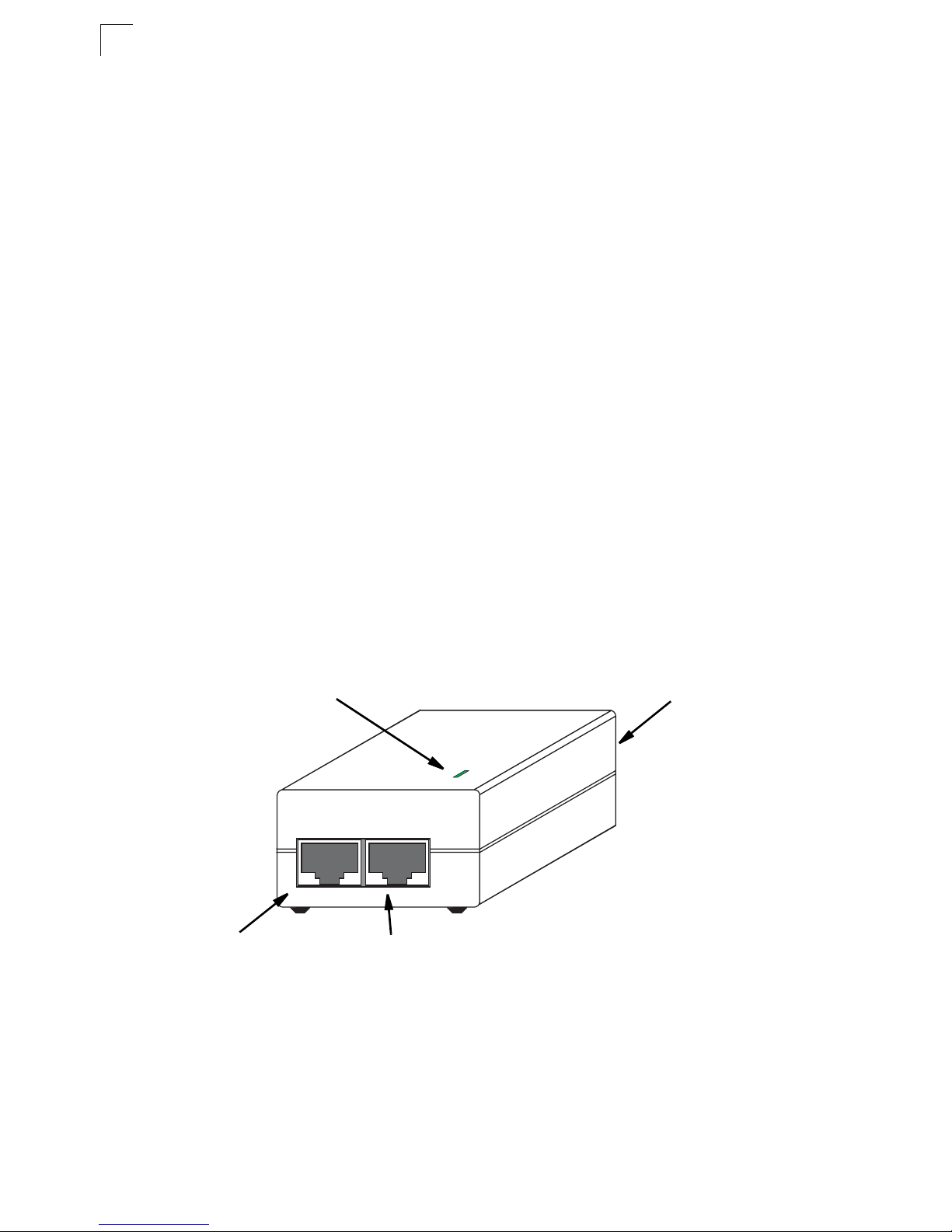
Power Injector Module
The wire l ess bridge receiv es power th rough its network cable conn ection using
power-over-Ethernet technology. A power injector module is included in the wireless
bridge package and pr ovides two RJ-45 Ether net ports, one for connecting t o t he
wireless bridge (Output), and the other for connecting to a local LAN s w itc h (Input).
The Input port uses an MDI (i.e., internal straight-through) pin configuration. You can
therefore use straight-through twisted-pair cable to connect this port to most network
interconnectio n devices such as a switc h or router that provide MDI -X ports.
However, when connecting t he ac cess point to a workstati on or ot her device that
does not have MDI-X ports, you must use cr ossover twisted-pair cabl e.
Ethernet from
Local Network
LED Indicator
Input Output
Ethernet and Power
to Wireless Bridge
AC Power Socket
(Hidden)
The wireless bridge does not have a power sw it ch. It is powered on when its
Ethernet port is connected to the power inj ect or m odule, and the power inj ect o r
module is connec ted t o an AC power source. The pow er injector includes one LED
indicator that turns on when AC power is appl i ed.
1-6

Grounding Point
The power injecto r module automaticall y ad ju sts to any AC voltage between
100-240 volts at 50 or 60 Hz. No voltage range settings are required.
Warning: The power injector module is designed for indoor use only. Never mount
the power injector outside with the wireless br id ge uni t.
Grounding Point
Even though the wir el ess bridge includes its ow n built-in lightning protect i on, it is
important that the unit is pro per l y co nnected to ground. A grounding screw is
provided for attaching a gr ound wire to the unit.
Water Tight Test Point
Caution: Do no remove or loosen this sc re w. Doing so could lea d t o dam age of the
unit.
1
Wall- and Pole-Mounting Bracket Kit
The wireless bridge includes a bracket ki t tha t ca n be used to mount the brid ge t o a
wall, pole, radio m ast , or part of a to w er st ru ct ur e.
1-7
1
Introduction
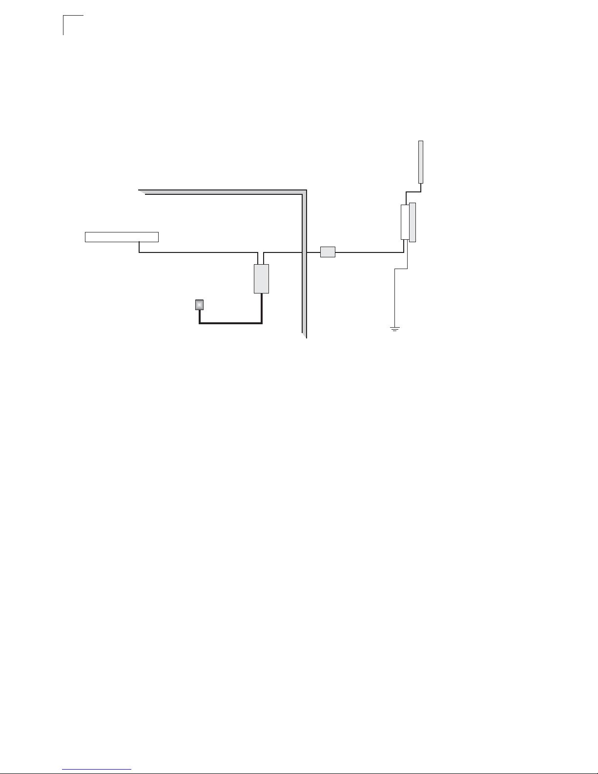
System Configuration
At each location w her e a un i t is install ed, it must be connected t o t he local network
using the power in je ctor module. The followi ng f ig ur e i llus trat es the system
component co nnections.
External Antenna
RF Coaxial Cable
Wireless Bridge Unit
Ground Wire
LAN Switch
Ethernet Cable
AC Power
Power
Injector
Indoor Outdoor
Ethernet
Cable
Lightning
Arrestor
Features and Benefits
• SMC2891W-AG units support a 5 GHz point-to-point wireless link up 15.4 km (at
6 Mbps data rate) using integrated high-gai n 17 dBi antennas
• SMC2890W-AG units su pport 5 GHz point-to- m ul ti poi nt lin ks using various
external antenna options
• Both SMC2890W-AG and SMC2 891W-AG units also support acc ess point
services for the 5 GHz and 2.4 GHz radios using various external antenna options
• Maximum data rate up to 108 Mbps on the 802.11a (5 GH z) radio
• Outdoor weatherproo f de si gn
• IEEE 802.11a and 802.11b/g compliant
• Local network connecti on via 10/100 Mbps Ether net port
• Powered through its Ethe rn et cab le con nection to the power injec to r module
• Includes wall- and pole -mount bracket
• Security through 64/128/ 152-bit Wired Equivalent Protection (WE P ) o r 12 8- bi t
Advanced Encryp t ion St and ar d (AES) encryption
• Scans all available channels and selects the best channel and data rate based on
the signal-to-n oise r at i o
• Manageable through an easy-to-use web -b ro w ser interface, comm and line (via
Telnet), or SNMP network management tools
1-8

Chapter 2: Network Configuration
The Dual-band Outdo or Acc ess Point / Bridge system pro vides access point and
bridging service s t hro ugh either the 5 GHz or 2.4 G H z radio interfaces.
The wireless bridge units can be used just as nor m al 802.11a/b/g access poi nts
connected to a local wired LAN, providing connectivity and roaming services for
wireless clients in an ou tdoor ar ea. Units can also be used pu re l y as bridges
connecting rem ote LANs. Alternatively, you can employ both access point and
bridging functions to get her, offering a flexible and convenient wireless sol ut ion f or
many applications.
This chapter desc ribe s t he r ol e of Dual - band Outdoor Access Point / Bri dge in
various wirele ss net w or k configurations.
Access Point Topologies
Operat ing as an outdoor ac cess poin t , the unit is deplo yed in an int egrated
configuration wi t h w ired Ethernet LANs, providing network a ccess to wireless
stations in the wireles s coverage area.
The access point’s radios can support these m od es:
• Infrastructure wireless LAN
• Infrastructure wireless LAN with roaming
• Point-to-point bridge link
• Point-to-multi point bridge links
The 802.11b and 802.11g frequency band, w hi ch operates at 2.4 GHz, can easily
encounter inte rfer ence from other 2.4 G Hz devices, such as oth er 802.11b or g
wireless devices, cordless phones and microwave ovens. If you experience poor
wireless LAN perf ormance, try the follow i ng measures:
• Limit any possible sources of radio interference within the service area
• Increase the distance between neighboring ac cess points
• Increase the channe l se parati on of n ei ghboring access poin ts (e.g ., up to 3
channels of separat ion f or 802.11b or up to 5 channels for 802.11g)
2-1
2
Network Configuration
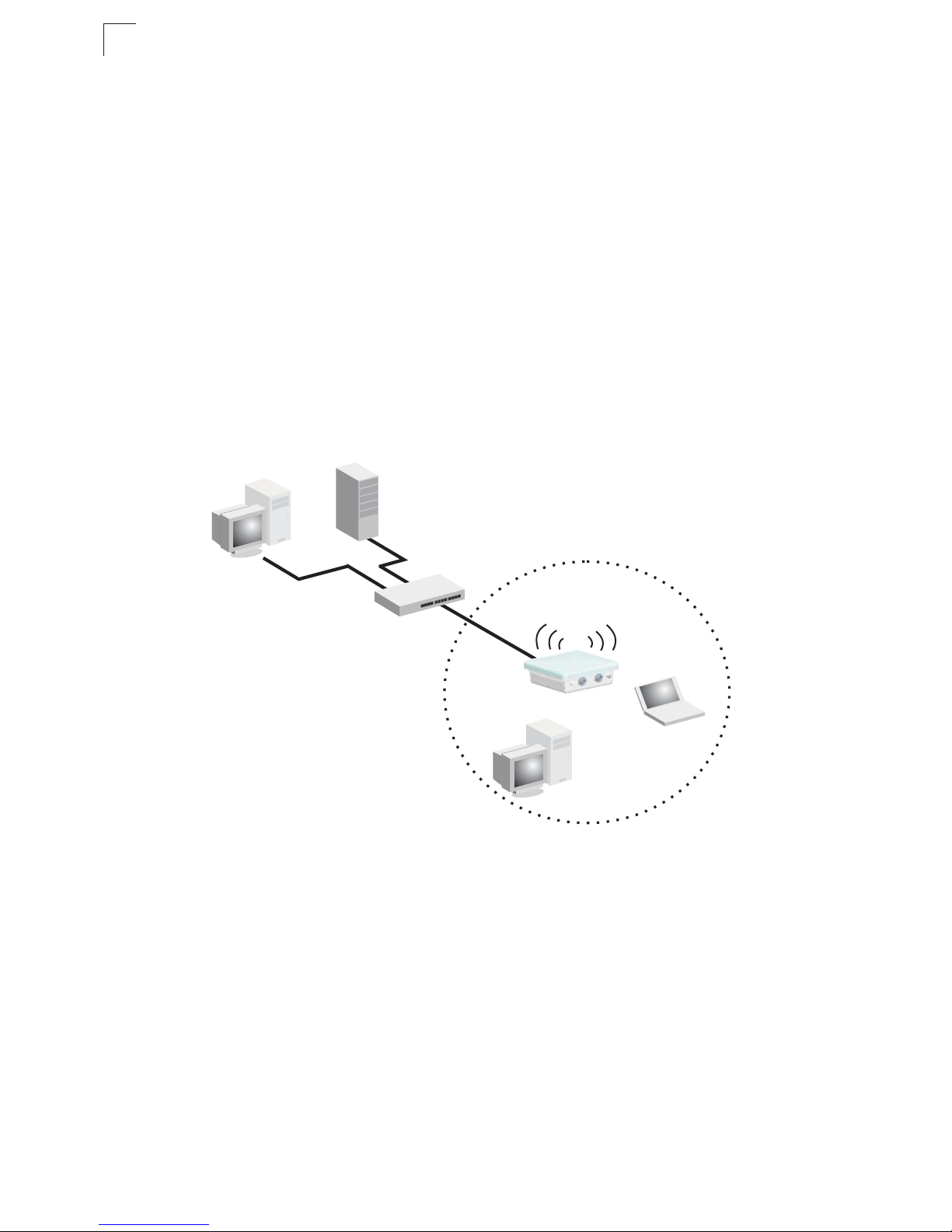
Infrastructure Wireless LAN
The access point fu nction of the wireless brid ge provides access to a wir ed L A N for
802.11a/b/g wireless workstations. An integrated wired/wireless LAN is called an
Infrastructure conf ig ur at ion. A Bas ic Ser vice Set (BSS) consists of a group of
wireless PC users a nd an access point that is di re ct ly connected to the wired LAN.
Each wireless PC in a B SS can connect to any comput e r in its wir eless group or
access other computers or networ k re sources in the wired LAN in frastructure
through the acces s point.
The infrastructure configuration not only extends the accessibility of wireless PCs to
the wired LAN, but als o in cr eases the effective wireless transmission range for
wireless PCs by passi ng t hei r signals through one or mor e access points.
A wireless infrastr uct ur e can be used for acce ss t o a central database, or for
connection between mobile worke rs , as shown in the following fig ur e.
Wired LAN Extension
to Wireless Clients
Desktop PC
Server
Switch
Access Point
Notebook PC
Desktop PC
2-2
Access Point To pologies
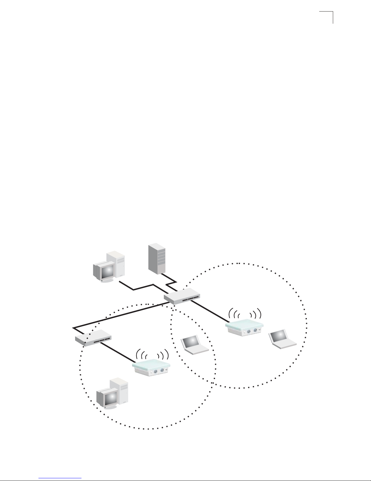
Infrastructure Wireless LAN for Roaming Wireless PCs
The Basic Service Set (BSS) defines the communications domain for each access
point and its associate d wirel ess clients. The BSS ID is a 48-bit binary number
based on the acce ss point’s wireless MAC address, and is set auto m at i cal ly and
transparently as clients as sociate with the access point . The BSS ID is used in
frames sent between the access point and its clients to identify traffic in the service
area.
The BSS ID is only set by the access point, never by i ts clients. The clients only
need to set the Service Set Identifier (SSID) that ide nti fies the ser vi ce set pr ovided
by one or more access po in ts. The SSI D can be manually configured by the clients,
can be detected in an access point’s beacon, or can be obtained by querying for the
identity of the nearest access point. For clients that do not need to roam, set the
SSID for the wireless card to that used by the acc ess point to which you want to
connect.
A wireless infrastructure can also support roaming for mobile workers. More than
one access point ca n be configured to create an Ext ended Service Set (ESS). B y
placing the acce ss points so that a continuous coverage area is created, wireless
users within this ESS can roam freely. All wireless network card adapter s and
wireless access points within a specific ESS must be con f igur ed with the same
SSID.
2
Desktop PC
Switch
Access Point
Desktop PC
Server
Notebook PC
<BSS 1>
Seamless Roaming
Between Access Points
Switch
Access Point
Notebook PC
<BSS 2>
<ESS>
2-3

2
Network Configuration
Bridge Link Topologies
The IEEE 802.11 standard defines a WIreless Distribution System (WDS) for bridge
connections bet w ee n BSS areas (access po in ts). The outdo or wir eless bridge uses
WDS to forward traffic on links between units. Up to 5 WDS links can be specified for
a SMC2890W-AG unit, w hich acts as the “Master” in the wire less bridge network.
Other SMC2891 W-AG units su pport only one WDS link , whi c h m ust be to the
networ k’s master unit.
The unit supports WDS br id ge li nks on either the 5 GHz (802. 11a) or 2.4 GHz
(802.11b/g) bands and can be used with various external antennas to offer flexible
deployment opti ons.
Note: The external antennas offer longer range options using the 5 GHz radio, which
makes this interface more suitable for bridge links. The 2.4GHz radio has various
types of antenna options, but the 8dBi omnidirectional antenna is better suited for
local access point services.
When using WDS on a radio band, only w irel ess bridge units can assoc ia te to each
other. Wireless clients can only associate with the wireless bridge using a radio band
set to access point mode.
Point-to-Point Configuration
Two SMC28 91W-AG bridges can form a wir eless poi nt-to- point li nk using th eir
integrated 5 GHz (802. 11a) antennas. A point-t o- point configuration can pr ovide a
limited data rate (6 Mbps) link ov er a lon g ra nge (up to 15.4 km), or a high da ta rate
(108 Mbps) over a shor t ran ge ( 1. 3 km ) .
SMC2891W-AG SMC2891W-AG
LANLAN
2-4
 Loading...