

SMC Networks D-MP Series, D-MP 050 Series, D-MP 025 Series, D-MP 200 Series, D-MP 100 Series Instruction Manual
D-MP-SMX03EN
SIO mode
Available
Min
imum cycle time
1 ms
Process data length
Input
: 2 byte
s,
Output: 0 bytes
Device ID
125 hex 126 hex
127 hex
128 hex
Vendor ID
83 hex
output
output
active
PNP: ON, NPN: OFF
PNP: OFF, NPN: ON
LED flashing.
range
measurement range
ORIGINAL INSTRUCTIONS
Directives
range
±1 mm
±1 mm
±1 mm
±1 mm
(with power supply polarity protection)
Current consumption
48 mA
or less
(when no load is applied)
Repeatability
0.1 mm (@25
C)
current
drop
PNP: 0.1 mA or less
protection
current
resistance
voltage
Lead wire
Standards
CE mark
ed (EMC
and RoHS
D
irective)
, UL
Impact resistance
300 m/s
Insulation resistance
50 MΩ or more with 500 VDC Ohmmeter
Enclosure rating
IEC60529 IP67
Indicator light
Indicator light
Refer to Declaration of
Conformity for relevant
Instruction Manual
Actuator Position Sensor
D-MP# series
The intended use of the actuator position sensor is to monitor the position
of the actuator while connected to the IO-Link communication protocol.
1 Safety Instructions
These safety instructions are intended to prevent hazardous situations
and/or equipment damage. These instructions indicate the level of
potential hazard with the labels of “Caution,” “Warning” or “Danger.”
They are all important notes for safety and must be followed in addition
to International Standards (ISO/IEC)
*1)
ISO 4414: Pneumatic fluid power - General rules relating to systems.
ISO 4413: Hydraulic fluid power - General rules relating to systems.
IEC 60204-1: Safety of machinery - Electrical equipment of machines.
(Part 1: General requirements)
ISO 10218-1: Manipulating industrial robots -Safety. etc.
• Refer to product catalogue, Operation Manual and Handling
Precautions for SMC Products for additional information.
• Keep this manual in a safe place for future reference.
• This product is class A equipment intended for use in an industrial
environment. There may be potential difficulties in ensuring
electromagnetic compatibility in other environments due to conducted
or radiated disturbances.
Caution
Warning
Danger
• Always ensure compliance with relevant safety laws and
standards.
• All work must be carried out in a safe manner by a qualified person in
compliance with applicable national regulations.
• Do not disassemble, modify (including changing the printed
circuit board) or repair.
An injury or failure can result.
• Do not operate the product outside of the specifications.
Fire, malfunction or damage to the product can result.
• Do not operate in an atmosphere containing flammable, explosive
or corrosive gas.
Fire or an explosion can result.
• Do not use the product for flammable or harmful fluids.
Fire, explosion, damage or corrosion can result.
• If using the product in an interlocking circuit:
Provide a double interlocking system, for example a mechanical
system.
• Check the product for correct operation.
Otherwise malfunction can result, causing an accident.
• Do not use the product in a place where static electricity is a
problem.
Product failure or system malfunction may result.
Otherwise electric shock, malfunction or product damage can result.
• Refer to the operation manual on the SMC website
(URL: https://www.smcworld.com) for more safety instructions.
*1)
, and other safety regulations.
Caution indicates a hazard with a low level of risk which, if
not avoided, could result in minor or moderate injury.
Warning indicates a hazard with a medium level of risk
which, if not avoided, could result in death or serious injury.
Danger indicates a hazard with a high level of risk which, if
not avoided, will result in death or serious injury.
Warning
2 Specifications
2.1 General specifications
Model
Length determination
Power supply voltage
Resolution 0.05 mm
Linearity ±0.3 mm (@25 oC)
Switch
output
Analogue
current
output
Analogue
voltage
output
Withstand voltage 1000 VAC 1 minute
Ambient temperature -10 to 60 oC
2.2 IO-Link specifications
Model
IO-Link type Device
IO-Link version V1.1
Communication
speed
Max. load
Internal
voltage
Leakage
current
Short
circuit
Output
Max. load
Output
Min. load
resistance
D-MP
025∗
25 mm
15 to 30 VDC, ripple (p-p) 10% or below
NPN: 0.5 mA or less at load resistance 3 kΩ,
1.5 mA or less at load resistance 750 Ω
D-MP
025∗
D-MP
050∗
50 mm
NPN or PNP 1 output (push-pull)
2 V or less
4 to 20 mA
PUR 4 core φ2.6 0.08 mm2
D-MP
050∗
COM3 (230.4 kbps)
100 mm
40 mA
Yes
500 Ω
0 to 10 V
2 kΩ
D-MP
100∗
200 mm
o
2
D-MP
100∗
D-MP
200∗
D-MP
200∗
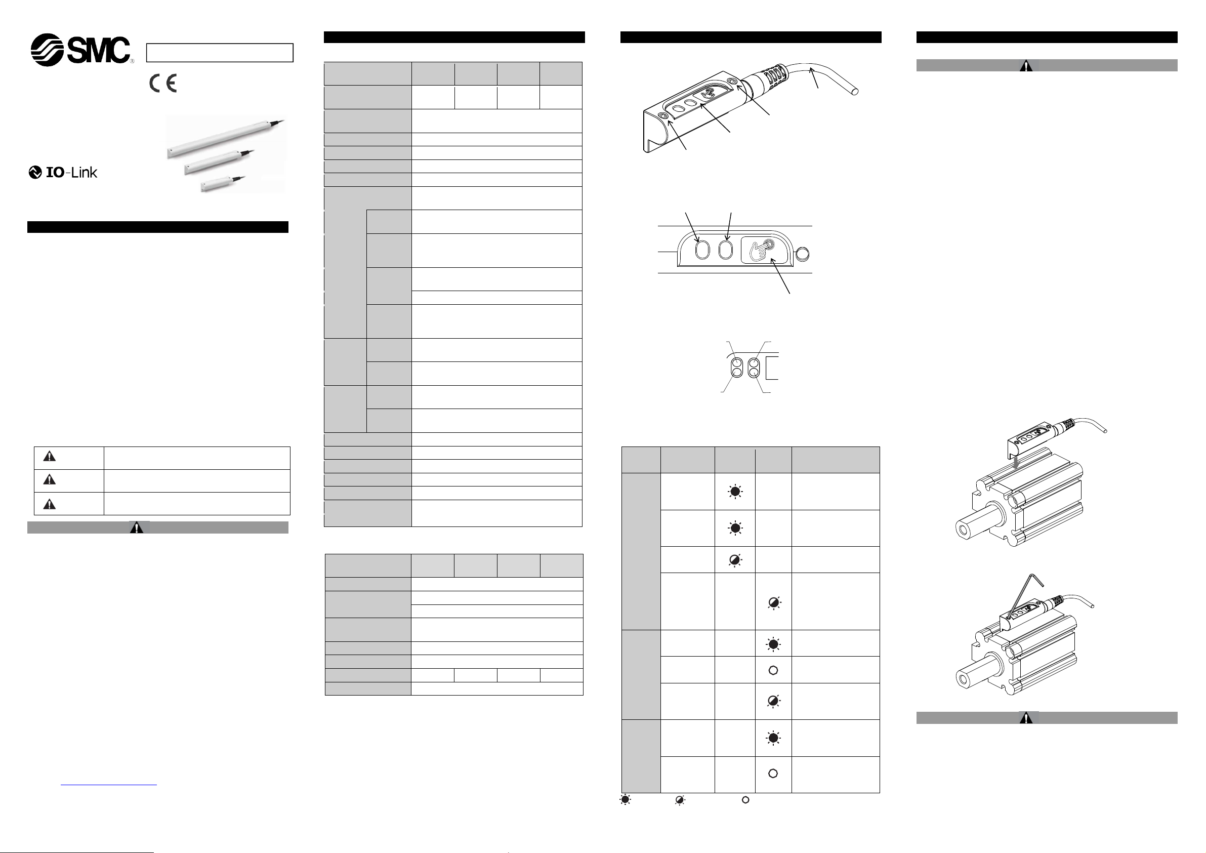
3 Names of Individual parts
3.1 D-MP#
Operation display
3.2 Operation Display
Operation Light Colours
Mounting screw
Green
Category Mode
Analogue
Current
Analogue
Voltage
System
status
Switch
output
Magnetic
field
B = Blue, O = Orange, G = Green
IO-Link
Error
High
Low
Over current
error
In measuring
range
Outside of
measuring
= LED ON, = LED flashing, = LED OFF
Indicator
light 2
B
G
G
Indicator
O Sensor not ready for
B Switch output High
B Switch output Low
B Overload of the switch
O Magnetic field
O Magnetic field is not
Lead wire
Mounting screw
Teach pad
Blue Blue
Orange
light 1
Analogue current
output active
Analogue voltage
output active
IO-Link connection
operation /
Detectable magnetic
field is decrease.
LED flashing at 4 Hz
output (over current)
registered in
measuring range
registered in
Description
4 Installation
4.1 Installation
Warning
• Do not install the product unless the safety instructions have been read
and understood.
• Use the product within the specified operating pressure and
temperature range.
• When mounting an actuator position sensor, use a mounting bracket
appropriate for the cylinder/actuator.
• The mounting method differs according to the type of actuator and the
inner diameter of the tube.
• When mounting a sensor for the first time, check that the
cylinder/actuator has a built-in magnet and use an appropriate bracket
for the cylinder/actuator. There are also cases when a bracket is not
needed.
• Use the correct tightening torque
When tightening mounting screws, use a suitable hexagon wrench
(size 1.5). Recommended torque should be 0.2 to 0.4 Nm.
Over-tightening can damage the cylinder/actuator and sensor.
Loose screws can cause misalignment or a reduction in accuracy
during operation. Tightening below the specified tightening torque will
allow the position sensor to move out of position.
• Do not carry an actuator by the position sensor lead wire.
• This may cause a broken lead wires or damage to the auto switch
internal elements.
• Use only the screws installed in the position sensor body for mounting
the position sensor.
If other screws are used, the position sensor may be damaged.
• Check and adjust the actual product operation during installation.
The auto switch may not operate in the correct actuator mounting
position due to the installation environment. Also check and adjust the
auto switch operation when used in intermediate stroke positions,
according to the operating environment.
• Press the switch down into the cylinder/actuator switch mounting
groove as shown.
• Tighten the mounting screws evenly.
4.2 Environment
Warning
• Do not use in an environment where corrosive gases, condensation,
chemicals, salt water or steam are present.
• Do not use in an explosive atmosphere.
• Do not expose to direct sunlight. Use a suitable protective cover.
• Do not install in a location subject to vibration or impact in excess of
the product’s specifications.
• Do not mount in a location exposed to radiant heat that would result in
temperatures in excess of the product’s specifications.
• Do not use in a location where magnetic fields are generated.
Page 1 of 3
D-MP-SMX03EN
Main circuit
Brown (1)
L+
White (2)
Blue (3)
L-
Click and hold
the teach pad
the pad
the pad
the pad
the pad
selected
Hold
0.1 to 0.5
[s] 0.1 to 0.5
[s]
OFF
4 Installation (continued)
4.3 Wiring
Caution
• Do not perform wiring while the power is on.
• Confirm proper insulation of wiring.
Check that there is no faulty wiring insulation (short circuits, faulty
ground connections, improper insulation between terminals, etc.), as
this may damage the auto switch due to over current.
• Do not route the auto switch wiring in the same place as power cables
or high voltage cables.
Otherwise auto switch malfunction may result due to noise and inrush
current.
• Avoid repeatedly bending or stretching the lead wire.
Broken lead wires will result if bending stresses or tensile forces are
applied to the lead wires.
Stress and tensile forces applied to the connection between the lead
wire and the product increases the possibility of disconnection.
Secure the lead wire to reduce any movement in the area where the
lead wire connects with the position sensor.
• Do not allow short-circuit of loads.
There is a risk of damage of position sensor.
• Keep wiring as short as possible to prevent interference from
electromagnetic noise and surge voltage. Do not use a cable longer
than 20 m.
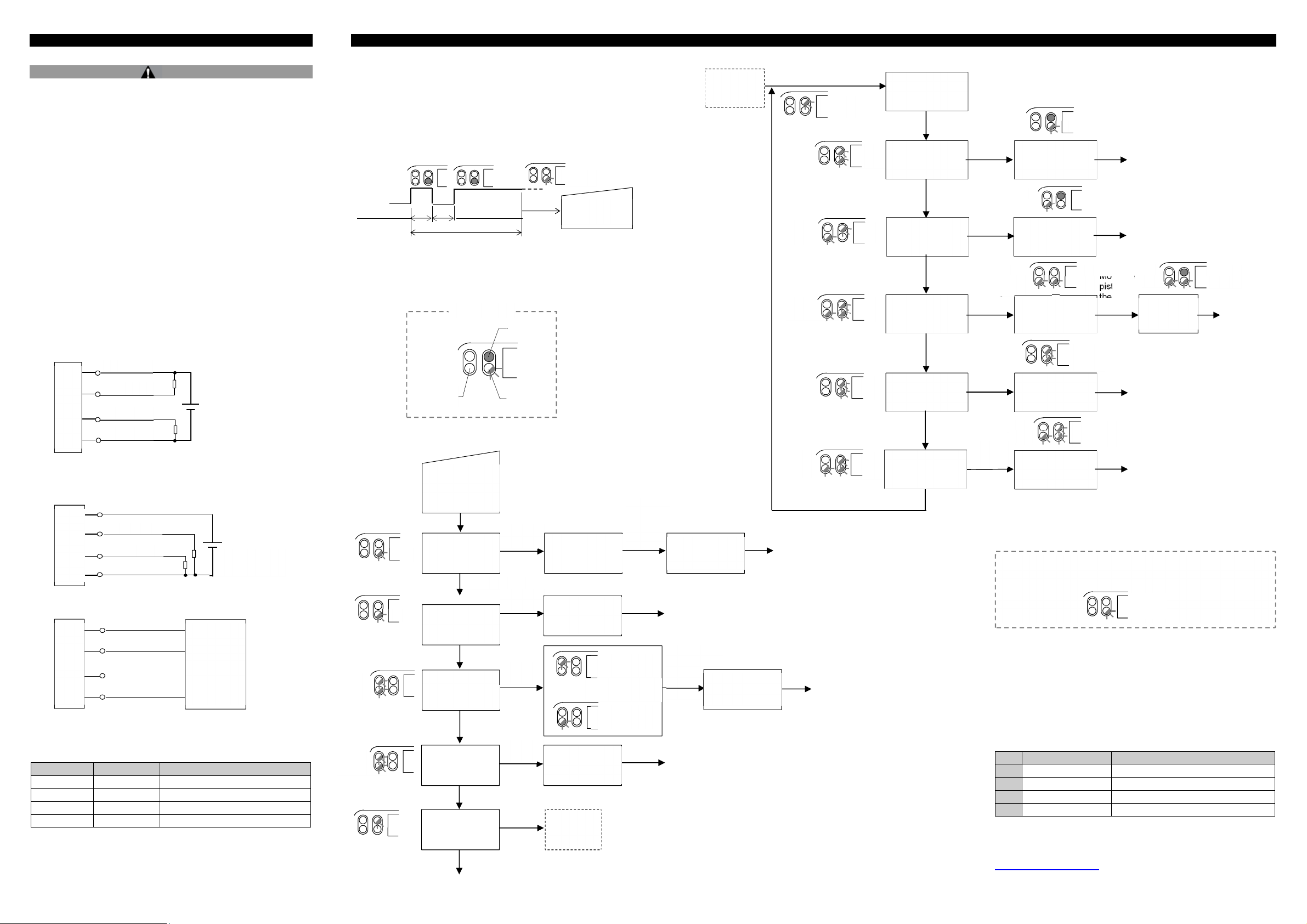
4.4 Wiring Diagram
SIO mode - NPN output
Brown (1)
Black (4)
White (2)
Main circuit
SIO mode - PNP output
Main circuit
IO-Link mode
• Analogue output (white) is disabled when IO-Link mode is selected.
4.5 Connector pin layout
Pin number Wire colour Description
1 Brown Power supply DC (+)
2 White Analogue current / voltage output
3 Blue Power supply DC (-)
4 Black IO-Link / Switch output (C/Q)
Blue (3)
Brown (1)
Black (4)
White (2)
Blue (3)
Black (4) C/Q
Power supply
15 to 30 VDC
Power supply
15 to 30 VDC
IO-Link
master
5 Setting
5.1 Initial settings
Switch output: Low (NPN = ON, PNP = OFF),
Analogue output: Current output, Range: Full range
• Teach pad setting procedure
NOTE: For teaching the measurement range, make sure that the piston
position is at the start point of the range.
Click the teach pad, and then click and hold down the teach pad.
• Teach Level 1 starts when the indicator LED flashes slowly.
NOTE: If the indicator LED does not flash and setting is not available,
wait for 3 seconds and double-click the teach pad again.
5.2 Teach Level 1
2 [Hz]
2 [Hz]
4 [Hz]
4 [Hz]
2 [Hz]
4 [Hz]
2 [Hz]
2 [s]
Display
LED
Click, then click
and hold down
the teach pad
Teaching of the
measurement
range
2 s or more
Measurement
range reset
5 s or more
Change the
analogue output
mode
8 s or more
Reverse
analogue output
11 s or more
Switch output
mode
15 s or more
Complete
LED ON
LED
flashing
Release
the pad
Release
Release
Release
Release
2 [Hz]
Teach Level 1
The start point
is selected
Measurement
range reset
completed
Analogue output
reverse
completed
Teach
Level 2
Current output
mode
Click the teach pad
to change
Voltage output
mode
Move the
piston,
then click
the pad
5.3 Teach Level 2
The end point
is selected
Complete
for 2 s or
longer
Complete
Teach
Level 2
The analogue
output mode is
2 [Hz]
2 [Hz]
4 [Hz]
Complete
2 [Hz]
Complete
2 [Hz]
2 [Hz]
2 [Hz]
2 [Hz]
2 [Hz]
2 [Hz]
4 [Hz]
2 [Hz]
4 [Hz]
Click and hold
the teach pad
Single switch point
mode
3 s or more
Auto switch
mode
6 s or more
Window mode
9 s or more
Switch point
reset
12 s or more
Reverse switch
output
15 s or more
Release
the pad
Release
the pad
Release
the pad
Release
the pad
Release
the pad
Single switch point
1 [s]
2 [Hz]
1 [s]
5.4 Setting completed
When a magnet (subject to be detected) is present outside of the
measurement range, the indicator LED flashes 4 times and setting
is complete.
5.5 IO-Link parameter settings
• IODD file
IODD (I/O Device Description) is a definition file which provides all
properties and parameters required for establishing functions and
communication of the device.
IODD includes the main IODD file and a set of image files such as vendor
logo, device picture and device icon.
The IODD file is shown below.
Product No.
1 D-MP025A/B/C SMC-D-MP025-yyyymmdd-IODD1.1
2 D-MP050A/B/C SMC-D-MP050-yyyymmdd-IODD1.1
3 D-MP100A/B/C SMC-D-MP100-yyyymmdd-IODD1.1
4 D-MP200A/B/C SMC-D-MP200-yyyymmdd-IODD1.1
∗: "yyyymmdd" indicates the file preparation date. yyyy year, mm month
and dd day.
The IODD file can be downloaded from the SMC website (URL:
https://www.smcworld.com)
1 [s]
setting
Switch point
setting
2 [Hz]
Start point
setting
4 [Hz]
1 [s]
Reset
completed
Reverse
completed
1 [s]
1 [s]
Move the
piston,
then click
the pad
4 [Hz]
Complete
Complete
1 [s]
End point
setting
Complete
Complete
1 [s]
IODD file ∗
Complete
Page 2 of 3
 Loading...