

SMC Networks D-M9N, D-M9P, D-M9B Installation And Maintenance Manual
D-*S-TFQ39
Page 1 of 3
Installation and Maintenance Manual
[Auto Switch (Solid State)]
Series D-M9N, D-M9P, D-M9B
(Complies with the basic safety principles in accordance with
ISO 13849)
The intended use of this product is to detect a position of a magnet in a
pneumatic cylinder.
Validated D-M9 components according to ISO 13849:
For the part numbers of validated D-M9 products refer to Doc. No. D-*SSMQ0018.
Safety Instructions
This manual contains essential information for the protection of users and
others from possible injury and/or equipment damage.
• Read this manual before using the product, to ensure correct handling,
and read the manuals of related apparatus before use.
• Keep this manual in a safe place for future reference.
• These instructions indicate the level of potential hazard by label of
“Caution”, “Warning” or “Danger”, followed by important safety
information which must be carefully followed.
• To ensure safety of personnel and equipment the safety instructions in
this manual and the product catalogue must be observed, along with
other relevant safety practices.
• Always ensure compliance with relevant safety law s and standards.
Caution
Indicates a hazard with a low level of risk, which if not
avoided, could result in minor or moderate injury.
Warning
Indicates a hazard with a medium level of risk, which
if not avoided, could result in death or serious injury.
Danger
Indicates a hazard with a high level of risk, which if
not avoided, will result in death or serious injury.
This product is class A, group 1 equipment that is only intended for use in
an industrial environment as described by EN55011.
Common Auto Switch Precautions
Design and Selection
Warning
(1) Check the specifications.
If the auto switch is used with an excessive load or used outside of the
specifications, it may cause damage or malfunction.
The product cannot be guaranteed if is used outside of the specification range.
(2) Caution for use in an interlock system.
When an auto switch is used in an interlock system which requires high reliability,
provide a double interlock system, for example a mechanical protection system, for
extra safety, or by also using another switch (sensor) together with the auto switch.
Check the product regularly in order to confirm normal operation.
(3) Do not disassemble, modify (including changing the printed circuit
board) or repair.
An injury or failure can result.
Caution
(1) Pay attention to the length of time the auto switch will operate at an
intermediate stroke position.
When an auto switch is placed at an intermediate stroke position, and a load is
driven during the time when the piston passes, the auto switch will operate, but if
the piston speed is too great, the operating time will be shortened, and the load
may not operate correctly.
The maximum piston speed is:
V [mm/s] =
Auto switch operating range [mm]
×1000
Load operating time [ms]
(2) Take precautions when multiple actuators are used close together.
When using two or more actuators with auto switches in close proximity to each
other, maintain a minimum separation distance of at least 40 mm. (If the separation
distance is specified for the actuator series, then use that value).
The auto switches may malfunction due to magnetic field interference.
Use of a magnetic screen plate (MU-S025) or commercially available magnetic
screening tape can reduce the interference of magnetic fields.
(3) Provide sufficient space for maintenance.
When designing an application, allow sufficient clearance for maintenance and
inspection.
(4) Never mount the actuator with auto switch in a location that will be used
as a footrest.
The product may be damaged if excessive force is applied by stepping or climbing
onto it.
(5) Design the circuit to prevent reverse current during open circuit
conditions or when the product is forced to operate for functional checks.
Reverse current can cause product damage or malfunction.
(6) Precautions for mounting an auto switch
When n number of auto switches is specified for mounting, this indicates the
maximum number of auto switches based on the physical dimensions of the
actuator.
The detection distance varies depending on the auto switch mounting structure
and the auto switch body dimensions. For this reason, the switch may not always
be mounted at the required detection distance or at the required position.
(7) Limitations of the detection position.
There will be mounting positions or surfaces where the auto switch cannot be
mounted due to physical interference (e.g. rear side of the foot bracket), depending
on the mounting conditions of the actuator.
Select an auto switch after confirming that the switch mounting position does not
interfere with the mounting bracket (e.g. trunnion, reinforcement ring).
Mounting and Adjustment
Caution
(1) Do not drop or apply impact.
The auto switch may be damaged or malfunction if it is dropped, bumped or applied
with excessive impact (1000 m/s2 or more).
(2) Observe the required tightening torque for mounting an auto switch.
If an auto switch is tightened beyond the specified tightening torque, the auto
switch, mounting screws, or mounting bracket may be damaged.
Tightening below the specified tightening torque will allow the auto switch to move
out of position.
(3) Do not carry an actuator by the auto switch lead wire.
This may cause a broken lead wire or damage to the auto switch internal elements.
(4) Use only the screws installed in the auto switch body for mounting the
auto switch.
If other screws are used, the auto switch may be damaged.
(5) Mount the auto switch at the centre of its operating range.
Auto switches should be mounted so that the most sensitive position is at the
centre of the operating range.
Mounting the auto switch close to the edge of its operating range (close to the
border of ON/OFF operation) may cause unstable operation.
(The auto switch mounting positions shown in the actuator catalogue indicate the
optimum position at the end of stroke).
Some actuator and cylinder series have their own setting methods. In such cases,
follow the instructions given.
(6) Check and adjust the actual auto switch operation during installation.
The auto switch may not operate in the correct actuator mounting position due to
the installation environment.
Also check and adjust the auto switch operation when used in intermediate stroke
positions, according to the operating environment.
Wiring
Caution
(1) Check the insulation of the wiring.
Check that there is no faulty wiring insulation (short circuits, faulty ground
connections, improper insulation between terminals, etc.), as this may damage the
auto switch due to over current.
(2) Do not route the auto switch wiring in the same place as power cables
or high voltage cables.
Otherwise auto switch malfunction may result due to noise and inrush current.
(3) Avoid repeatedly bending or stretching the lead wire.
Broken lead wires will result if bending stresses or tensile forces are applied to the
lead wires.
Stress and tensile forces applied to the connection between the lead wire and auto
switch increases the possibility of disconnection.
Secure the lead wire to reduce any movement in the area where the lead wire
connects with the auto switch.
The standard of bending radius becomes R20 to 40 mm.
(4) Be sure to confirm the load condition (e.g. connection and current
value) before power is supplied.
Operating Environment
Warning
(1) Do not use the auto switch in the presence of explosive gases.
Auto switches are not designed with an explosion proof construction. Fire or an
explosion may result.
Contact SMC for information regarding ATEX compliant products.
Caution
(1) Do not use in a location where magnetic fields are generated.
Auto switches will malfunction or the magnets inside actuators will become
demagnetized.
(2) Do not use in an environment where the auto switch will be continually
exposed to water.
Although auto switches satisfy the IEC standard IP67 construction, do not use in
applications continually exposed to water splashes or spray. Otherwise, insulation
failure or malfunction may result.
(3) Do not use in an environment where oil or chemical splashes can
occur.
If auto switches are used in an environment with coolants, cleaning solvents, oils or
chemicals for even a short time, they may be adversely affected by insulation
failure, malfunction due to swelling of the potting resin, or hardening of the lead
wires.
(4) Do not use in an environment where there are cyclic temperature
changes.
Temperature cycles other than normal temperature changes can adversely affect
the auto switch internally.
(5) Avoid accumulation of iron debris or close contact with magnetic
substances.
When a large amount of iron waste such as machining chips or spatter has
accumulated, or a magnetic substance (something attracted by a magnet) is
brought into close proximity with the actuator, it may cause the auto switch to
malfunction due to a weakening of the magnetic force inside the actuator.
(6) Contact SMC for information regarding auto switch water resistance,
elasticity of lead wires, applications in welding sites, etc.
(7) Do not use in direct sunlight.
(8) Do not mount the auto switch in locations where it is exposed to radiant
heat.
(9) The auto switch is CE marked, but not immune to lightning strikes. Take
measures against lightning strikes in the system.
Maintenance
Warning
(1) Removal of equipment, and exhausting the compressed air.
When equipment is to be removed, first confirm that measures are in place to
prevent losing control of the equipment or workpieces from falling, etc. Turn off the
power supply, stop the air supply and exhaust all compressed air from the system.
Before restarting the equipment, confirm that measures are taken to prevent
sudden movement.
(2) Never touch the terminals while the power is on.
Otherwise electric shock, malfunction and damage to the product can result.
Caution
(1) Perform the following maintenance regularly to avoid possible danger
due to unexpected auto switch malfunction.
1) Securely tighten the auto switch mounting screws.
If the screws have become loose and the required mounting position has been
lost, re-adjust the auto switch to the correct mounting position and re-tighten the
screws.
2) The mounting screw is not tamper proof therefore it is foreseeable that misuse
could result in system malfunction.
3) Check that there is no damage to the lead wire.
If damage to the lead wire is found, replace the auto switch, or repair the lead
wire, to avoid faulty insulation.
4) Check the detecting position setting.
Confirm that the auto switch most sensitive position is at the centre of the
operating range (red LED range).
Some actuator and cylinder series have their own setting methods. In such
cases, follow the instructions given.
(2) Do not use solvents such as benzene, thinner, alcohol etc. to clean the
auto switch.
This may damage the surface of the body or erase the markings on the body.
For heavy stains, use a cloth soaked with diluted neutral detergent and fully
squeezed, then wipe up the stains again with a dry cloth.
Solid state Auto switch
Design and Selection
Caution
(1) Wiring should be kept as short as possible.
Do not use a cable longer than 100 m.
For long wire lengths, we recommend a ferrite core should be attached to both
ends of the cable, to reduce noise.
(2) Do not use a load which generates a surge voltage.
When a load which generates a surge voltage is to be directly driven, operate such
as a relay or solenoid, use an auto switch with built-in surge protection.
(3) Pay attention to the internal voltage drop of the switch.
In general, the internal voltage drop will be greater with a 2-wire solid state auto
switch than with a reed type auto switch.
When auto switches are connected in series, the voltage drop will be "n" times
larger when "n" auto switches are connected.
Even though an auto switch may operate normally, the load may not operate.
Note that a 12 VDC relay is not applicable.
(4) Pay attention to the leakage current.
<2-wire type>
With a 2 wire solid state auto switch, current (leakage current) flows to the load to
operate the internal circuit even when the switch is in the OFF state.
Current to operate load (OFF condition) > Leakage current
If the criteria given in the above formula are not met, the auto switch will not reset
correctly (stays ON).
Use a 3 wire type auto switch if this specification cannot be satisfied.
In addition, leakage current flow to the load will be "n" times larger when "n" auto
switches are connected in parallel.
(5) The solid state auto switch output will be unstable for 50 ms after power
is supplied.
During the time after supplying power, the input device (e.g. PLC, relay) may
consider the ON position as OFF output or the OFF position as ON output.
Please set up the application to consider the signals will be invalid within 50 ms
after power is supplied.
Perform a similar setting when using the SMC AHC system (Auto Hand Changing
system) MA series.
Wiring
Caution
(1) Do not short-circuit the load.
The auto switch will be damaged if the load is short-circuited.
(2) Avoid incorrect wiring.
1) If connections are reversed on a 2-wire type auto switch, the switch will not be
damaged if protected by a protection circuit, but the switch will always stay in an
ON state.
However, it is still necessary to avoid reversed connections, since the switch
could be damaged by a load short circuit in this condition.
2) If connections are reversed (power supply wire + and -) on a 3-wire type auto
switch, the switch will be protected by a protection circuit. However, if the blue
wire is connected to the power supply (+) and the black wire is connected to the
power supply (-), the auto switch will be damaged.
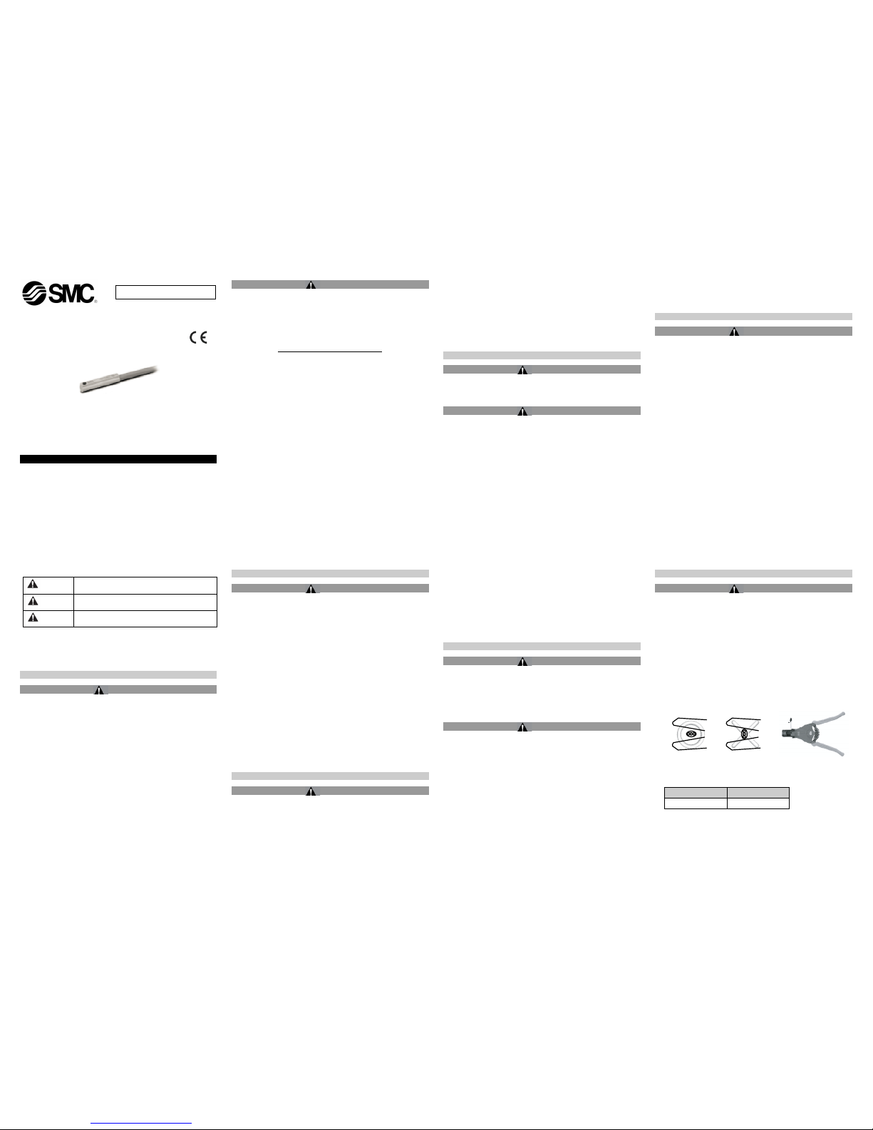
(3) Please note the correct stripping direction when removing the cable
sheath. The insulator may be split or damaged depending on the
direction used.
Recommended tool:
Description
Part number
Wire stripper
D-M9N-SWY
*: For 2-wire type auto switches, a round wire stripper (2.0) can be used.
ORIGINAL INSTRUCTIONS
D-*S-TFQ39
Page 2 of 3
Operating Environment
Caution
(1) Do not use in a location where surges are generated.
When there are units (solenoid lifter, high frequency induction furnace, motor, etc.)
which generate a large amount of surge in the area around the actuator with solid
state auto switches, this may cause damage to the auto switch internal circuit.
Model Indication and How to Order
Specifications
Switch model
No.
D-M9N
D-M9P
D-M9B
Wiring
3 wire
2 wire
Output
NPN
PNP
-
Application
IC circuit / Relay / PLC
24 VDC
Relay / PLC
Power voltage
5/12/24 VDC (4.5 to 28 VDC)
-
Current
consumption
10 mA or less
-
Load voltage
28 VDC or less
-
24 VDC (10
to 28 VDC)
Load current
40 mA or less
2.5 to 40 mA
Internal
voltage drop
0.8 V or less at 10 mA load current (2
V or less at 40 mA)
4 V or less
Current
leakage
100 A or less at 24 VDC
0.8 mA or
less
Operating time
1 ms or less
Indicator light
Operating position: Red LED lights up
Optimum position: Green LED lights up (D-M9W only)
Electrical entry
system
Grommet
Lead wire
Oil-proof heavy-duty vinyl cord 2.7 x 3.2 oval, 0.15
mm2, 2 wire (D-M9B), 3 wire (D-M9N/D-M9P)
Impact
resistance
1000 m/s2
Vibration
resistance
10 to 150 Hz, at the smaller amplitude,
1.5 mm or 20 m/s2 in X,Y,Z directions for 2 hours each
(De-energized)
Insulation
resistance
50 M or more at 500 VDC mega
Withstand
voltage
1000 VAC for 1 minute
(between terminals and housing)
Ambient
temperature
-10oC to 60oC
Protection
structure
IEC60529 standard IP67, JISC0920
Product Elements
D-M9
D-M9V
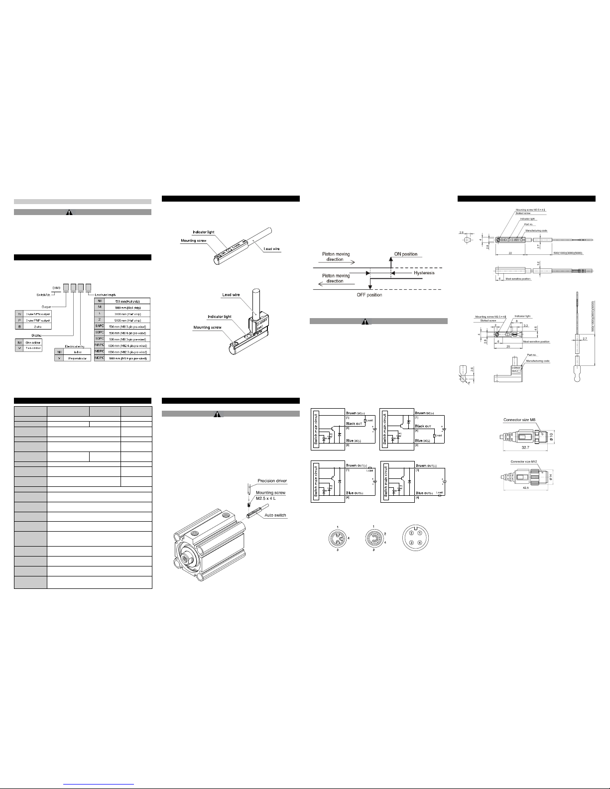
Installation
Warning
• Do not install the product unless the safety instructions have been read
and understood.
Mounting
Each actuator has a specified mounting bracket for mounting the auto
switch.
"How to mount / Mounting bracket" depends on the actuator type and the
tube I.D. Please refer to the actuator catalogue.
When an auto switch is mounted for the first time, ensure that the actuator
is a type including a built in magnet, and select a bracket corresponding to
the actuator.
• Setting the detecting position
1) Set the actuator at the end of stroke.
2) Mount the auto switch in the position where the red LED is ON
(detecting position for the actuator end of stroke).
3) Based on the A and B dimensions in the actuator catalogue, set the
switch.
• Hysteresis
Environment
Warning
• Do not use in an environment where corrosive gases, chemicals, salt
water or steam are present.
• Do not install in a location subject to vibration or impact. Check the
product specifications.
D-M9N D-M9P
D-M9B (Sink input mode) D -M9B (Source input mode)
*1: For the D-M9(V) single colour auto switch the green LED is removed.
The number shown in brackets [ ] indicates the connector pin number.
M8 3-pin connector M8 4-pin connector M12 4-pin connector
Outline Dimensions (mm)
D-M9
D-M9V
External dimensions of Pre-wired connector
D-M9
A
,B PC
D-M9 DPC
M2.5 mounting screw
tightening torque should
be 0.05 to 0.15 Nm
 Loading...