

SMC Networks D3CM1604V Administrator's Manual

EMTA Cable Modem
D3CM1604V
Administrator Manual
FastFind Links
Getting to Know the EMTA
Installing the EMTA
Preconfiguration Guidelines
Configuring the EMTA

SMC Networks
20 Mason
Irvine, CA. 92618
U.S.A.
Copyright © 2013 SMC Networks
All Rights Reserved
Information furnished by SMC Networks, Inc. (SMC) is believed to be accurate and reliable. However,
no responsibility is assumed by SMC for its use, or for any infringements of patents or other rights of
third parties which may result from its use. No license is granted by implication or otherwise under
any patent or patent rights of SMC. SMC reserves the right to change specifications at any time
without notice
No part of this publication may be reproduced or transmitted in any form or by any means, electronic
or mechanical, including photocopying and recording, or stored in a database or retrieval system for
any purpose without the express written permission of SMC.
Microsoft and Windows are registered trademarks of Microsoft Corporation. Apple and Macintosh are
registered trademarks of Apple, Inc. All other brands, product names, trademarks, or service marks
are property of their respective owners.
This product (Models: D3CM1604V) includes software code developed by third parties, including
software code subject to the GNU General Public License (“GPL”) or GNU Lesser General Public
License (LGPL”). As applicable, the terms of the GPL and LGPL, and information on obtaining access
to the GPL code and LGPL used in this product, are available to you at http://gpl.smc.com/. The GPL
code and LGPL code used in this product is distributed WITHOUT ANY WARRANTY and is subject to
the copyrights of one or more authors. For details, see the GPL Code and LGPL Code for this product
and the terms of the GPL and LGPL.

Contents
Preface ...................................................................................................................... v
Key Features .............................................................................................................. vi
Document Organization .............................................................................................. vii
Document Conventions .............................................................................................. vii
Safety and Warnings ............................................................................................ vii
Typographic Conventions .......................................................................................... viii
1 Getting to Know the EMTA................................................................................... 9
Unpacking Package Contents ................................................................................... 10
System Requirements ............................................................................................... 10
Front Panel ................................................................................................................ 11
Rear Panel ................................................................................................................ 13
Using the Reset Button ............................................................................................. 15
2 Installing the EMTA ............................................................................................ 16
Finding a Suitable Location ....................................................................................... 17
Connecting to the LAN .............................................................................................. 18
Connecting the WAN ................................................................................................. 19
Connecting to the Public Telephone Network ........................................................... 19
Powering on the EMTA ............................................................................................. 20
3 Preconfiguration Guidelines .............................................................................. 21
Configuring Your Computer for TCP/IP ..................................................................... 22
Configuring Microsoft Windows 2000 .................................................................. 22
Configuring Microsoft Windows XP ..................................................................... 23
Configuring Microsoft Windows Vista .................................................................. 24
Configuring Microsoft Windows 7 ........................................................................ 27
Configuring an Apple
Disabling Proxy Settings ........................................................................................... 31
Disabling Proxy Settings in Internet Explorer ...................................................... 31
Disabling Proxy Settings in Firefox ...................................................................... 31
Disabling Proxy Settings in Safari ....................................................................... 32
Disabling Firewall and Security Software .................................................................. 32
Confirming the EMTA’s Online Status ....................................................................... 32
Confirming Your Computer’s Link Status .................................................................. 32
®
Macintosh® Computer ..................................................... 30
iii
D3CM1604V EMTA Cable Modem Administrator Manual

Contents
4 Configuring the EMTA ........................................................................................ 33
Accessing the EMTA’s Web Management ................................................................ 34
Understanding the Web Management Interface ........................................................ 35
Web Management Interface Menus .......................................................................... 36
Viewing System Software Settings ................................................................ 37
Viewing Network Connectivity ....................................................................... 38
Configuring Security Settings ........................................................................ 40
Viewing the MTA Initialization Status ............................................................ 41
Viewing DHCP Information ............................................................................ 42
Viewing Quality of Service Information .......................................................... 43
Viewing Provisioning Information .................................................................. 44
Viewing the Event Log ................................................................................... 45
5 Troubleshooting Procedures ............................................................................. 46
Basic Troubleshooting Procedures ........................................................................... 47
Advanced Troubleshooting Procedures .................................................................... 49
Troubleshooting Physical Network Problems ...................................................... 49
Troubleshooting Configuration Problems ............................................................ 50
Determining Your IP Address ........................................................................ 50
Troubleshooting Software-Interaction Problems ................................................. 54
Specific Troubleshooting Procedures ........................................................................ 54
Unable to Log In to EMTA ................................................................................... 55
Local Networked Devices Unable to Access the EMTA ...................................... 55
Unable to Access the Internet ............................................................................. 56
Unable to Access Networked Devices ................................................................. 57
Using the Ping Utility to Troubleshoot ................................................................. 57
Testing the Path from a Computer to the EMTA ........................................... 57
Testing the Path from a Computer to the Internet ......................................... 59
Using Ping on a Macintosh ............................................................................ 59
EMTA Disconnects from the Internet ................................................................... 60
Slow Web Browsing ............................................................................................. 61
Unable to Configure Port Forwarding .................................................................. 61
EMTA is Not Passing DHCP Address to a computer .......................................... 62
Determining a Computer’s MAC Address ............................................................ 62
Microsoft Windows ........................................................................................ 62
Apple Mac
intosh Windows OS X ................................................................... 63
Appendix A - Glossary .......................................................................................... 64
Appendix B - Compliance ..................................................................................... 65
Index ....................................................................................................................... 67
iv
D3CM1604V EMTA Cable Modem Administrator Manual
Preface
The D3CM1604V EMTA Cable Modem is ideal all-in-one wired solution for the home or
business environment. SMC is proud to provide you with a powerful, yet simple
communication device for connecting your local-area network (LAN) to the Internet.
This Administrator manual contains all the information you need to install and configure your
new D3CM1604V EMTA Cable Modem.
v
D3CM1604V EMTA Cable Modem Administrator Manual

Preface
Key Features
The following list summarizes the EMTA’s key features.
Ÿ Integrated, CableLabs-compliant DOCSIS 1.1/ 2.0 /3.0 cable modem.
Ÿ Integrated cable modem port for Internet connection to cable modem service.
Ÿ One 10/100/1000 Mbps Auto-Sensing LAN ports with Auto-MDI/MDIX.
Ÿ Dynamic Host Configuration Protocol (DHCP) for dynamic IP configuration, and Domain
Name System (DNS) for domain name mapping.
Ÿ Two Plain Old Telephone System (POTS) RJ-11 telephone ports to allow Public Switch
Telephone Network (PSTN) analog phone connections.
Ÿ Advanced SPI firewall EMTA for enhanced network security from attacks over the
Internet:
– Firewall protection with Stateful Packet Inspection
– Client privileges
– Hacker prevention
– Protection from denial of service (DoS) attacks
– Network Address Translation (NAT)
Ÿ Effortless plug-and-play installation.
Ÿ Intuitive graphical user interface (GUI) configuration, regardless of operating system.
Ÿ Comprehensive front panel LEDs for network status and troubleshooting.
Ÿ Compatible with all popular Internet applications.
vi
D3CM1604V EMTA Cable Modem Administrator Manual
Preface
Document Organization
This document consists of five chapters and two appendixes.
Ÿ Chapter 1 – describes the contents in the EMTA package, system requirements, and an
overview of the EMTA’s front, rear, top, and bottom panels.
Ÿ Chapter 2 – describes how to install the EMTA.
Ÿ Chapter 3 – describes how to configure TCP/IP settings on the computer you will use to
configure the EMTA.
Ÿ Chapter 4 – describes how to configure the EMTA.
Ÿ Chapter 5 – provides troubleshooting information you can use in the unlikely event you
encounter a problem with the EMTA.
Ÿ Appendix A - is a glossary that defines the technical terms in this document.
Ÿ Appendix B - contains compliance information.
Document Conventions
This document uses the following conventions to draw your attention to certain information.
Safety and Warnings
This document uses the following symbols to draw your attention to certain information.
Symbol Meaning Description
Note Notes emphasize or supplement important points of the main text.
Tip Tips provide helpful information, guidelines, or suggestions for performing tasks more
Warning Warnings indicate that failure to take a spec if i ed action could result in damage to the
Electric Shock Hazard This symbol warns users of electric shock hazard. Failure to take appropriate
effectively.
device.
precautions such as not opening or touching hazardous areas of the equipment could
result in injury or death.
vii
D3CM1604V EMTA Cable Modem Administrator Manual

Preface
Typographic Conventions
This document also uses the following typographic conventions.
Convention Description
Bold Indicates text on a window, other than the window title, including menus, menu options, buttons, fields, and labels.
Italic Indicates a variable, which is a placeholder for actual text provided by the user or system. Angled brackets (< >)
are also used to indicate variables.
screen/code Indicates text that is displayed on screen or entered by the user.
< > angled
brackets
[ ] square
brackets
{ } braces Indicates required or expected values.
| vertical bar Indicates that you have a choice between two or more options or arguments.
Indicates a variable, which is a placeholder for actual text provided by the user or system. Italic font is also used to
indicate variables.
Indicates optional values.
viii
D3CM1604V EMTA Cable Modem Administrator Manual

1 Getting to Know the EMTA
Before you install your D3CM1604V EMTA Cable Modem, check the package contents and
become familiar with the EMTA’s front and back panels.
The topics covered in this chapter are:
Ÿ Unpacking Package Contents (page 10)
Ÿ System Requirements (page 10)
Ÿ Front Panel (page 11)
Ÿ Rear Panel (page 12)
Ÿ Using the Reset Button (page 15)
9
D3CM1604V EMTA Cable Modem Administrator Manual

Getting to Know the EMTA
Unpacking Package Contents
Unpack the items in your D3CM1604V EMTA Cable Modem contents and confirm that no
items are missing or damaged. Your package should include:
Ÿ One D3CM1604V EMTA Cable Modem
Ÿ One Category 5E Ethernet cable
Ÿ One power supply
Ÿ One set of quick-installation instructions
If any items are missing or damaged, please contact your cable service provider. Keep the
carton, including the original packing material, in case you need to store the product or
return it.
System Requirements
To complete your installation, you need the following items:
Ÿ Provisioned Internet access on a cable network that supports cable modem service.
Ÿ A computer with a wired network adapter with TCP/IP installed.
Ÿ A Java-enabled Web browser, such as Microsoft Internet Explorer 5.5 or above.
Ÿ Microsoft
Ÿ An analog telephone and two RJ-11 cables if you want to connect the EMTA to an
®
Windows® 2000 or higher for USB driver support.
analog telephone and PSTN telephone line.
10
D3CM1604V EMTA Cable Modem Administrator Manual
Getting to Know the EMTA
Front Panel
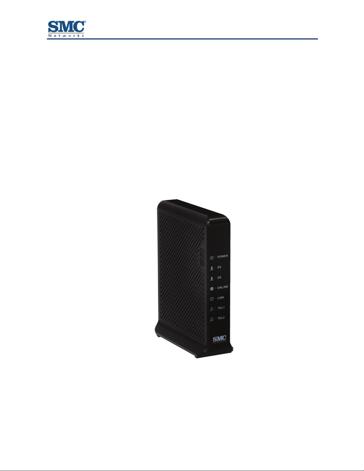
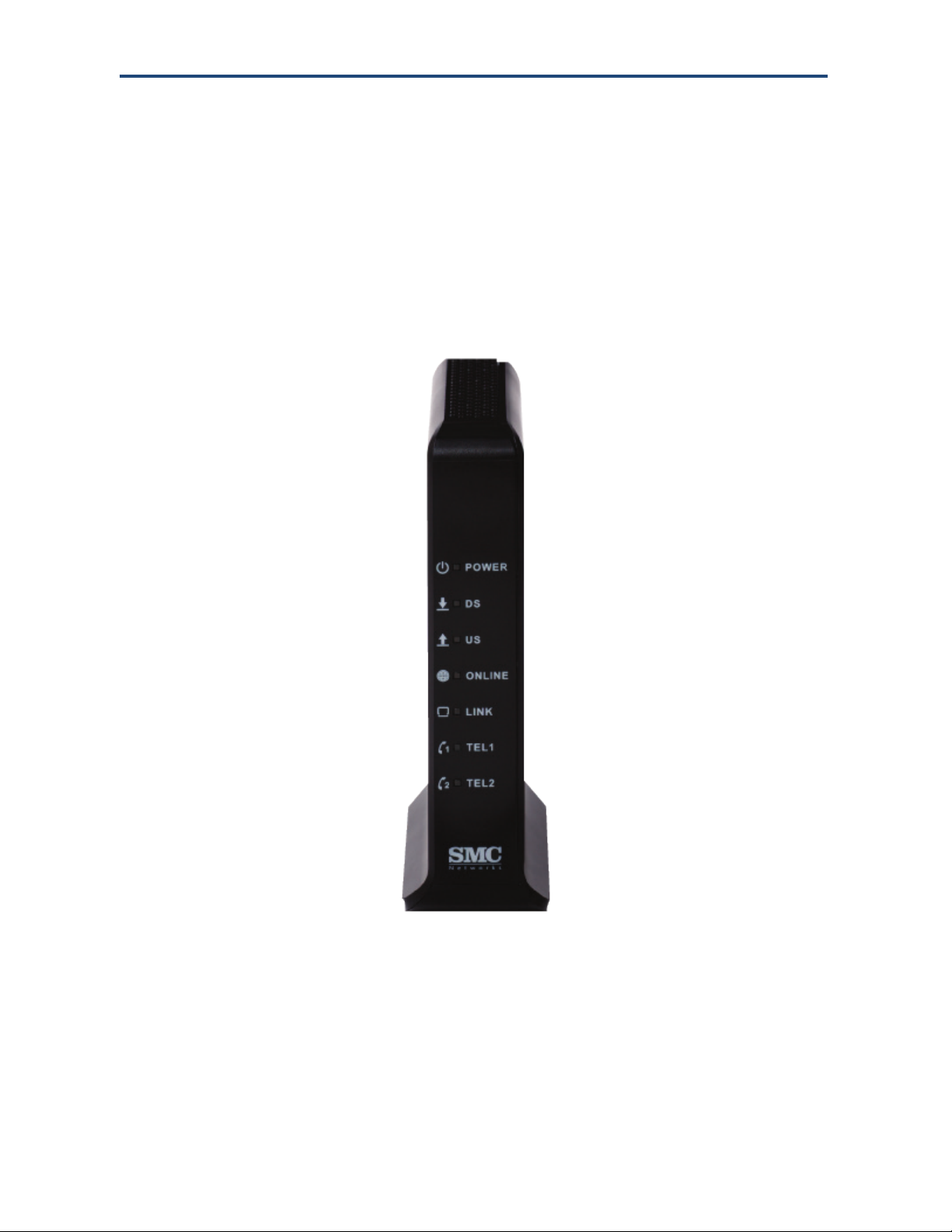
The front panel of your D3CM1604V EMTA Cable Modem contains a set of light-emitting
diode (LED) indicators. These LEDs show the status of the EMTA and simplify
troubleshooting.
Figure
describes the front panel LEDs.
1-1 shows the front panel of the D3CM1604V EMTA Cable Modem. Table 1
Figure 1-1. Front Panel of the D3CM1604V EMTA Cable Modem
11
D3CM1604V EMTA Cable Modem Administrator Manual
Getting to Know the EMTA
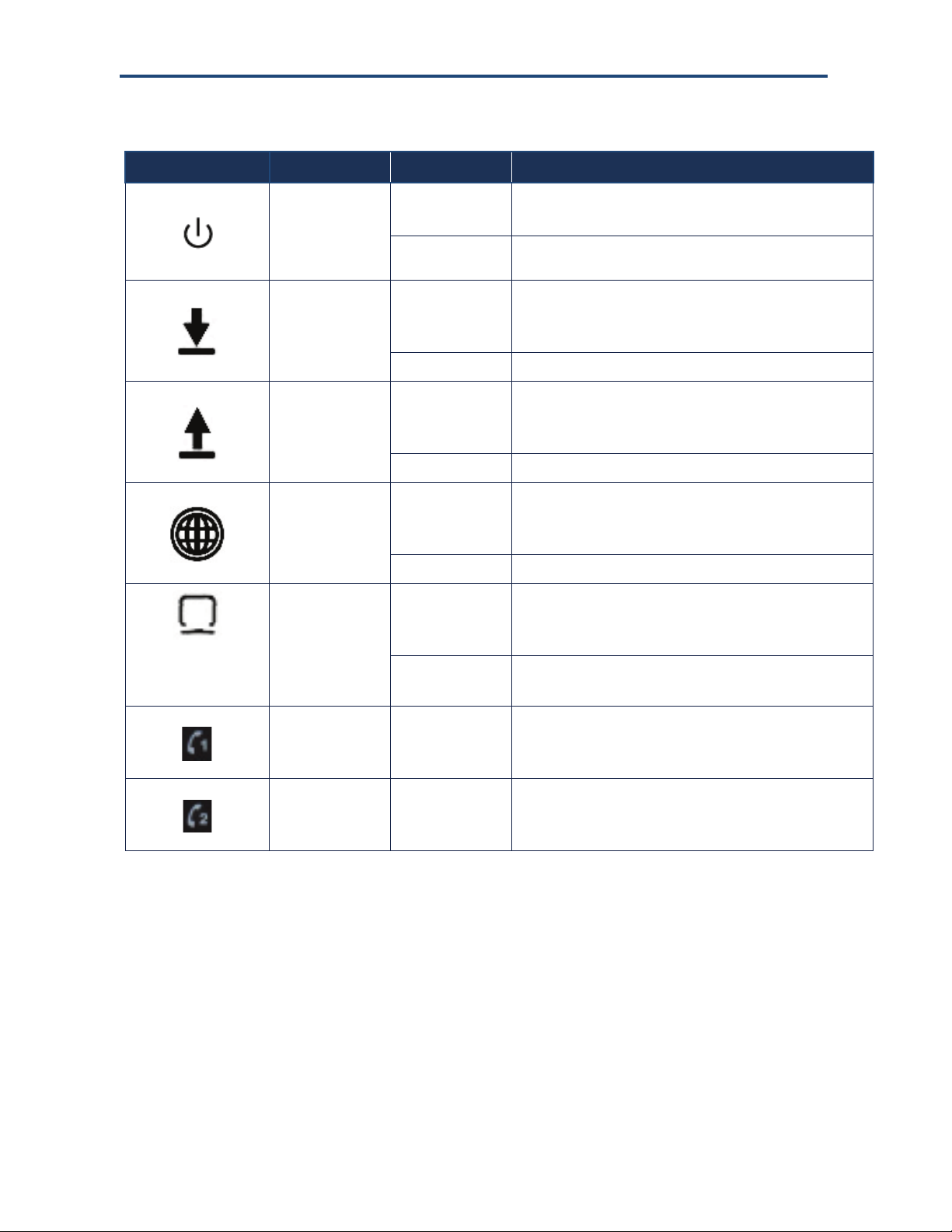
Table 1. Front Panel LEDs
Symbol LED Color Description
POWER OFF = DC power is not supplied to the EMTA.
Green ON = DC power is supplied to the EMTA and power switch is in the
ON position.
DS Blue Blinking = scanning for downstream channel.
ON = locked on DOCSIS 3.0 downstream channel.
OFF = no power.
Green On = locked on DOCSIS 2.0 downstream channel.
US Blue Blinking = ranging is in progress.
ON = ranging is complete, DOCSIS 3.0 bonded upstream.
OFF = no power or not locked on upstream channel.
Green ON = ranging is complete, DOCSIS 2.0 bonded upstream.
ONLINE Blue Blinking = DHCP and registration in progress.
ON = online in DOCSIS 3.0 mode.
OFF = no power or upstream ranging not complete.
Green ON = online in DOCSIS 2.0 mode
LINK Blue Blinking = data activity.
ON = Gigabit Ethernet LAN device connected.
OFF = no LAN devices connected.
Green Blinking = data activity.
ON = 10/100 Ethernet LAN device connected.
Tel1 White Blinking = telephone line 1 is in use.
ON = EMTA’s telephone 1 port is online.
OFF = EMTA’s telephone 1 port is not online.
Tel2 White Blinking = telephone line 2 is in use.
ON = EMTA’s telephone 2 port is online.
OFF = EMTA’s telephone 2 port is not online.
12
D3CM1604V EMTA Cable Modem Administrator Manual
Getting to Know the EMTA
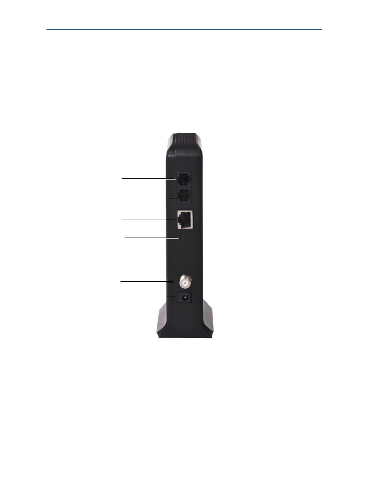
Rear Panel
The rear panel of your D3CM1604V EMTA Cable Modem contains a reset button and the
ports for attaching the supplied power adapter and making additional connections. Figure
1-2 shows the rear panel components and Table 2 describes their meanings.
Figure 1-2. Rear View of the D3CM1604V EMTA Cable Modem
13
D3CM1604V EMTA Cable Modem Administrator Manual
Getting to Know the EMTA
Table 2. D3CM1604V EMTA Cable Modem Rear Panel Components
Label Description
and
TEL1 and TEL2 Connect an analog telephone to one port and an analog (PSTN) telephone line to the other
port.
LAN One 10/100/1000 auto-sensing RJ-45 switch port. Connect a device on your LAN such as a
computer, hub, or switch to these ports.
RST Use this button to reset the power or restore the default factory settings (see “Using the Reset
Button” on page 15).
CABLE Connect your coaxial cable line to this port.
POWER Connect the supplied power cord.
14
D3CM1604V EMTA Cable Modem Administrator Manual

Getting to Know the EMTA
Using the Reset Button
Using the reset button on the rear panel (see Figure 1-2 on page 13), you can perform two
types of reset operations with the EMTA:
Ÿ Software reset – this reset operation power-cycles the EMTA and retains its current
configuration settings.
Ÿ Factory default reset – this operation removes all overrides made to the EMTA’s factory
default configuration and returns the EMTA to its original factory default settings.
The number of seconds you press the reset button determines which reset operation is
performed. To protect against accidental resets, the reset button is recessed on the EMTA
rear panel.
Note: You can also reset the EMTA and retain its current configuration settings using the
RESET method described under “Configuring Security Settings” on page 40.
To use the reset button to perform a software or factory default reset:
1. Leave power plugged into the EMTA.
2. Find the reset button at the top of the back panel, then use a thin object to press and hold
the reset button as follows:
– To perform a software reset, press the reset button for at least 10 seconds.
– To perform a factory default reset, press the reset button for at least 15 seconds.
3. Release the reset button.
15
D3CM1604V EMTA Cable Modem Administrator Manual

2 Installing the EMTA
This chapter describes how to install your D3CM1604V EMTA Cable Modem. The topics
covered in this chapter are:
Ÿ Finding a Suitable Location (page 17)
Ÿ Connecting to the LAN (page 18)
Ÿ Connecting the WAN (page 19)
Ÿ Connecting to the Public Telephone Network (page 19)
Ÿ Powering on the EMTA (page 20)
16
D3CM1604V EMTA Cable Modem Administrator Manual

Installing the EMTA
Finding a Suitable Location
Your D3CM1604V EMTA Cable Modem can be installed in any location with access to the
cable network. All of the cables connect to the rear panel of the EMTA for better organization
and utility. The LED indicators on the front panel are easily visible to provide you with
information about network activity and status.
For optimum performance, the location you choose should:
Ÿ Be close to a working AC power outlet when powering the EMTA using AC power.
Ÿ Allow at least one foot of space around the sides and top of the EMTA to provide
sufficient air flow around the device.
Ÿ Not expose the EMTA to a dusty or wet environment.
Ÿ Be an elevated location such as a high shelf, keeping the number of walls and ceilings
between the EMTA and your other devices to a minimum.
Ÿ Be away from electrical devices that are potential sources of interference, such as ceiling
fans, home security systems, microwaves, or the base for a cordless phone.
Ÿ Be away from any large metal surfaces, such as a solid metal door or aluminum studs.
Large expanses of other materials such as glass, insulated walls, fish tanks, mirrors,
brick, and concrete can also affect your wireless signal.
Ÿ Should allow the EMTA to connect to an AC outlet that is not controlled by a wall switch.
17
D3CM1604V EMTA Cable Modem Administrator Manual
Installing the EMTA
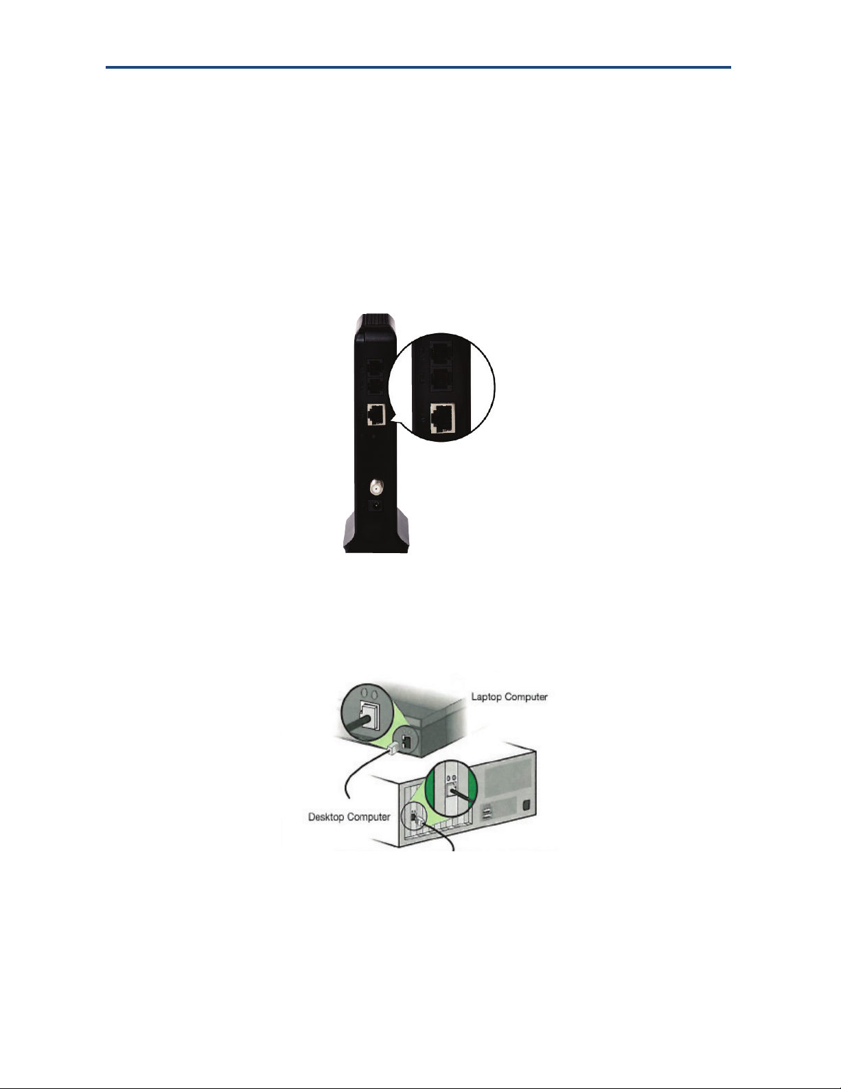
Connecting to the LAN
Using an Ethernet LAN cable, you can connect the EMTA to a desktop computer, notebook,
hub, or switch. The EMTA supports auto-MDI/MDIX, so you can use either a standard
straight-through or crossover Ethernet cable.
1. Connect either end of an Ethernet cable to the LAN port on the rear panel of the EMTA
(see Figure 2-1).
Figure 2-1. Connecting to an Ethernet Port on the EMTA Rear Panel
2. Connect the other end of the cable to your computer’s network-interface card (NIC) or to
another network device (see Figure 2-2).
Figure 2-2. Connecting the EMTA to the a Laptop or Desktop Computer
18
D3CM1604V EMTA Cable Modem Administrator Manual

Installing the EMTA
Connecting the WAN
To connect the EMTA to a Wide Area Network (WAN) interface:
1. Connect a coaxial cable to the port labeled CABLE on the rear panel of the EMTA from a
cable port in your home or office (see Figure 1-2 on page 13). Use only manufactured
coaxial patch cables with F-type connectors at both ends for all connections.
2. Hand-tighten the connectors to secure the connection.
3. If the modem was not installed by your cable provider (ISP) or is replacing another cable
modem, contact your cable operator to register the D3CM1604V . If the modem is not
registered with your cable operator, it cannot connect to the cable network system.
Connecting to the Public Telephone Network
The rear panel of the EMTA has two RJ-11 telephone-style connectors labeled TEL1 and
TEL2. Each of these connectors can provide telephone service to multiple telephones, fax
machines, and analog modems.
The maximum number of telephone devices connected to each RJ-11 port is limited by the
total Ringing Load of the telephone devices that are connected. Many telephone devices are
marked with a Ringer Equivalent Number (REN). Each telephone port on the EMTA can
support up to a 5 REN load. The sum of the REN load on all of the telephone devices
attached to each port must not exceed 5 REN.
Before you use the EMTA’s RJ-11 connectors to power the analog devices in your home or
office, disconnect the telephone lines from any other provider at the demarcation point. If the
incoming phone line is connected to another provider, such as an incumbent telephone
company, it can result in potentially harmful voltage to the analog telephone line.
Note: The customer or the customer's wire contractor is responsible for adhering to all local
codes for wiring.
To set up the ability to place calls using a regular analog telephone line (PSTN), perform the
following procedure.
1. Disconnect the phone lines from any other provider at the demarcation point, if appropriate.
2. Connect the RJ-11 cable on an analog device to the TEL1 connector on the rear panel of
the EMTA.
3. Connect the RJ-11 cable on another analog device to the TEL2 connector on the rear
panel of the EMTA.
19
D3CM1604V EMTA Cable Modem Administrator Manual

Installing the EMTA
Powering on the EMTA
After making your connections, use the following procedure to power on the EMTA:
1. Connect the supplied power cord to the power port on the rear panel of the EMTA (see
Figure 1-2 on page 13).
2. Connect the other end of the power adapter to a working power outlet. The EMTA powers
on automatically, the POWER LED on the front panel goes ON, and the other front panel
LEDs show the EMTA’s status (see Table 1 on page 12).
WARNING: Only use the power supply supplied with the EMTA. Using a different power
supply can damage the EMTA and void the warranty.
20
D3CM1604V EMTA Cable Modem Administrator Manual

3 Preconfiguration Guidelines
After you install your D3CM1604V Wireless EMTA Cable Modem, use the information in this
chapter to configure the TCP/IP settings on the computer that is used to configure the
EMTA. This chapter also covers other preconfiguration guidelines you should review before
configuring the EMTA.
The topics covered in this chapter are:
Ÿ Configuring Your Computer for TCP/IP (page 22)
Ÿ Disabling Proxy Settings (page 31)
Ÿ Disabling Firewall and Security Software (page 32)
Ÿ Confirming the EMTA’s Online Status (page 32)
Ÿ Confirming Your Computer’s Link Status (page 32)
21
D3CM1604V EMTA Cable Modem Administrator Manual
 Loading...