

Page 1

USER GUIDE
SMC7904WBRAS-N
Page 2

Copyright
Information furnished is believed to be accurate and reliable. However, no responsibility is assumed
by our company for its use, nor for any infringements of patents or other rights of third parties which
may result from its use. No license is granted by implication or otherwise under any patent or patent
rights of our company. We reserve the right to change specifications at any time without notice.
Copyright © 2009 by
SMC Networks, Inc.
20 Mason
Irvine, CA 92618
All rights reserved.
Trademarks:
SMC is a registered trademark; and Barricade is a trademark of SMC Networks, Inc. Other product
and company names are trademarks or registered trademarks of their respective holders.
Page 3

Warranty and
Product Registration
To register SMC products and to review the detailed warranty statement, please refer to
the Support Section of the SMC Website at http://www.smc.com
SMC Networks, Inc.
20 Mason
Irvine, CA 92618
Page 4

Compliances
Federal Communication Commission Interference Statement
This equipment has been tested and found to comply with the limits for a Class B digital device, pursuant
to Part 15 of the FCC Rules. These limits are designed to provide reasonable protection against harmful
interference in a residential installation. This equipment generates uses and can radiate radio frequency
and, if not installed and used in accordance with the instructions, may cause harmful interference to radio
communications. However, there is no guarantee that interference will not occur in a particular installation.
If this equipment does cause harmful interference to radio or television reception, which can be determined
by turning the equipment off and on, the user is encouraged to try to correct the interference by one or more
of the following measures:
• Reorient or relocate the receiving antenna.
• Increase the distance between the equipment and receiver.
• Connect the equipment into an outlet on a circuit different from that to which the receiver is connected.
• Consult the dealer or an experienced radio/TV technician for help.
This device complies with Part 15 of the FCC Rules. Operation is subject to the following two conditions:
(1) This device may not cause harmful interference, and (2) this device must accept any interference
received, including interference that may cause undesired operation.
FCC Caution: To assure continued compliance, (example - use only shielded interface cables when
connecting to computer or peripheral devices) any changes or modifications not expressly approved by the
party responsible for compliance could void the user’s authority to operate this equipment.
FCC Radiation Exposure Statement:
This equipment complies with FCC radiation exposure limits set forth for an uncontrolled environment.
This equipment should be installed and operated with a minimum distance of 20cm between the radiator
and your body. This transmitter must not be co-located or operating in conjunction with any other
antenna or transmitter...
Countries of Operation & Conditions of Use in the European Community
SMC contact for these products in Europe is:
SMC Networks Spain, S.L.
Edificio Conata II,
Fructuos Gelabert 6-8 2º,2ª
08970 Sant Joan Despi, Barcolona, Spain
This device complies with the essential requirements of the R&TTE Directive 1999/5/EC. The
following test methods have been applied in order to prove presumption of conformity with the
essential requirements of the R&TTE Directive 1999/5/EC:
- EN 61000-3-2: 2006, Class A
- EN 61000-3-3:2008
Page 5

- EN 61000-4-2:2009
- EN 61000-4-3:2006+A1:2008
- EN 61000-4-4:2004
- EN 61000-4-5:2006
- EN 61000-4-6:2009
- EN 61000-4-11:2004
- EN 60231-2005
- EN 50385:2002
- EN 55022:2006 + A1:2007,Class B
- EN 301 489-1 V1.8.1 (2008-04)
-
EN 301 489-17 V2.1.1 (2009-05)
-
EN 300 328 V1.7.1 (2006-10)
-
EN 60950-1:2006 + A11:2009
This device is a 2.4 GHz wideband transmission system (transceiver), intended for use in all EU
member states and EFTA countries, except in France and Italy where restrictive use applies.
In Italy the end-user should apply for a license at the national spectrum authorities in order to obtain
authorization to use the device for setting up outdoor radio links and/or for supplying public access to
telecommunications and/or network services.
This device may not be used for setting up outdoor radio links in France and in some areas the RF
output power may be limited to 10 mW EIRP in the frequency range of 2454 – 2483.5 MHz. For
detailed information the end-user should contact the national spectrum authority in France.
The official CE certificate of conformity can be downloaded by selecting the relevant model/ part
number from www.smc.com -> support -> download"
Declaration of Conformity in Languages of the European Community
[Czech]
[Danish]
Společnost SMC Networks tímto prohlašuje, že toto rádiové
zařízení LAN je ve shodě se základními požadavky a dalšími
příslušnými ustanoveními směrnice 1999/5/ES. Oficiální ES
prohlášení o shodě je uvedeno v příslušné části k produktu na
webu http://www.smc.com
SMC Networks erklærer herved, at følgende Radio
LAN-enhed overholder de væsentlige krav og andre relevante
Page 6

bestemmelser i direktiv 1999/5/EF. Den officielle
EU-overensstemmelseserklæring er tilgængelig under det
relevante produktafsnit på følgende webadresse:
http://www.smc.com
.
[German]
[Estonian]
[English]
[Spanish]
Hiermit erklärt SMC Networks, dass sich dieses Wireless LAN
Gerät in Übereinstimmung mit den grundlegenden
Anforderungen und den anderen relevanten Vorschriften der
Richtlinie 1999/5/EG befindet. Die offizielle EC-Declaration
of Conformity finden Sie im Internet unter
http://www.smc.com unter der entsprechenden
Produktkategorie.
Käesolevaga kinnitab SMC Networks, et see Radio LAN seade
vastab direktiivi 1995/5/EÜ põhinõuetele ja teistele
asjakohastele sätetele. Ametliku EÜ vastavusdeklaratsiooni
leiate vastavast tootejaotisest aadressil http://www.smc.com
.
Hereby, SMC Networks, declares that this Radio LAN device
is in compliance with the essential requirements and other
relevant provisions of Directive 1999/5/EC. The official
EC-Declaration of Conformity can be found under the
corresponding product section on the web
http://www.smc.com.
Por medio de la presente SMC Networks declara que el Radio
LAN device cumple con los requisitos esenciales y
cualesquiera otras disposiciones aplicables o exigibles de la
Directiva 1999/5/CE. The official EC-Declaration of
Conformity can be found under the corresponding product
section on the web http://www.smc.com
[Greek]
[French]
[Italian]
[Latvian]
Με την παρούσα, η SMC Networks, δηλώνει ότι η συσκευή
ασύρματου τοπικού δικτύου συμμορφώνεται με τις ουσιώδεις
απαιτήσεις και τις λοιπές σχετικές διατάξεις της Οδηγίας
1999/5/EΚ. Η επίσημη δήλωση συμμόρφωσης EΚ παρέχεται
στην αντίστοιχη ενότητα προϊόντων, στην ιστοσελίδα
http://www.smc.com
.
Par la présente SMC Networks déclare que l'appareil Radio
LAN device est conforme aux exigences essentielles et aux
autres dispositions pertinentes de la directive 1999/5/CE. La
déclaration de conformité officielle peut être trouvée sur notre
site internet http://www.smc.com dans la rubrique Produits.
Con la presente SMC Networks dichiara che questo Radio
LAN device è conforme ai requisiti essenziali ed alle altre
disposizioni pertinenti stabilite dalla direttiva 1999/5/CE. La
Dichiarazione di conformità CE ufficiale è disponibile nella
sezione dedicata al rispettivo prodotto sul sito Web
http://www.smc.com
.
Ar šo SMC Networks deklarē, ka Radio LAN device atbilst
Direktīvas 1999/5/EK būtiskajām prasībām un citiem ar to
saistītiem noteikumiem. Oficiālā EK atbilstības deklarācija ir
atrodama attiecīgā produkta sadaļā tīmeklī
Page 7

http://www.smc.com.
[Lithuanian]
[Dutch]
[Maltese]
[Hungarian]
Šiuo „SMC Networks“ deklaruoja, kad šis radijo LAN
įrenginys atitinka esminius reikalavimus ir kitas 1999/5/EB
Direktyvos nuostatas. Oficialią jo EB atitikties deklaraciją
galima rasti atitinkamų gaminių skyriuje šiame tinklalapyje:
http://www.smc.com
.
Hierbij verklaart SMC Networks dat het toestel Radio LAN
device in overeenstemming is met de essentiële eisen en de
andere relevante bepalingen van richtlijn 1999/5/EG. Het
officiële EC- gelijkvormigheidattest kan men vinden op de
internetsite http://www.smc.com onder de betrokken
productcategorie.
B’dan, SMC Networks, tiddikjara li dan it-tagħmir LAN
tar-Radju huwa konformi mar-rekwiżiti essenzjali u
dispożizzjonijiet rilevanti oħra ta’ Direttiva 1999/5/KE.
Id-Dikjarazzjoni ta’ Konformità uffiċjali tal-KE tinsab
fit-taqsima korrispondenti fis-sit ta’ l-Internet
http://www.smc.com
.
Az SMC Networks kijelenti, hogy a Radio LAN eszköz
megfelel a vonatkozó alapvető követelményeknek és az
1999/5/EC irányelv egyéb előírásainak. A hivatalos EC
megfelelőségi nyilatkozat megtalálható a vonatkozó termék
ismertetőjénél, a következő címen: http://www.smc.com
[Polish]
[Portuguese]
[Slovenian]
[Slovak]
Firma SMC Networks niniejszym oświadcza, że urządzenie
Radio LAN jest zgodne z zasadniczymi wymaganiami oraz
pozostałymi stosownymi postanowieniami Dyrektywy
1999/5/EC. Oficjalna Deklaracja zgodności UE znajduje się w
odpowiedniej sekcji produktu w witrynie http://www.smc.com
A SMC Networks declara que este dispositivo de LAN de
Rádio está em conformidade com os requisitos essenciais e
com outras provisões relevantes da Directiva 1999/5/CE. A
Declaração de Conformidade CE oficial encontra-se na secção
correspondente do produto na Web, http://www.smc.com
.
Družba SMC Network izjavlja, da je naprava Radio LAN
skladna z bistvenimi zahtevami in drugimi ustreznimi predpisi
direktive 1999/5/ES. Za uradno izjavo o skladnosti ES glejte
razdelek za ustrezni izdelek na spletni strani
http://www.smc.com
.
Spoločnosť SMC Networks týmto vyhlasuje, že toto zariadenie
Radio LAN spĺňa základné požiadavky a ďalšie príslušné
ustanovenia smernice 1999/5/ES. Oficiálne prehlásenie ES o
zhode je uvedené v sekcii príslušného produktu v lokalite
http://www.smc.com
.
.
[Finnish]
SMC Networks vakuuttaa täten, että Radio LAN device
-tyyppinen laite on direktiivin 1999/5/EY oleellisten
vaatimusten ja sitä koskevien direktiivin muiden ehtojen
mukainen. EY:n virallinen vaatimustenmukaisuusvakuutus on
Page 8

tuotteen kohdalla Web-sivustossa http://www.smc.com.
[Swedish]
[Icelandic]
[Norwegian]
Härmed intygar SMC Networks att denna Radio LAN-apparat
uppfyller de väsentliga egenskapskrav och övriga relevanta
bestämmelser i direktiv 1999/5/EG. Den officiella
EG-försäkran om överensstämmelse finns under motsvarande
produktavsnitt på http://www.smc.com
Hér með lýsir SMC Networks því yfir að þessi Radio LAN
búnaður er í samræmi við grunnkröfur og aðrar viðeigandi
kröfur, sem gerðar eru í tilskipun 1999/5/EB. Opinberu
EB-samræmisyfirlýsinguna er að finna í viðeigandi hluta um
þennan búnað á vefsetrinu http://www.smc.com
SMC Networks erklærer herved at Radio LAN-enheten er i
samsvar med de grunnleggende kravene og øvrige relevante
krav i direktiv 1999/5/EF. Denne offisielle
EU-konformitetserklæringen finnes under korresponderende
produktseksjon på Internett: http://www.smc.com
.
.
.
Countries of Operation & Conditions of Use in EC/ EFTA member states
[English]
[French]
This device is a 2.4 GHz wireless LAN transceiver, intended for
indoor home and office use in all notified EC and EFTA
member states. In accordance with article 6.4 of the R&TTE
Directive 1999/5/EC the following EC/ EFTA member states
have been notified: Austria, Belgium, Denmark, Finland,
France, Germany, Italy, Luxembourg, Netherlands, Norway,
Spain, Sweden, Switzerland, United Kingdom, Portugal,
Greece, Ireland, Iceland. Requirements for outdoor operation,
like license requirements and allowed channels of operation
apply in some countries. Please contact your local regulation
authority or SMC Networks for details on current restrictions
for outdoor use.
Ce produit est un appareil radio LAN transceiver de 2.4 GHz
destiné aux PME et à l’utilisation domestique dans tous les pays
certifiés conformes aux conditions de l’EU et de l’EFTA. En
accord avec l’article 6.4 de la R&TTE directive 1999/5/EC, the
membres de la EU et de l’EFTA sont les suivants : Autriche,
Belgique, Danemark, finalnde, France, Allemagne, Italie,
Luxembourg, Pays-Bas, Norvège, Espagne, Suède, Suisse,
Royaume-Uni, Portugal, Grèce, Irelande, Icelande. Des
conditions sont appliquées à certains pays pour l’utilisation en
extérieur, tels que des licences spécífiques et des canaux
d’opération. Veuillez contacter votre autorité locale ou SMC
Networks pour plus de détails quant aux restrictions actuelles
concernant l’utilisation en extérieur.
[Dutch]
Dit toestel is een 2.4 Ghz draadloze Lan transceiver, bestemd
voor gebruik binnen huis en kantoor in alle geïnformeerde
lidstaten van de EC en de EFTA. In overeenstemming met
Page 9

artikel 6.4 van de R&T TE Directive 1999/5/EC zijn de
volgende EC/EFTA lidstaten verwittigd: België, Denemarken,
Duitsland, Finland, Frankrijk,Griekenland, Ierland, IJsland,
Italië, Luxemburg, Nederland, Noorwegen,Oostenrijk, Portugal,
Spanje , Verenigd Koninkrijk, Zweden, Zwitserland.
Benodigdheden voor gebruik buiten, zoals
gebruiksvergunningen en toegelaten werkkanalen zijn van
toepassing in sommige landen. Gelieve uw lokale instantie of
SMC Networks te contacteren voor details op huidige
beperkingen voor gebruik in buitenlucht.
[Spanish]
[German]
Este aparato es un transmisor inalámbrico de 2.4 GHz, previsto
para el uso interior en domicilios y Pymes en todos los Estados
de la CE y la EFTA notificados. De acuerdo con el artículo 6.4
de la Directiva R&TTE 1999/5/EC los siguientes estados de la
CE y de la EFTA han sido notificados: Austria, Bélgica,
Dinamarca, Finlandia, Francia, Alemania, Italia, Luxemburgo,
Países Bajos, Noruega, España, Suecia, Suiza, Reino Unido,
Portugal, Grecia, Irlanda, Islandia. Los requisitos para su uso
exterior, como requerimiento de licencia y canales de operación
permitidos se aplican en algunos países. Por favor contacte la
autoridad reguladora local o SMC Networks para más detalles
en relación con las restricciones actuales para uso exterior.
Dieses Wireless LAN Gerät arbeitet im 2.4 GHz Frequenzband
und ist für den Einsatz im Innenbereich in den benachrichtigten
EC/ EFTA Mitgliedstaaten geeignet. In Übereinstimmung mit
Artikel 6.4 der R&TTE Direktive 1999/5/EC wurden folgende
Mitgliedstaaten benachrichtigt: Österreich, Belgien, Dänemark,
Finland, Frankreich, Deutschland, Italien, Luxemburg,
Niederlande, Norwegen, Spanien, Schweden, Schweiz,
Großbritannien, Portugal, Griechenland, Irland, Island. Für den
Einsatz im Aussenbereich sind in einigen Ländern Lizenzen
erforderlich oder die Anzahl der Kanäle ist eingeschränkt. Bitte
kontaktieren Sie Ihre Regulierungsbehörde oder SMC Networks
für die aktuellen Einschränkungen beim Einsatz im
Aussenbereich.
[Czech]
[Danish]
Toto zařízení je přijímač a vysílač pro bezdrátové sítě LAN v
pásmu 2,4 GHz, určený pro použití v interiéru domácností a
kanceláří ve všech členských zemích ES a ESVO, kterým byl
oznámen záměr uvést zařízení na trh. V souladu s čl. 6 odst. 4
směrnice 1999/5/ES o rádiových zařízeních a
telekomunikačních koncových zařízeních byly uvědoměny tyto
členské země ES nebo ESVO: Belgie, Dánsko, Finsko, Francie,
Irsko, Island, Itálie, Lucembursko, Německo, Nizozemsko,
Norsko, Portugalsko, Rakousko, Řecko, Spojené království,
Španělsko, Švédsko, Švýcarsko. Na použití ve venkovním
prostředí se v některých zemích vztahují určité požadavky, např.
požadavky na licenci nebo provoz v povolených kanálech. O
omezení venkovního použití se informujte u místních regulátorů
nebo u společnosti SMC Networks.
Enheden er en 2,4 GHz trådløs LAN-transceiver, beregnet til
indendørs hjemme- og kontorbrug i alle notificerede EU- og
EFTA-medlemslande. I henhold til afsnit 6.4 i
Page 10

R&TTE-direktivet 1999/5/EF er følgende
EU-/EFTA-medlemslande notificeret: Østrig, Belgien,
Danmark, Finland, Frankrig, Tyskland, Grækenland, Island,
Irland, Italien, Luxembourg, Holland, Norge, Portugal, Spanien,
Sverige, Schweiz og Storbritannien. I visse lande gælder der
krav vedrørende udendørs betjening af enheden, f.eks.
licenskrav og tilladte betjeningskanaler. Kontakt de lokale
lovgivende myndigheder eller SMC Networks for at få
oplysninger om aktuelle begrænsninger vedrørende udendørs
betjening.
[Estonian]
[Greek]
See seade on 2.4 GHz juhtmeta LAN vastuvõtu-saatejaam, mis
on mõeldud kodus ja kontoris kasutamiseks kõikides teavitatud
EÜ ja Euroopa Vabakaubanduse Assotsiatsiooni (EFTA)
liikmesriikides. Vastavalt R&TTE direktiivi 1999/5/EÜ
paragrahvile 6.4 on teavitatud järgmisi EÜ/EFTA liikmesriike:
Austriat, Belgiat, Taanit, Soomet, Prantsusmaad, Saksamaad,
Itaaliat, Luksemburgi, Hollandit, Norrat, Hispaaniat, Rootsit,
Šveitsi, Ühendkuningriiki, Portugali, Kreekat, Iirimaad, Islandi.
Mõningates riikides kehtivad väljas kasutamiseks nõuded,
näiteks litsentsinõuded ja lubatud töökanalid. Palun teavitage
vastavat kohalikku ametkonda või ettevõtet SMC Networks’i,
kui soovite täpsemaid andmeid väljas kasutamisel kehtivate
piirangute kohta.
Αυτή η συσκευή είναι ένας ασύρματος πομποδέκτης τοπικού
δικτύου 2,4 GHz, που προορίζεται για οικιακή και
επαγγελματική χρήση σε εσωτερικό χώρο, σε όλα τα
κράτη-μέλη της ΕΚ και της ΕΖΕΣ. Σύμφωνα με το άρθρο 6.4
της Οδηγίας για ραδιοεξοπλισμό και τηλεπικοινωνιακό
τερματικό εξοπλισμό (R&TTE), 1999/5/ΕΚ, έχουν ανακοινωθεί
τα ακόλουθα κράτη-μέλη ΕΕ/ΕΖΕΣ:
Αυστρία, Βέλγιο, Δανία,
Φιλανδία, Γαλλία, Γερμανία, Ιταλία, Λουξεμβούργο, Ολλανδία,
Νορβηγία, Ισπανία, Σουηδία, Ελβετία, Ηνωμένο Βασίλειο,
Πορτογαλία, Ελλάδα, Ιρλανδία, Ισλανδία. Σε ορισμένες χώρες
επιβάλλονται απαιτήσεις για χρήση σε εξωτερικό χώρο, όπως
απαιτήσεις παραχώρησης άδειας και επιτρεπόμενα κανάλια
λειτουργίας. Απευθυνθείτε στην τοπική αρμόδια αρχή ή στην
SMC Networks για λεπτομέρειες σχετικά με τους τρέχοντες
περιορισμούς για χρήση σε εξωτερικό χώρο.
[Italian]
Il presente device è un ricetrasmettitore LAN wireless da 2,4
GHz, previsto per l'uso in interni a casa e in ufficio in tutti gli
Stati membri della CE e dell'EFTA notificati. Conformemente
all'articolo 6.4 della Direttiva 1999/5/CE R&TTE, sono stati
notificati i seguenti Stati membri della CE/dell'EFTA: Austria,
Belgio, Danimarca, Finlandia, Francia, Germania, Grecia,
Irlanda, Islanda, Italia, Lussemburgo, Norvegia, Paesi Bassi,
Portogallo, Regno Unito, Spagna, Svezia, Svizzera. In alcuni
Paesi si applicano i requisiti per il funzionamento in esterni,
quali requisiti di licenza e canali consentiti. Contattare
l'Autorità normativa locale del proprio Paese o SMC Networks
per informazioni dettagliate sulle limitazioni correnti per
l'utilizzo in esterni.
Page 11

[Latvian]
Šī ierīce ir 2,4 GHz bezvadu LAN raiduztvērējs, kas paredzēts
izmantošanai iekštelpās mājās un birojos visās paziņotajās EK
un EBTA (European Free Trade Association - Eiropas brīvās
tirdzniecības asociācija) dalībvalstīs. Atbilstoši radioiekārtu un
telekomunikāciju gala iekārtu direktīvas 1999/5/EK 6.4. pantam
paziņotās EK/EBTA valstis ir : Austrija, Beļģija, Dānija,
Somija, Francija, Vācija, Itālija, Luksemburga, Nīderlande,
Norvēģija, Spānija, Zviedrija, Šveice, Apvienotā Karaliste,
Portugāle, Grieķija, Īrija, Islande. Dažās valstīs ir spēkā
ierobežojumi lietošanai ārvidē, piemēram, licences prasības un
darbībai atļautie kanā
li. Lūdzu, sazinieties ar vietējo
regulējošo instanci vai SMC Network, lai saņemtu informāciju
par pašreizējiem ierobežojumiem lietošanai ārvidē.
[Lithuanian]
[Maltese]
Šis įrenginys yra 2,4 GHz belaidis LAN siųstuvas-imtuvas,
skirtas naudoti patalpose namie ar biure visose notifikuotose EB
ir ELPA šalyse narėse. Pagal RTTE Direktyvos 1999/5/EB 6.4
straipsnį, notifikuotos yra šios EB/ELPA šalys narės: Austrija,
Belgija, Danija, Suomija, Prancūzija, Vokietija, Italija,
Liuksemburgas, Nyderlandai, Norvegija, Ispanija, Švedija,
Šveicarija, Jungtinė Karalystė, Portugalija, Graikija, Airija,
Islandija. Kai kuriose šalyse galioja tam tikri reikalavimai
norint naudoti įrenginį lauke, pvz., licencijos ir suteikti ryšio
kanalai. Jei norite sužinoti, kokie apribojimai galioja norint
naudoti įrenginį lauke, kreipkitės į nacionalinę reguliavimo
instituciją arba „SMC Networks“.
Dan it-tagħmir huwa LAN transreciever mingħajr fili ta’ 2.4
GHz maħsub biex jintuża fuq ġewwa fi djar u uffiċċini
fil-pajjiżi notifikati tal-KE u
l-Istati Membri ta’ l-EFTA. B’mod konformi ma’ Artikolu 6.4
tad-Direttiva R&TTE 1999/5/KE l-Istati Membri tal-KE/EFTA
li ġejjin ġew notifikati: L-Awstrija, Il-Belġju, Id-Danimarka,
Il-Finlandja, Franza, Il-Ġermanja, L-Italja, Il-Lussemburgu,
L-Olanda, In-Norveġja, Spanja, L-Iżveżja, L-Iżvizzera, Ir-Renju
Unit, Il-Portugal, Il-Greċja, L-Irlanda, L-Islanda. Rekwiżiti għal
tħaddim fuq barra, bħal ħtiġijiet ta’ liċenzja u kanali permessi
għal tħaddim japplikaw f’ċertu pajjiżi. Jekk jogħġbok
ikkuntattja lill-awtorità regolarorja lokali jew SMC Networks
għal dettalji dwar restrizzjonijiet attwali dwar l-użu fuq barra.
[Hungarian]
Ez az eszköz egy 2,4 GHz-es vezeték nélküli LAN adó-vevő,
amely beltéri és irodai használatra készült, és az összes értesített
EC- és EFTA-tagországban használható. Az 1999/5/EC jelű
R&TTE előírás 6.4-es cikkének megfelelően a következő EC/
EFTA tagországok kaptak értesítést: Ausztria, Belgium, Dánia,
Finnország, Franciaország, Németország, Olaszország,
Luxemburg, Hollandia, Norvégia, Spanyolország, Svédország,
Svájc, Egyesült Királyság, Portugália, Görögország, Írország és
Izland. Egyes országokban külön előírások vonatkoznak a
kültéri használatra, például a licencre és az engedélyezett
csatornákra. A kültéri használatra vonatkozó aktuális
előírásokkal kapcsolatos részletekért forduljon a helyi
szabályozó hatósághoz vagy az SMC Networkshöz.
Page 12

[Polish]
Niniejsze urządzenie to urządzenie do odbierania i przesyłania
sygnału (transceiver) w bezprzewodowej sieci LAN o
częstotliwości 2,4 GHz, przeznaczone do użytku wewnątrz
pomieszczeń, w domach i biurach we wszystkich krajach
członkowskich UE i EFTA. Zgodnie z artykułem 6.4 dyrektywy
1999/5/EC dotyczącej norm dla urządzeń radiowych i
końcowych urządzeń teletransmisyjnych powiadomione zostały
następujące kraje członkowskie: Austria, Belgia, Dania,
Finlandia, Francja, Niemcy, Włochy, Luksemburg, Holandia,
Hiszpania, Szwecja, Szwajcaria, Wielka Brytania, Portugalia,
Grecja, Irlandia, Islandia. W niektórych krajach obowiązują
wymagania dotyczące działania na zewnątrz budynków, na
przykład wymagania licencyjne i dozwolone kanały pracy.
Szczegółowe informacje na temat obowiązujących ograniczeń
użytkowania zewnętrznego można uzyskać, kontaktując się z
lokalnym urzędem regulacji lub firmą SMC Networks.
[Portuguese]
[Slovenian]
Este dispositivo é um transreceptor de LAN sem fios de 2,4
GHz, destinado a uma utilização interior em casa e no
escritório, em todos os Estados membros notificados da CE e da
EFTA. De acordo com o artigo 6.4 da Directiva sobre R&TTE
1999/5/CE, foram notificados os seguintes Estados membros da
CE/EFTA: Áustria, Bélgica, Dinamarca, Finlândia, França,
Alemanha, Itália, Luxemburgo, Holanda, Noruega, Espanha,
Suécia, Suíça, Reino Unido, Portugal, Grécia, Irlanda, Islândia.
Os requisitos para uma utilização no exterior, tais como de
licença e de canais de funcionamento permitidos aplicam-se a
alguns países. Para obter informações sobre as restrições de
utilização no exterior, contacte a autoridade local competente ou
a SMC Networks.
Ta naprava je oddajno-sprejemna enota za brezžično lokalno
omrežje, namenjena uporabi na domu ali v pisarni v vseh
priglašenih državah članicah ES in EFTA. Skladno s členom 6.4
Direktive 1999/5/ES o radijski opremi in telekomunikacijski
terminalski opremi so bile obveščene naslednje države članice
ES/EFTA: Avstrija, Belgija, Danska, Finska, Francija, Nemčija,
Italija, Luksemburg, Nizozemska, Norveška, Španija, Švedska,
Švica, Velika Britanija, Portugalska, Grčija, Irska, Islandija. V
nekaterih državah veljajo zahteve za delovanje na prostem, kot
so zahteve za dovoljenje in dovoljeni kanali za delovanje. Če
potrebujete natančne informacije o trenutnih omejitvah uporabe
na prostem, se obrnite na lokalni regulativni organ ali družbo
SMC Networks.
[Slovak]
Toto zariadenie je prijímač a vysielač pre bezdrôtové siete v
pásme 2,4 GHz a je určené na použitie v interiéroch domácností
a kancelárií vo všetkých členských štátoch ES a EZVO, ktorým
bol oznámený zámer uviesť zariadenie na trh. V súlade s čl. 6
odst. 4 smernice 1999/5/ES o rádiovom zariadení a koncových
telekomunikačných zariadeniach boli upovedomené nasledujúce
členské štáty ES/EZVO: Belgicko, Dánsko, Francúzsko, Fínsko,
Grécko, Holandsko, Island, Írsko, Luxembursko, Nemecko,
Nórsko, Portugalsko, Rakúsko, Španielsko, Švajčiarsko,
Švédsko, Taliansko, Veľká Británia. V niektorých štátoch sa na
prevádzku v exteriéroch vzťahujú určité požiadavky, napríklad
Page 13

požiadavky na licenciu alebo požiadavky na prevádzkové
kanály. Podrobné informácie o aktuálnych obmedzeniach pri
prevádzke v exteriéroch vám poskytnú miestne regulačné
orgány alebo spoločnosť SMC Networks.
[Finnish]
[Swedish]
Laite on 2,4 GHz:n langaton LAN-vastaanotin, joka on
tarkoitettu koti- ja toimistokäyttöön kaikissa EY:n ja EFTAn
jäsenmaissa, joihin siitä on ilmoitettu. Radio- ja
telepäätelaitedirektiivin 1999/5/EY mukaisesti seuraaville
EY-/EFTA-maille on ilmoitettu: Itävalta, Belgia, Tanska, Suomi,
Ranska, Saksa, Italia, Luxemburg, Alankomaat, Norja, Espanja,
Ruotsi, Sveitsi, Iso-Britannia, Portugali, Kreikka, Irlanti ja
Islanti. Joissakin maissa ulkokäyttöä koskevat erilliset
vaatimukset, kuten erikseen anottava lupa ja sallittujen kanavien
rajoittaminen. Ota yhteyttä paikalliseen käyttöä valvovaan
viranomaiseen tai SMC Networksiin, jos haluat lisätietoja
laitteen ulkokäytön rajoituksista.
Apparaten är en 2,4 GHz trådlös LAN-mottagare för
inomhusbruk i hem och på kontor i alla underrättade EG- och
EFTA-medlemsstater. Enligt artikel 6.4 i R&TTE-direktivet
1999/5/EG är följande EG-/EFTA-stater underrättade:
Österrike, Belgien, Danmark, Finland, Frankrike, Tyskland,
Italien, Luxemburg, Nederländerna, Norge, Spanien, Sverige,
Schweiz, Storbritannien, Portugal, Grekland, Irland och Island.
I vissa länder tillkommer krav för utomhusbruk, t.ex. licenskrav
och tillåtna användarkanaler. Kontakta lokala
tillsynsmyndigheter eller SMC Networks för information om
aktuella bestämmelser för utomhusbruk.
[Icelandic]
[Norwegian]
Þessi búnaður er 2,4 GHz þráðlaust LAN sendiviðtæki til
notkunar innanhúss á heimili og skrifstofu í öllum tilkynntum
aðildarríkjum EB og EFTA. Í samræmi við grein 6.4 í R&TTE
tilskipuninni 1999/5/EB hefur eftirfarandi aðildarríkjum
EB/EFTA verið tilkynnt þar um: Austurríki, Belgía, Danmörk,
Finnland, Frakkland, Þýskaland, Ítalía, Lúxemborg, Holland,
Noregur, Spánn, Svíþjóð, Sviss, Bretland, Portúgal, Grikkland,
Írland, Ísland. Kröfur fyrir notkun utanhúss, svo sem kröfur um
leyfi og heimilaðar rásir eiga við í sumum löndum. Hafið
samband við reglugerðaryfirvöld á hverjum stað eða SMC
Networks til að fá upplýsingar um gildandi takmarkanir á
notkun utanhúss.
Denne enheten er en trådløs 2.4 GHz LAN-mottaker som er
beregnet for innendørs privat- og kontorbruk i alle underrettede
EF- og EFTA-medlemsstater. I overensstemmelse med artikkel
6.4 i R&TTE-direktivet 1999/5/EF, har følgende EF-/
EFTA-medlemsstater blitt underrettet: Østerrike, Belgia,
Danmark, Finland, Frankrike, Tyskland, Italia, Luxembourg,
Nederland, Norge, Spania, Sverige, Sveits, Storbritannia,
Portugal, Hellas, Irland og Island. Krav for utendørsbruk, som
lisenskrav og tillatte brukskanaler, gjelder i noen land. Ta
kontakt med din lokale regulerende myndighet eller SMC
Networks for detaljert informasjon om gjeldende begrensninger
for utendørs bruk.
Page 14

Safety Compliance
Underwriters Laboratories Compliance Statement
Important! Before making connections, make sure you have the correct cord set. Check it (read the
label on the cable) against the followings:
Operating Voltage Cord Set Specifications
UL Listed/CSA certified Cord Set
Minimum 18AWG
120Volts
Type SVT or SJT three conductor cord
Maximum length of 15 feet
Parallel blade, grounding type attachment plug rated 15A, 125V
Cord Set with H05VV-F cord having three conductors with
minimum diameter of 0.75mm2
240Volts(Europe only)
IEC-320 receptacle
Male plug rated 10A,250V
The unit automatically matches the connected voltage. Therefore, no additional adjustments are necessary when
connecting it to any input voltage within the range marked on the power adapter.
Page 15

Contents
1 Introduction ............................................................................................................................................................. 1
1.1 Packing List.............................................................................................................................................1
1.2 Safety Precautions ................................................................................................................................... 1
1.3 LED and Interfaces.................................................................................................................................. 2
1.4 System Requirements.............................................................................................................................. 3
1.5 Features ................................................................................................................................................... 3
2 Hardware Installation .............................................................................................................................................. 5
3 About the Web Configuration..................................................................................................................................7
3.1 How to Access the Router .......................................................................................................................7
3.2 Setup Wizard ........................................................................................................................................... 8
3.2.1 Internet Setup ................................................................................................................................14
3.2.2 Wireless Setup...............................................................................................................................18
3.2.3 Local Network...............................................................................................................................24
3.2.4 Time and Date ...............................................................................................................................26
3.2.5 Logout ...........................................................................................................................................26
3.3 Advanced Configuration .......................................................................................................................27
3.3.1 Advanced Wireless ........................................................................................................................ 27
3.3.2 Port Forwarding............................................................................................................................. 32
3.3.3 DMZ.............................................................................................................................................. 33
3.3.4 Parental Control............................................................................................................................. 34
3.3.5 Filtering Options............................................................................................................................ 36
3.3.6 QoS Config....................................................................................................................................40
3.3.7 Firewall Settings............................................................................................................................43
3.3.8 DNS...............................................................................................................................................43
3.3.9 Dynamic DNS ............................................................................................................................... 44
3.3.10 Network Tools ...............................................................................................................................45
3.3.11 Routing..........................................................................................................................................54
3.3.12 Schedules.......................................................................................................................................56
3.3.13 Logout ...........................................................................................................................................57
3.4 Management.......................................................................................................................................... 57
3.4.1 System ........................................................................................................................................... 57
3.4.2 Firmware Update...........................................................................................................................59
3.4.3 Access Controls.............................................................................................................................59
3.4.4 Diagnostics .................................................................................................................................... 62
3.4.5 Log Configuration ......................................................................................................................... 62
3.4.6 Logout ...........................................................................................................................................63
3.5 Status ..................................................................................................................................................... 63
3.5.1 Device Information........................................................................................................................ 64
Page 16

3.5.2 Wireless Clients............................................................................................................................. 65
3.5.3 DHCP Clients................................................................................................................................ 65
3.5.4 Logs...............................................................................................................................................66
3.5.5 Statistics......................................................................................................................................... 66
3.5.6 Route information.......................................................................................................................... 67
3.5.7 Logout ...........................................................................................................................................67
Appendix A ................................................................................................................................................................... 68
Appendix B ...................................................................................................................................................................69
Page 17

1 Introduction
The SMC7904WBRS-N supports multiple line modes. It provides four 10/100 base-T Ethernet interfaces at the
user end. The device provides high-speed ADSL broadband connection to the Internet or Intranet for high-end users,
such as net bars and office users. The device provides high performance access to the Internet, downlink up to 24
Mbps and uplink up to 1 Mbps.
The device supports WLAN access, as WLAN AP or WLAN router, to the Internet. It complies with IEEE 802.11,
802.11b/g/n specifications, and WEP, WPA and WPA2 security specifications.
1.1 Packing List
1 x SMC7904WBRS-N
1 x Power Adapter
1 x Splitter
2 x Telephone Cables (RJ-11)
1 x Ethernet Cable (RJ-45)
1 x Quick Installation Guide (QIG)
1 x Driver and Utility Software CD
1.2 Safety Precautions
Follow the following instructions to protect the device from risks and damage caused by fire or electric power:
Use volume labels to mark the type of power.
Use the power adapter that is packed within the device package.
Pay attention to the power load of the outlet or prolonged lines. An overburden power outlet or damaged lines
and plugs may cause electric shock or fire accident. Check the power cords regularly. If you find any damage,
replace it at once.
Proper space left for heat dissipation is necessary to avoid any damage caused by overheating to the device.
The long and thin holes on the device are designed for heat dissipation to make sure the device works normally.
Do not cover these heat radiant holes.
Do not put this device close to a place where a heat source exits or high temperature occurs. Avoid the device
from direct sunshine.
Do not put this device close to a place where is over damp or watery. Do not spill any fluid on this device.
Do not connect this device to any PC or electronic product, unless our customer engineer or your broadband
provider instructs you to do this, because any wrong connection may cause any power or fire risk.
Do not place this device on an unstable surface or support.
1
Page 18
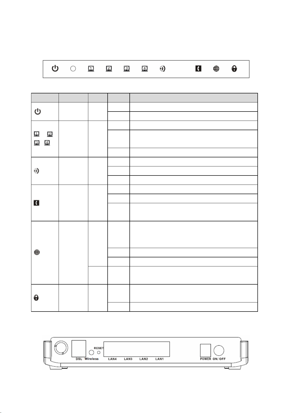
1.3 LED and Interfaces
Front Panel
The following table describes the LEDs of the device:
Indicator LED Color Status Description
/ /
/
Power Blue
LAN1-4 Blue
WLAN Blue
ADSL
Blue
Blue
On The device is started successfully.
Off The device is powered off.
On LAN connection is established and activated.
Blinks
Off The Ethernet interface is disconnected.
On WLAN is activated.
Blinks Data is being transmitted through the WLAN interface.
Off WLAN is not activated.
On The device is connected to the physical layer of the office.
Fast blinks The device is handshaking with the physical layer of the office.
Slowly
blinks
On
LAN data is being transmitted, or Internet data is being transmitted in
the bridge mode.
No signal is detected.
Connection to the Internet is established in the routing mode, for
example, PPP dialing is successful, and no data is being transmitted
through the Internet interface.
Rear Panel
Internet
Red On
Blinks Internet data is being transmitted in the routing mode.
Off The device is under the bridge mode.
Blinks
WPS Blue
Off WPS is not activated.
The device fails to connect to the Internet after synchronization in the
routing mode, for example, PPP dialing fails.
WPS is activated and the device is waiting for negotiation with the
clients.
2
Page 19
The following table describes the interfaces of the device:
Interface Function
DSL RJ-11 interface, for connecting to the ADSL interface or a splitter through a telephone cable.
Wireless Button to enable or disable WLAN.
RESET
LAN4/LAN3/
LAN2/LAN1
POWER Power interface, for connecting to the power adapter of 12 V DC, 1 A.
ON/OFF Power switch, power on or power off the device.
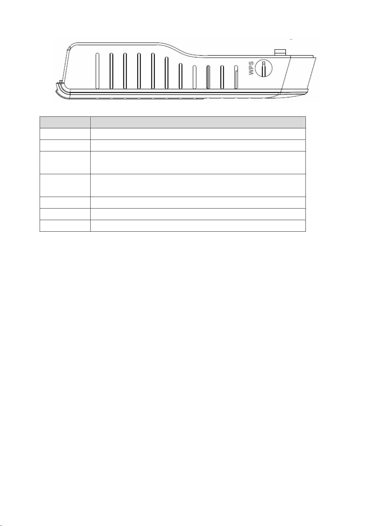
WPS (on the side) Press the button to enable the WPS service.
Restore to factory defaults. To restore factory defaults, keep the device powered on, and push
a paper clip into the hole to press the button for over 3 seconds and then release.
RJ-45 interface, for connecting to the Ethernet interface of a PC or the Ethernet devices
through an Ethernet cable.
1.4 System Requirements
Recommended system requirements are as follows:
A 10/100 base-T Ethernet card is installed on your PC
A hub or Switch (connected to several PCs through one of Ethernet interfaces on the device)
Operating system: Windows Vista, Windows XP, Windows 2000, Windows ME, or Windows 98SE
Internet Explorer V5.0 or higher, Netscape V4.0 or higher, or Firefox 1.5 or higher
1.5 Features
The device supports the following features:
Compatible with IEEE 802.11b/g/n standard
High-speed wireless data transfer
Various line modes
External PPPoE dial-up access
Internal PPPoE and PPPoA dial-up access
1483 Briged, 1483 Routed, and MER access
Multiple PVCs (up to eight) and these PVCs can be isolated from each other
A single PVC with multiple sessions
Multiple PVCs with multiple sessions
Binding of ports with PVCs
802.1Q and 802.1P protocol
DHCP server
3
Page 20

NAT and NAPT
Static route
Firmware upgrade: Web, TFTP, and FTP
Reset to factory defaults through the Reset button or Web
DNS relay
Virtual server
DMZ
Port Forwarding
Web interface
Telnet CLI
System status display
PPP session PAP and CHAP
IP filter
IP QoS
Remote access control
Line connection status test
Remote management (Telnet and HTTP)
Backup and restore of configuration file
Ethernet interface supports crossover detection, auto-correction and polarity correction
UPnP
Note:
When upgrading firmware by TFTP, you can not access the Web GUI temporarily until the upgrading
procedure has been finished and the device is rebooted.
4
Page 21
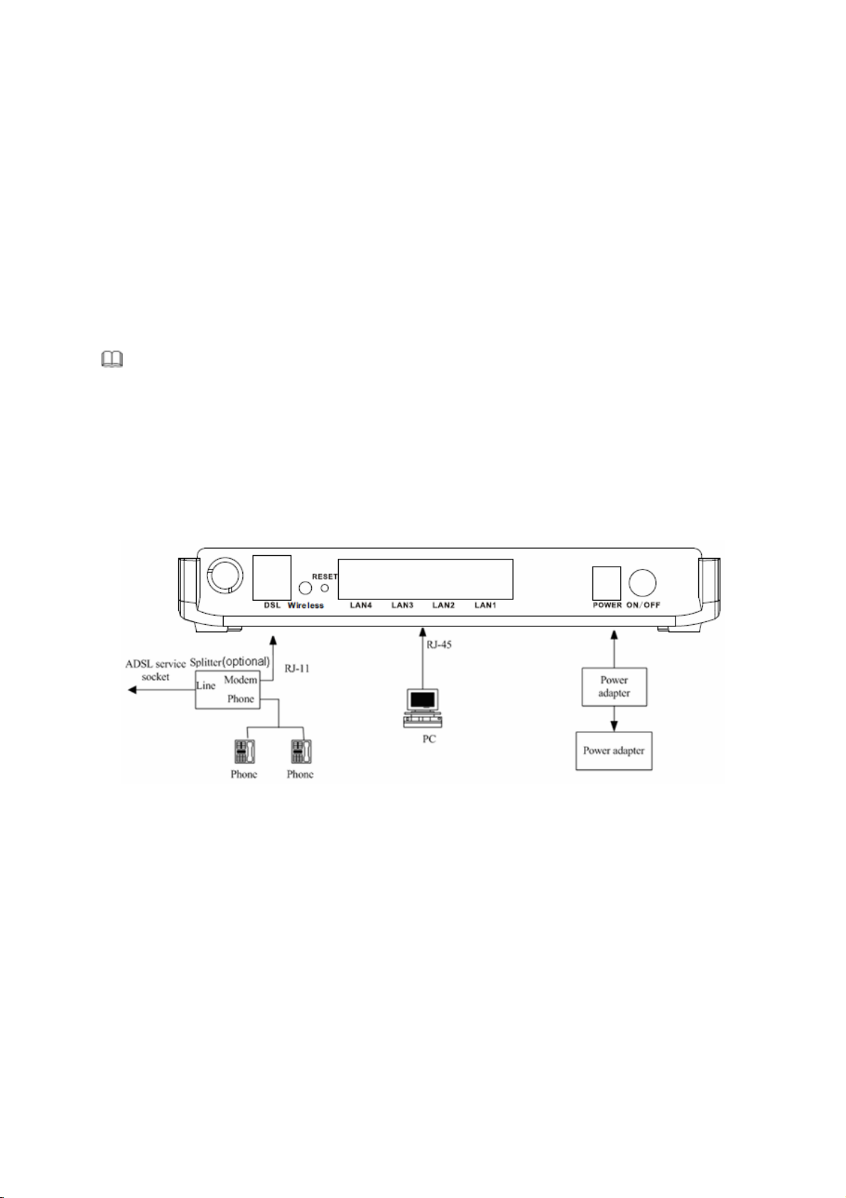
2 Hardware Installation
Step 1 Connect the DSL interface of the device to the MODEM interface of the splitter through a telephone cable.
Connect the phone to the PHONE interface of the splitter through a telephone cable. Connect the
incoming line to the LINE interface of the splitter.
The splitter has three interfaces:
LINE: Connect to a wall phone jack (RJ-11 jack).
MODEM: Connect to the ADSL jack of the device.
PHONE: Connect to a telephone set.
Step 2 Connect the LAN interface of the device to the network interface card (NIC) of the computer through an
Ethernet cable (MDI/MDIX).
I Note:
Use twisted-pair cables to connect with the hub or switch.
Step 3 Plug one end of the power adapter to the wall outlet and connect the other end to the POWER interface of
the device.
Connection 1
Figure 1 displays the application diagram for the connection of the router, computer, splitter and the telephone sets,
when no telephone set is placed before the splitter.
Figure 1 Connection diagram (Without connecting telephone sets before the splitter)
5
Page 22
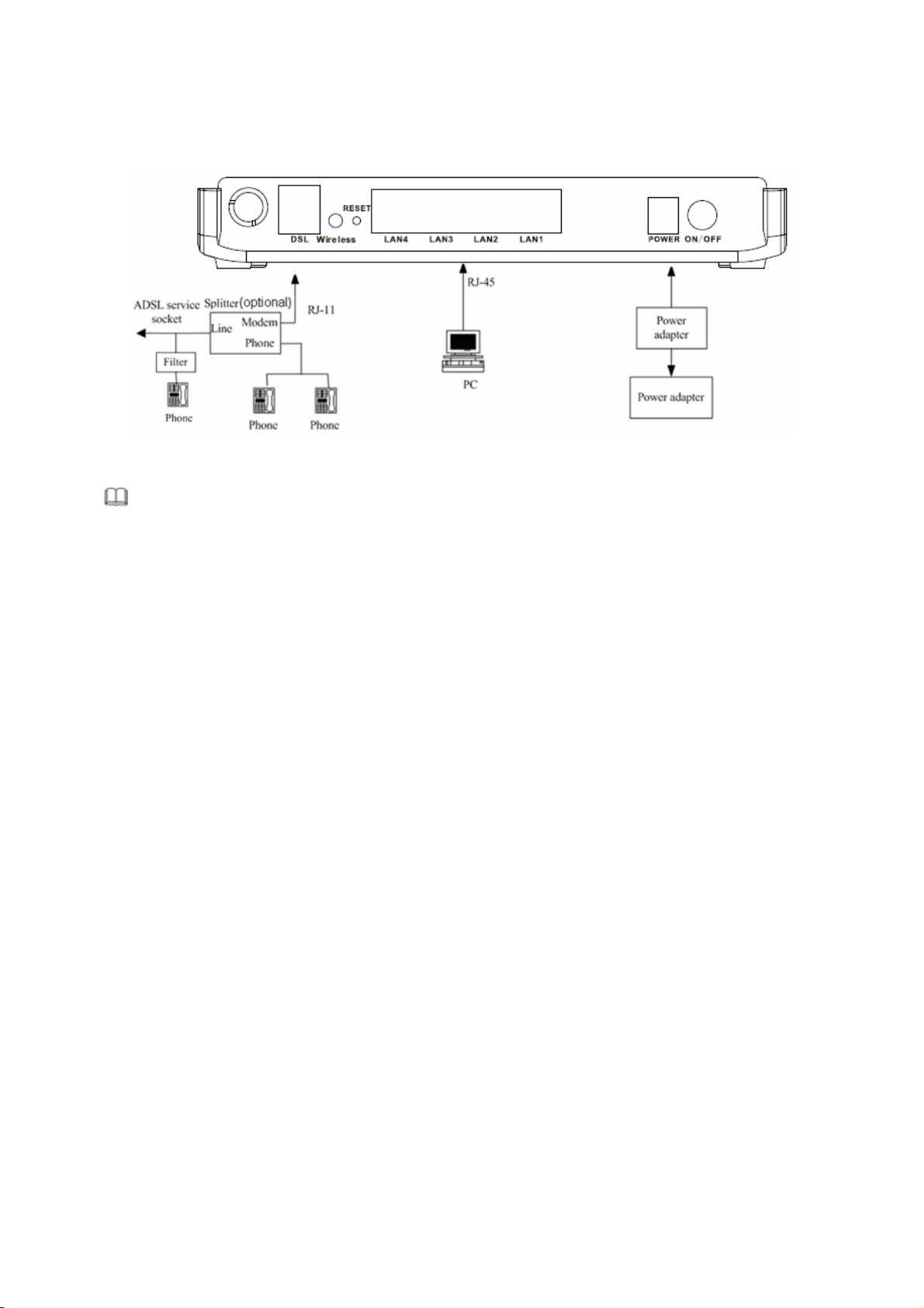
Connection 2
Figure 2 displays the connection when the splitter is installed close to the router.
Figure 2 Connection diagram (Connecting a telephone set before the splitter)
Note:
When connection 2 is used, the filter must be installed close to the telephone cable. See Figure2. Do not use
the splitter to replace the filter.
Installing a telephone directly before the splitter may lead to failure of connection between the device and the
central office, or failure of Internet access, or slow connection speed. If you really need to add a telephone set
before the splitter, you must add a microfilter before a telephone set. Do not connect several telephones before the
splitter or connect several telephones with the microfilter.
6
Page 23
3 About the Web Configuration
This chapter describes how to configure the router by using the Web-based configuration utility.
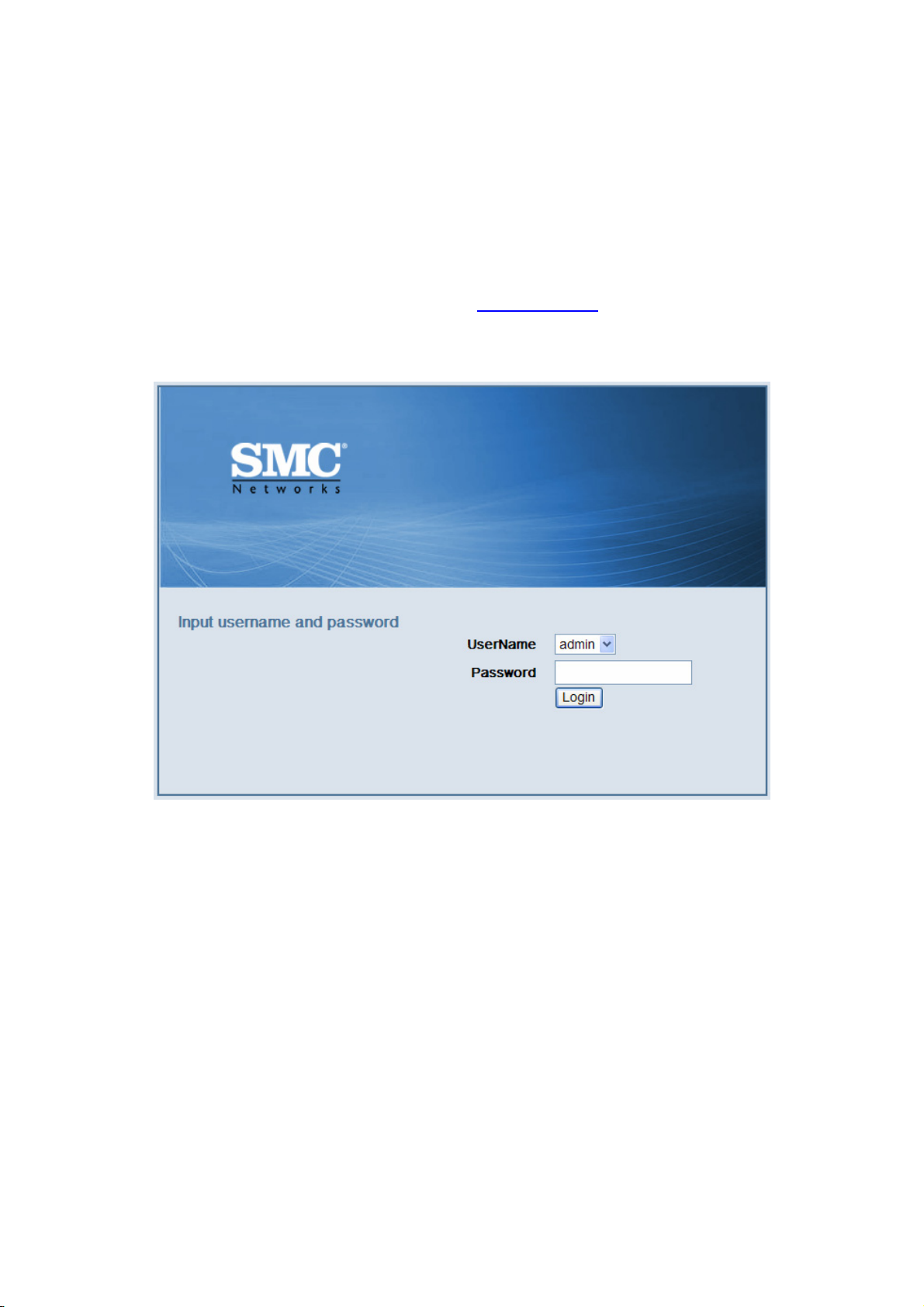
3.1 How to Access the Router
The following is the detailed description of accessing the router for the first time.
Step 1 Open the Internet Explorer (IE) browser and enter http://192.168.2.1
Step 2 In the Login page that is displayed, enter the username and password.
The username and password of the super user are admin and smcadmin.
.
If you log in as the super user, the page as shown in the following figure appears. You can check, configure and
modify all the settings.
7
Page 24
Caution:
If the device is not in use, please power off the device.
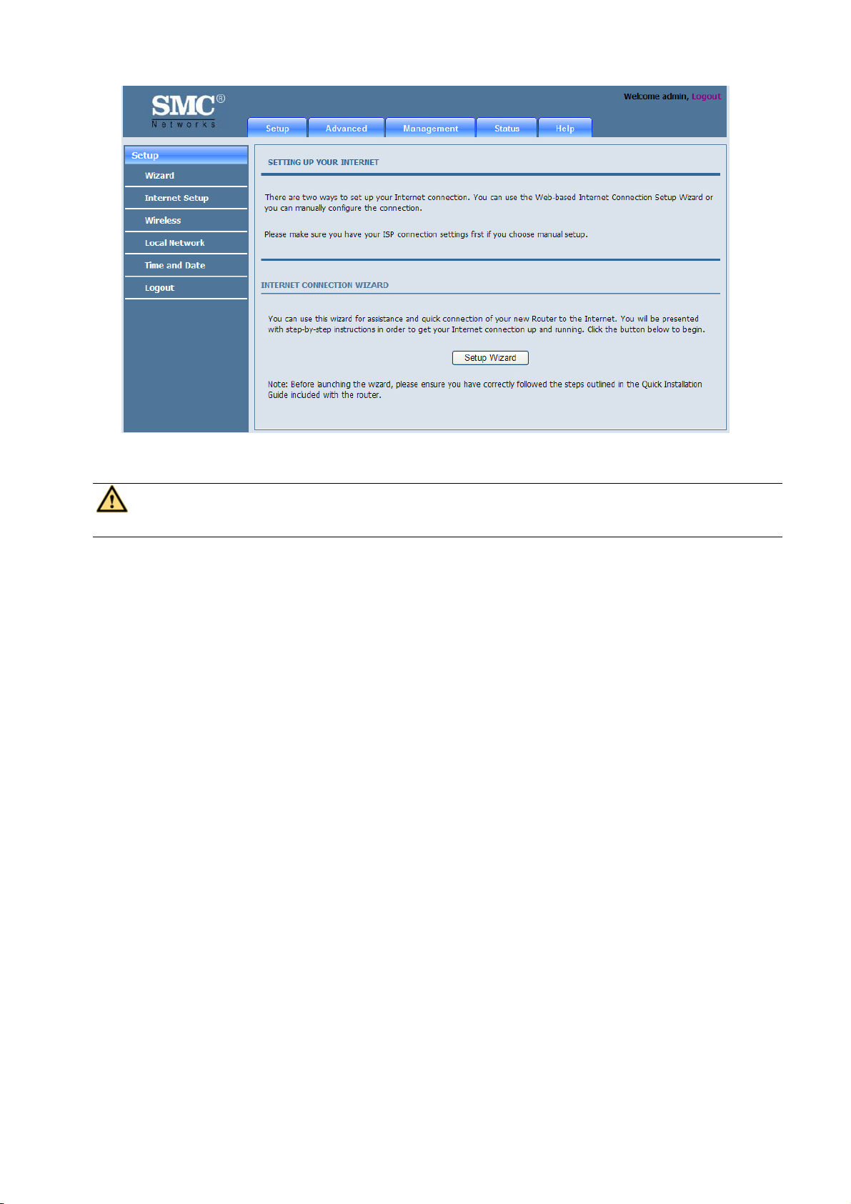
3.2 Setup Wizard
Setup Wizard helps you to fast and accurately configure Internet connection and other important parameters. The
following sections describe these various configuration parameters.
When subscribing to a broadband service, be aware of the Internect connection mode. The physical WAN device
can be Ethernet, DSL, or both. Technical information about properties of Internet connection is provided by your
Internet service provider (ISP). For example, your ISP should inform you whether you are connected to the Internet
using a static or dynamic IP address, and the protocol, such as PPPoA or PPPoE, that you use to communicate on
the Internet.
8
Page 25
Step 1 Choose Setup > Wizard. The page as shown in the following figure appears:
Step 2 Click Setup Wizard. The page as shown in the following figure appears:
There are four steps to configure the device. Click Next to continue.
9
Page 26
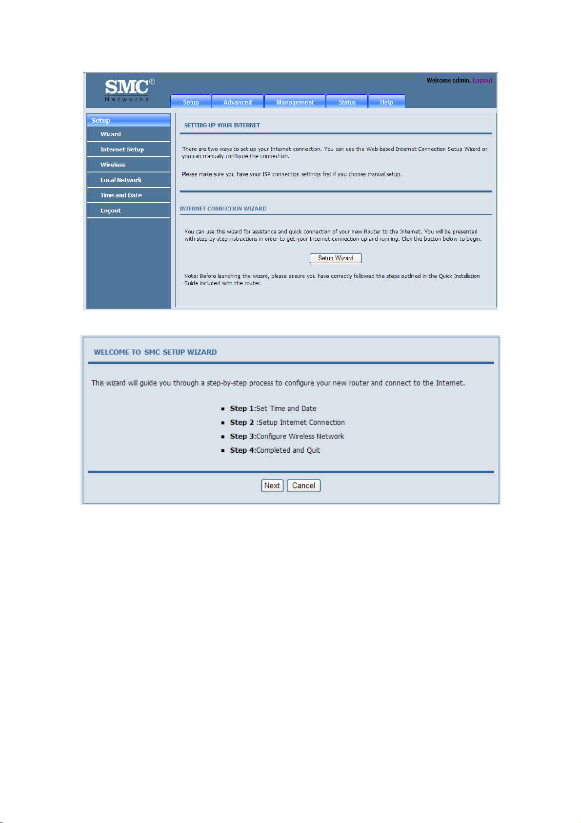
Step 3 Set the time and date. Then, click Next.
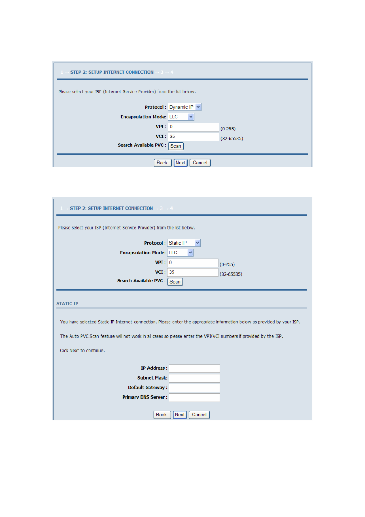
Step 4 Configure the Internet connection.
Select the protocol and the encapsulation mode. Set the VPI and the VCI.
If the Protocol is set to PPPoE or PPPoA, the page as shown in the following figure appears:
10
Page 27
You need to enter the user name and password provided by your ISP for PPPoE or PPPoA dialup.
If the Protocol is set to Dynamic IP, the page as shown in the following figure appears:
If the Protocol is set to Static IP, the page as shown in the following figure appears:
You need to enter the information of the IP address, subnet mask, and gateway that provided by your ISP.
If the Protocol is set to Bridge, the page as shown in the following figure appears:
11
Page 28
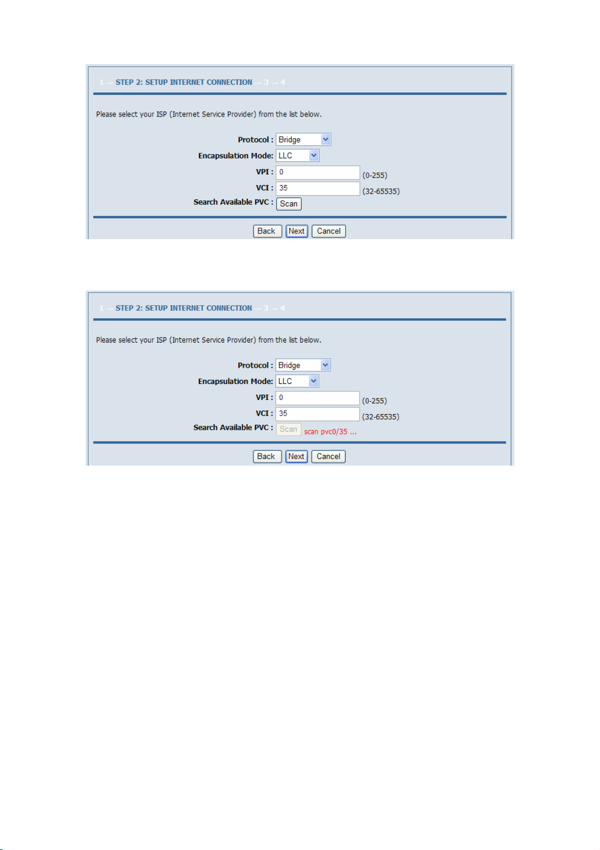
If you click Scan, the system automatically searches the available PVCs.
After setting, click Next.
Step 5 Configure the wireless network. Enter the information and click Next.
12
Page 29

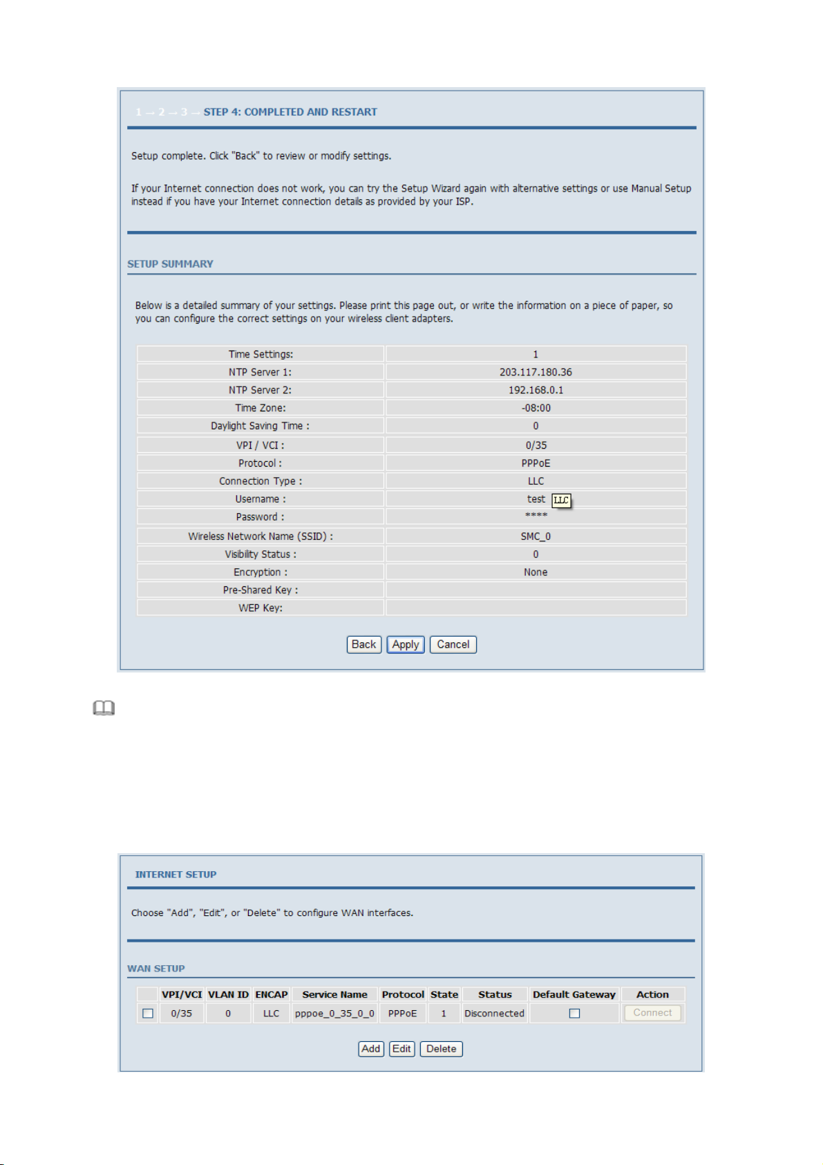
Step 6 View the configuration information of the device. To modify the information, click Back. To effect the
configuration, click Apply.
13
Page 30
Note:
In each step of the Wizard page, you can click Back to review or modify the previous settings or click
Cancel to exit the wizard.
3.2.1 Internet Setup
Choose Setup > Internet Setup. The page as shown in the following figure appears:
14
Page 31

In this page, you can configure the WAN interface of the device.
Click Add and the page as shown in the following figure appears:
The following table describes the parameters in this page.
Field Description
ATM PVC CONFIGURATION
VPI
VCI
Service Category
Peak Cell Rate Set the maximum transmission rate of the cell in ATM transmission.
Sustainable Cell Rate Set the minimum transmission rate of the cell in ATM transmission.
Maximum Burst Size Set the maximum burst size of the cell in ATM transmission.
CONNECTION TYPE
Protocol
Virtual Path Identifier (VPI) is the virtual path between two points in an ATM network. Its
value range is from 0 to 255.
Virtual Channel Identifier (VCI) is the virtual channel between two points in an ATM
network. Its value range is from 32 to 65535 (0 to 31 is reserved for local management of
ATM traffic).
Select UBR with PCR, UBR without PCR, CBR, Non Real-time VBR, or Real-time VBR
from the drop-down list.
Select PPP over ATM (PPPoA), PPP over Ethernet (PPPoE), MAC Encryption Routing
(MER), IP over ATM (IPoA), or Bridging from the drop-down list.
15
Page 32

Field Description
Encapsulation Mode
802.1Q VLAN ID
NETWORK ADDRESS TRANSLATION SETTINGS
Enable Bridge Service Select or deselect the check box to enable or disable the WAN connection.
Service Category The name to identify the WAN connection. You need not modify it.
Select LLC or VCMUX from the drop-down list. Usually, you can select LLC.
If you enter a value, packets from the interface is tagged with the set 802.1q VLAN ID. Its
value range is 0-4094, while 0 indicates to disable this function.
PPPoE/PPPoA
If you select the PPPoE or PPPoA as the connection protocol, the following page appears.
PPP Username: The correct user name that your ISP provides to you.
PPP Password: The correct password that your ISP provides to you.
Authentication Method: You can select it from the drop-down list. The default value is AUTO.
Use Static IP Address: If this function is disabled, the modem obtains an IP address assigned by an uplink
equipment such as BAS, through PPPoE dial-up.If this function is enabled, the modem uses this IP address as the
WAN IP address.
MER
If you select the MER as the connection protocol, the following page appears.
16
Page 33

IPoA
If you select the IPoA as the connection protocol, the following page appears.
After proper configurations, click Apply to take the settings in to effect.
17
Page 34

3.2.2 Wireless Setup
This section describes the wireless LAN and some basic configuration. Wireless LANs can be as simple as two
computers with wireless LAN cards communicating in a pear-to-pear network or as complex as a number of
computers with wireless LAN cards communicating through access points that bridge network traffic to a wired
LAN.
Choose Setup > Wireless. The WIRELESS SETTINGS page as shown in the following figure appears:
3.2.2.1 Wireless Basics
In the WIRELESS SETTINGS page, click Wireless Basic. The page as shown in the following figure appears:
In this page, you can configure the parameters of wireless LAN clients that may connect to the device.
The following table describes the parameters in this page.
Field Description
Enable Wireless Select or deselect the check box to enable or disable the wireless function.
Enable MultiAP Isolation
Wireless Network Name (SSID)
Visibility Status
Country Select the country where you are in from the drop-down list.
Select or deselect the check box to enable or disable multiAP isolation. If this function is
enabled, clients of different SSIDs cannot access each other.
Network name. It can contain up to 32 characters. It can consist of letters, numerals,
and/or underlines.
Visible indicates that the device broadcasts the SSID.
Invisible indicates that the device does not broadcast the SSID.
18
Page 35

Field Description
Select the wireless channel used by the device from the drop-down list. You can select
Wireless Channel
802.11 Mode
Band Width
Auto Scan or a value from the drop-down list. The value is different for different
country.
Select the 802.11 mode of the device from the drop-down list. The device supports
802.11b, 802.11g, 802.11n, 802.11b/g, 802.11n/g, and 802.11b/g/n.
You can set the bandwidth only in the 802.11n mode. You can set the bandwidth of the
device to 20M or 40M.
Click Apply to save the settings.
3.2.2.2 Wireless Security
In the WIRELESS SETTINGS page, click Wireless Security. The page as shown in the following figure appears:
Wireless security is vital to your network to protect the wireless communication among wireless stations, access
points and the wired network. This device provides the following encryption modes: None, WEP, Auto (WPA or
WPA2), WPA2 Only, and WPA Only.
WEP
If the Security Mode is set to WEP, the page as shown in the following figure appears:
19
Page 36

The following table describes the parameters in this page.
Field Description
You can select 64 bits or 128 bits from the drop-down list.
WEP Key Length
Choose WEP Key Select the WEP key from the drop-down list. Its value range is 1—4.
WEP Keys 1—4 Set the 64 bits or 128 bits key, in the format of Hex or ASCII.
If you select 64 bits, you need to enter 10 hexadecimal numbers or 5 characters.
If you select 128 bits, you need to enter 26 hexadecimal numbers or 13 characters.
Authentication
Select the authentication mode from the drop-down list. You can select Open or Share
Key.
Click Apply to save the settings.
Auto (WPA or WPA2)
If the Security Mode is set to Auto (WPA or WPA2), the page as shown in the following figure appears:
20
Page 37

The following table describes the parameters in this page.
Field Description
WPA Mode
Group Key Update Interval Set the interval for updating the key.
Pre-Shared Key Set the preshared key to identify the workstation.
You can select Auto (WPA or WPA2)-PSK or Auto (WPA or WPA2)-Enterprise
from the drop-down list.
If the WPA Mode is set to Auto (WPA or WPA2)-Enterprise, the page as shown in the following figure appears:
21
Page 38

You need to enter the IP address, port, shared key of the RADIUS server.
Click Apply to save the settings.
WPA2 Only
If the Security Mode is set to WPA2 only, the page as shown in the following figure appears:
22
Page 39

Parameters in this page are similar to those in the page for Auto (WPA or WPA2).
Click Apply to save the settings.
WPA Only
If the Security Mode is set to WPA only, the page as shown in the following figure appears:
23
Page 40

Parameters in this page are similar to those in the page for Auto (WPA or WPA2).
Click Apply to save the settings.
3.2.3 Local Network
You can configure the LAN IP address according to the actual application. The preset IP address is 192.168.1.1.
You can use the default settings and DHCP service to manage the IP settings of the private network. The IP address
of the device is the base address used for DHCP. To use the device for DHCP in your LAN, the IP address pool
used for DHCP must be compatible with the IP address of the device. The IP address available in the DHCP IP
address pool changes automatically if the IP address of the device changes.
You can also enable the secondary LAN IP address. The primary and the secondary LAN IP addresses must be in
different network segments.
Choose Setup > Local Network. The LOCAL NETWORK page as shown in the following figure appears:
By default, Enable DHCP Server is selected for the LAN interface of the device. DHCP service provides IP
settings to workstations configured to automatically obtain IP settings that are connected to the device through the
Ethernet port. When the device is used for DHCP, it becomes the default gateway for DHCP client connected to it.
24
Page 41

If you change the IP address of the device, you must also change the range of IP addresses in the pool used for
DHCP on the LAN. The IP address pool can contain up to 253 IP addresses.
Click Apply to save the settings.
In the LOCAL NETWORK page, you can assign LAN IP addresses for specific computers according to their
MAC addresses.
Click Add to add static DHCP reservation. The page as shown in the following figure appears:
The following table describes the parameters in this page.
Field Description
Enable
Computer Name
IP Address Enter the IP address of the computer.
MAC Address Enter the MAC address of the computer.
Select the check box to reserve the IP address for the designated PC with the configured
MAC address.
Enter the computer name. It helps you to recognize the PC with the MAC address. For
example, Father’s Laptop.
Click Apply to save the settings.
After the DHCP reservation information is saved, the DHCP reservations list displays the information.
If the DHCP reservations list is not empty, you can select one or more items and click Edit or Delete.
The NUMBER OF DYNAMIC DHCP CLIENTS page displays the DHCP clients (PCs or Laptops) currently
connected to the device and the detailed information of the connected computers.
25
Page 42

3.2.4 Time and Date
Choose Setup > Time and Date. The TIME AND DATE page as shown in the following figure appears:
In the TIME AND DATE page, you can configure, update, and maintain the time of the internal system clock. You
can set the time zone that you are in and the network time protocol (NTP) server. You can also set daylight saving
time to automatically adjust the time when needed.
Select Automatically synchronize with Internet time servers.
Select the appropriate time server and the time zone from the corresponding drop-down lists.
Select Enable Daylight Saving if necessary. Enter the correct the start and end time of the daylight saving.
Click Apply to save the settings.
3.2.5 Logout
Choose Setup > Logout. The page as shown in the following figure appears:
Click Logout to log out of the configuration page.
26
Page 43
3.3 Advanced Configuration
This section contains advanced features used for network management, security and administrative tools to manage
the device. You can view the status and other information of the device, to examine the performance and
troubleshoot.
3.3.1 Advanced Wireless
This function is used to modify the standard 802.11g wireless settings. It is recommended not changing the default
settings, because incorrect settings may affect the performance of the wireless performance. The default settings
provide the best wireless performance in most environments.
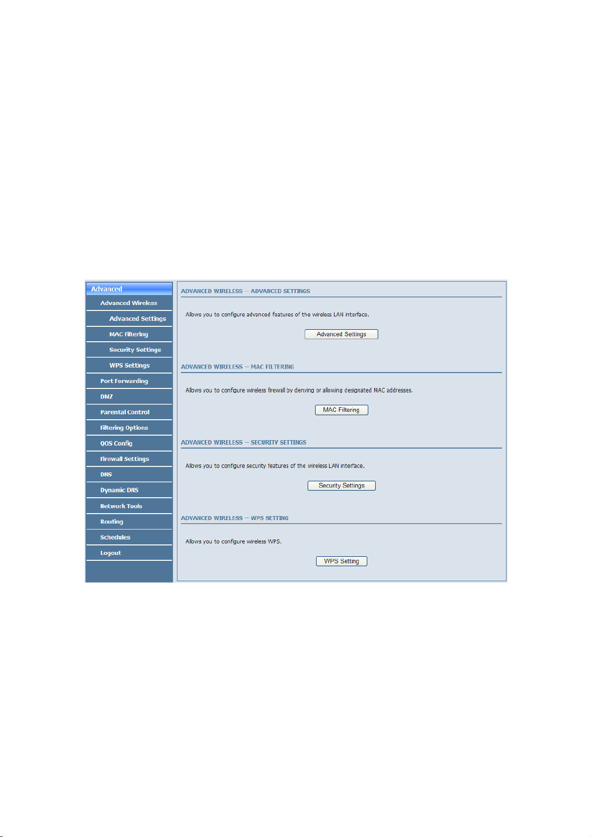
Choose Advanced > Advanced Wireless. The ADVANCED WIRELESS page as shown in the following figure
appears:
27
Page 44

3.3.1.1 Advanced Settings
In the ADVANCED WIRELESS page, click Advanced Settings. The page as shown in the following figure
appears:
28
Page 45

The following table describes the parameters in this page.
Field Description
ADVANCED WIRELESS SETTINGS
Transmission Rate Select the transmission rate of the wireless network from the drop-down list.
Multicast Rate
Transmit Power
Beacon Period
RTS Threshold
Fragmentation Threshold Its value range is 256—2346 and the default value is 2345.
DTIM Interval
Preamble Type
SSID
Enable Wireless Select or deselect the check box to enable or disable the wireless function.
SSID
Visibility Status
User Isolation
Disable WMM Advertise
Max Clients
SSID-1—3
Enable Wireless Guest Network Select or deselect the check box to enable or disable the wireless interface.
SSID Similar to the primary SSID, it identifies a wireless AP.
Select the multicast transmission rate of the wireless network from the drop-down list.
You can select Lower or Higher.
Select the power for data transmission from the drop-down list. You can select 100%,
80%, 60%, 40%, or 20%.
By default, the wireless beacon frame sends the data once every 100ms. Its value range is
20—1024.
The threshold of transmission request. Its value range is 0—2347 and the default value is
2346.
Data beacon proportion (transmission quantity indication). Its value range is 1—255 and
the default value is 100.
Select the preamble code from the drop-down list. You can select long or short.
Set the wireless network name, that is, SSID. SSID is used to distinguish different
wireless networks.
Select whether to hide the AP. You can select Visible or Invisible. If you select Invisible,
the AP is hidden and the terminal cannot obtain the SSID through passive scanning.
Select whether users of the AP can communicate with each other. You can select Off or
On from the drop-down list. On indicates that computers connected to the device cannot
communicate with each other.
Select whether to disable WMM. You can select Off or On.
Set the maximum number of clients that can be connected to the AP at the same time. Its
value range is 1—32.
These settings are applicable only for more technically advanced users who have sufficient knowledge about
wireless LAN. Do not change these settings unless you know the effect of changes on the device.
Click Apply to save the settings.
29
Page 46
3.3.1.2 MAC Filtering
In the ADVANCED WIRELESS page, click MAC Filtering. The page as shown in the following figure appears:
Click Add and the page as shown in the following figure appears:
The following table describes the parameters in this page.
Field Description
User Name
Current PC’s MAC Address Enter the MAC address of the computer that connects to the device.
Other MAC Address Enter the MAC address of another device that is included in MAC filtering.
Schedule
Manual Schedule If you select this check box, you need to manually set the time of MAC filtering.
Enter the name that identifies your configuration. For example, kids.
Select the time of MAC filter from the drop-down list. You can select always or never.
Click Apply to save the settings.
30
Page 47

3.3.1.3 Security Settings
In the ADVANCED WIRELESS page, click Security Settings. The page as shown in the following figure appears:
Select the desired SSID from the drop-down list.
Select the encryption type from the Security Mode drop-down list. You can select None, WEP, AUTO (WPA or
WPA2), WPA Only, or WPA2 Only. For parameters of different encryption types, see section 3.2.2.2 "Wireless
Security”.
Click Apply to save the settings.
3.3.1.4 WPS Settings
In the ADVANCED WIRELESS page, click WPS Setting. The WIRELESS WPS page as shown in the
following figure appears:
Enabled: The WPS service is enabled by default.
31
Page 48

Note:
Ensure that the network card supports the WPS function.
You can use one of the following there methods to use WPS authentication:
Press the WPS button on the side panel for 3 seconds.
In the WIRELESS WPS page, click PBC. It has the same function of the WPS button on the side panel. This
is an optional method on wireless clients.
Note:
You need a Registrar when using the PBC method in a special case in which the PIN is all zeros.
In the WIRELESS WPS page, enter the PIN code provided by the station and click PIN. PIN entry is a
mandatory method of setup for all WPS certified devices.
Note:
If you are using the PIN method, you need a Registrar, either an access point or a wireless router, to
initiate the registration between a new device and an active access point or a wireless router.
3.3.2 Port Forwarding
This function is used to open ports in your device and re-direct data through these ports to a single PC in your
network (WAN-to-LAN traffic). It allows remote users to access services in your LAN, such as FTP for file
transfers or SMTP, and POP3 for e-mail. The device receives remote requests for these services at your public IP
address. It uses the specified TCP or UDP protocol and port, and redirects these requests to the server on your LAN
with the specified LAN IP address. Note that the specified private IP address must be within the available IP
address range of the subnet where the device is in.
Choose Advanced > Port Forwarding. The page as shown in the following figure appears:
Click Add to add a virtual server. See the following figure:
32
Page 49

Select a service for a preset application or enter the name in the Custom Server field.
Enter an IP address in the Server IP Address field, to appoint the corresponding PC to receive forwarded packets.
The port table displays the ports that you want to open on the device. The Protocol indicates the type of protocol
used by each port. Click Apply to save the settings.
3.3.3 DMZ
Choose Advanced > DMZ. The page as shown in the following figure appears:
33
Page 50

In this page, you can enable a DMZ host. In this way, access from Internet to the WAN IP address of the device is
forwarded to the DMZ host and network server of the internal LAN is protected.
Click Apply to save the settings.
3.3.4 Parental Control
Choose Advanced > Parental Control. The PARENTAL CONTROL page as shown in the following figure
appears:
This page provides two useful tools for restricting Internet access. Block Website allows you to quickly create a list
of websites that you wish to prevent users from accessing. Block MAC Address allows you to control Internet
access by clients or PCs connected to the device.
3.3.4.1 Block Website
In the PARENTAL CONTROL page, click Block Website. The page as shown in the following figure appears:
Click Add. The page as shown in the following page appears:
34
Page 51

Enter the website in the URL field. Select the time to block websites from the Schedule drop-down list, or select
Manual Schedule and set the corresponding time and days.
Click Apply to add the website to the BLOCK WEBSITE table.
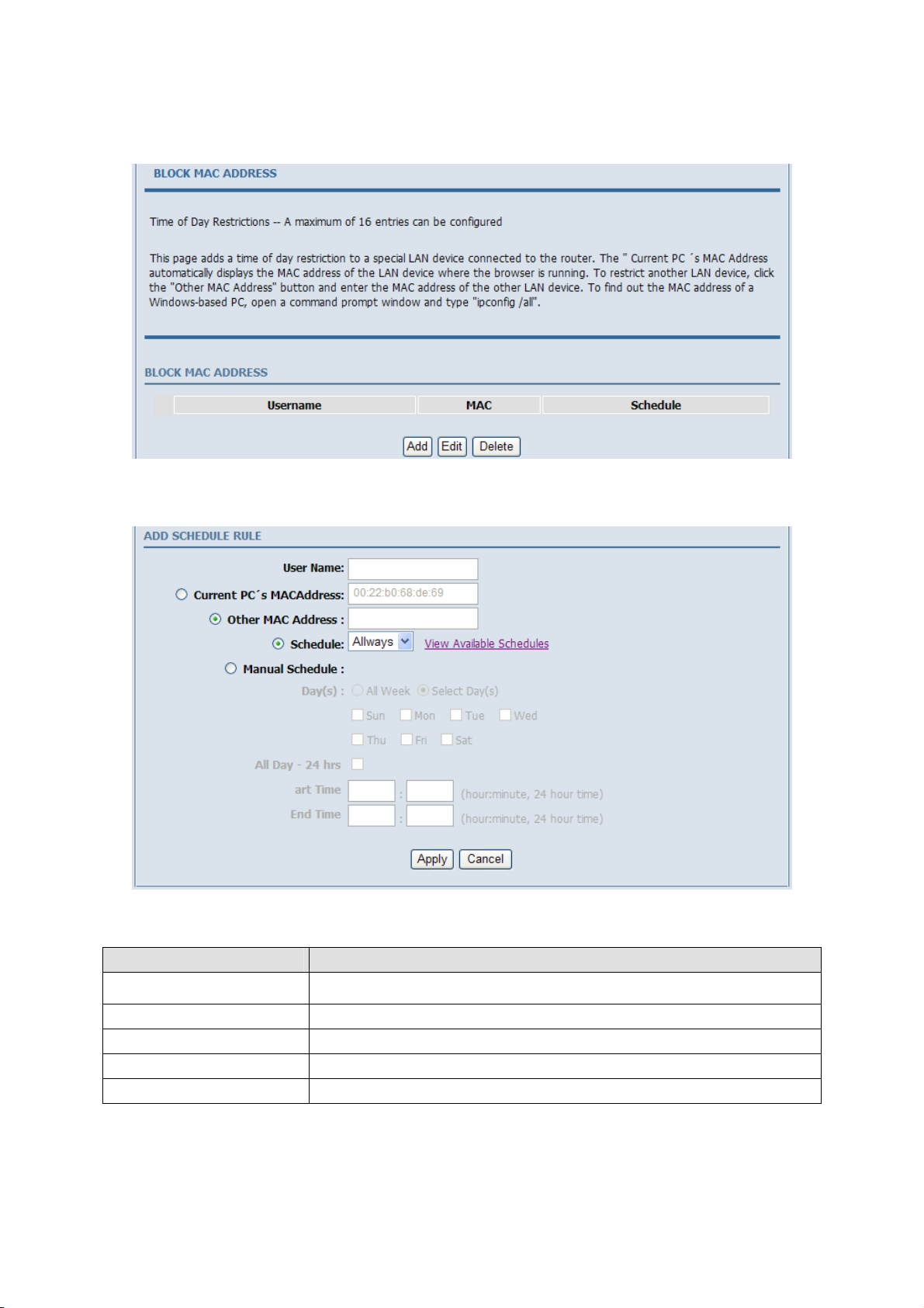
3.3.4.2 Block MAC Address
In the PARENTAL CONTROL page, click Block MAC Address. The page as shown in the following figure
appears:
Click Add. The page as shown in the following figure appears:
35
Page 52

The following table describes the parameters in this page.
Field Description
User Name
Current PC’s MAC Address Enter the MAC address of the computer that connects to the device.
Other MAC Address Enter the MAC address of another device that is included in MAC filtering.
Schedule
Manual Schedule If you select this check box, you need to manually set the time of MAC filtering.
Enter the name that identifies your configuration. For example, kids.
Select the time of MAC filter from the drop-down list. You can select always or never.
Enter the use name and MAC address. Select the corresponding time and days. Then, click Apply to add the MAC
address to the BLOCK MAC ADDRESS table.
3.3.5 Filtering Options
Choose Advanced > Filtering Options. The FILTERING OPTIONS page as shown in the following figure
appears:
36
Page 53

3.3.5.1 Inbound IP Filtering
In the FILTERING OPTIONS page, click Inbound IP Filtering. The INCOMING IP FILTERING page as
shown in the following figure appears:
Click Add to add an inbound IP filter. The page as shown in the following figure appears:
Enter the Filter Name and specify at least one of the following criteria: protocol, source/destination IP address,
subnet mask, and source/destination port.
Then, click Apply to save the settings.
Note:
The settings apply only when the firewall is enabled.
The ACTIVE INBOUND FILTER in the INCOMING IP FILTERING page displays detailed information of
each created inbound IP filter. Click Delete to delete an IP filter. Note that the Delete button appears only when at
least one IP filter exists.
37
Page 54

3.3.5.2 Outbound IP Filtering
By default, all outgoing IP traffic from the LAN is allowed. The outbound filter allows you to create a filter rule to
block outgoing IP traffic by specifying a filter name and at least one criterion.
In the FILTERING OPTIONS page, click Outbound IP Filtering. The OUTGOING IP FILTERING page as
shown in the following figure appears:
Click Add to add an outbound IP filter. The page as shown in the following figure appears:
Enter the Filter Name and specify at least one of the following criteria: protocol, source/destination IP address,
subnet mask, and source/destination port. Click Apply to save the settings.
The ACTIVE OUTBOUND FILTER in the OUTGOING IP FILTERING page displays detailed information
OF each created outbound IP filter. Click Delete to delete an IP filter. Note that the Delete button appears only
when at least one IP filter exists.
38
Page 55
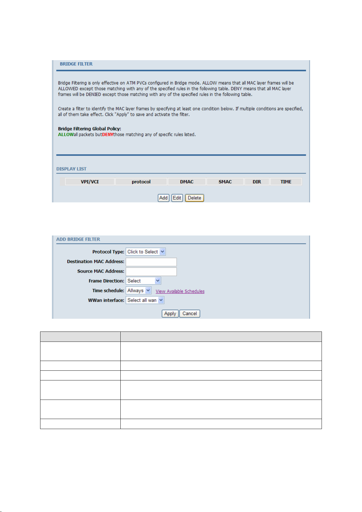
3.3.5.3 Bridge Filtering
In the FILTERING OPTIONS page, click Bridge Filtering. The page as shown in the following figure appears:
This page is used to configure bridge parameters. In this page, you can modify the settings or view the information
of the bridge and its attached ports.
Click Add to add a bridge filter. The page as shown in the following figure appears:
The following table describes the parameters in this page.
Field Description
Protocol Type
Destination MAC Address Enter the destination MAC address to be mapped.
Source MAC Address Enter the source MAC address to be mapped.
Frame Direction
Time schedule
Wan interface Select the WAN interface to be mapped from the drop-down list.
Select the protocol type to be mapped from the drop-down list. You can select PPPoE,
IPv4, IPv6, AppleTalk, IPX, NetBEUI, or IGMP.
Select the frame direction to be mapped from the drop-down list. The device supports
frame direction from LAN to WAN and that from WAN to LAN.
Select the time that you want to apply the rule from the drop-down list. You can select
always or never.
Click Apply to save the settings.
39
Page 56

3.3.6 QoS Config
Choose Advanced > QoS Config. The page as shown in the following figure appears:
3.3.6.1 Interface Configuration
In the QoS CONFIG page, click QoS Interface Config. The page as shown in the following figure appears:
Click Edit and the page as shown in the following figure appears:
In this page, you can configure the uplink bandwidth and downlink bandwidth of each interface. The uplink rate
and the downlink rate are limited according to the configured bandwidth. Click Apply to save the settings.
40
Page 57

3.3.6.2 Queue Configuration
In the QoS CONFIG page, click QoS Queue Config. The page as shown in the following figure appears:
In this page, you can configure the priority of the queue. The device supports the following three priority levels:
high, medium, low. The device handles packets of the high queue priority first, then packets of medium, and
finally packets of low priority. Click Add. The page as shown in the following figure appears:
Click Apply to save the settings.
3.3.6.3 Classification Configuration
In the QoS CONFIG page, click QoS Classify Configuration. The page as shown in the following figure appears:
This page displays the classes. Click Add and the page as shown in the following figure appears:
41
Page 58

The following table describes the parameters in this page.
Field Description
Traffic Class Name Enter the name of the traffic class.
Enable Classification Select or deselect the check box to enable or disable QoS classification.
SPECIFY TRAFFIC CLASSIFICATION RULES
Select L1&L2 or L3&L4 from the drop-down list.
Classification Type
Physical Lan Port
Source MAC Address Enter the source MAC address of the packet.
Source MAC Mask
Destination MAC Address Enter the destination MAC address of the packet.
Destination MAC Mask
Ethernet Type
802.1p Priority
SPECIFIC TRAFFIC CLASSIFICATION RESULT
Assign Classification Queue Specify the queue to which the packet belongs. You can set the queue in the classification
L1&L2 maps to the features of layer 1 and layer 2, such as the MAC address.
L3&L4 maps to the features of layer 3 and layer 4, such as the IP address and the port.
Select the physical port of the packet from the drop-down list. For example, ethernet1,
ethernet2, ethernet3, and ethernet4.
Use mask 000000ffffff to mask the MAC address. 00 indicates not mapped and ff
indicates mapped.
Use mask 000000ffffff to mask the MAC address. 00 indicates not mapped and ff
indicates mapped
Select the layer 2 protocol type from the drop-down list. For example, IP protocol and
IPX protocol.
Select the 802.1p priority of the packet from the drop-down list. You can select no match
or a value in the range of 0—7. Note that this function is not supported at the moment.
42
Page 59

Field Description
configuration.
Mark DSCP Attach the DSCP mark to the mapped packet.
Mark 802.1p Priority Attach the 802.1p mark to the mapped packet.
Click Apply to save the settings.
3.3.7 Firewall Settings
A denial-of-service (DoS) attack is one of the most common network attacks and is characterized by an explicit
attempt by attackers to prevent legitimate users of a service from using that service. It usually leads to overload of
system server or core dump of the system.
Choose Advanced > Firewall Settings. The page as shown in the following figure appears:
Click Apply to save the settings.
3.3.8 DNS
Domain name system (DNS) is an Internet service that translates domain names into IP addresses. Because domain
names are alphabetic, they are easier to remember. The Internet, however, is actually based on IP addresses. Each
time you use a domain name, a DNS service must translate the name into the corresponding IP address. For
example, the domain name www.example.com might be translated to 198.105.232.4.
The DNS system is, in fact, its own network. If one DNS server does not know how to translate a particular domain
name, it asks another one, and so on, until the correct IP address is returned.
Choose Advanced > DNS. The page as shown in the following figure appears:
43
Page 60
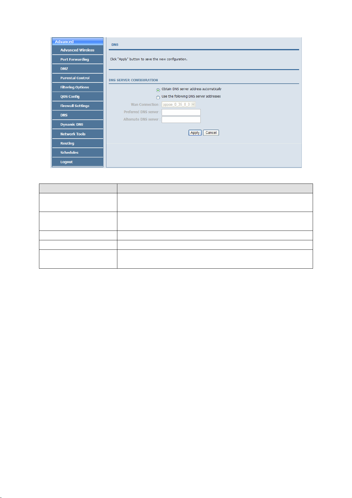
The following table describes the parameters in this page.
Field Description
Obtain DNS server address
automatically
Use the following DNS server
addresses
WAN Connection Select the WAN interface of the DNS server to be connected from the drop-down list.
Preferred DNS server Enter the IP address of the primary DNS server.
Alternate DNS server
If you select this radio button, the device automatically obtains IP address of the DNS
server from the ISP. You need not manually enter the IP address of the server.
If you select this radio button, you need to manually enter the IP address of the server
provided by the ISP.
Enter the IP address of the secondary DNS server. If the primary DNS server fails to
work, the device tries to connect the secondary DNS server.
Click Apply to save the settings.
3.3.9 Dynamic DNS
The device supports dynamic domain name service (DDNS). The dynamic DNS service allows a dynamic public IP
address to be associated with a static host name in any of the many domains, and allows access to a specified host
from various locations on the Internet. Click a hyperlinked URL in the form of hostname.dyndns.org and allow
remote access to a host. Many ISPs assign public IP addresses using DHCP, so locating a specific host on the LAN
using the standard DNS is difficult. For example, if you are running a public web server or VPN server on your
LAN, DDNS ensures that the host can be located from the Internet even if the public IP address changes. DDNS
requires that an account be set up with one of the supported DDNS service providers (DyndDNS.org or
Dlinkddns.com).
Choose Advanced > Dynamic DNS. The page as shown in the following page appears:
44
Page 61
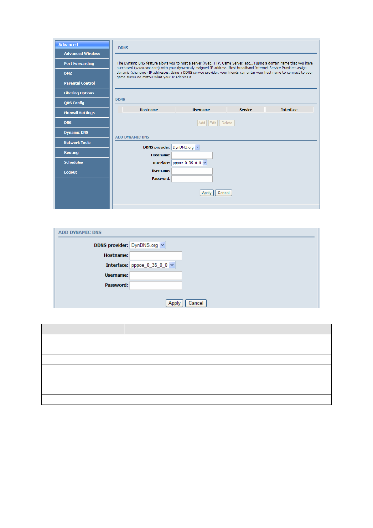
Click Add to add dynamic DNS. The page as shown in the following figure appears:
The following table describes the parameters in this page.
Field Description
DDNS provider
Hostname Enter the host name that you register with your DDNS provider.
Interface
Username Enter the user name of your DDNS account.
Password Enter the password of your DDNS account.
Select the DDNS provider from the drop-down list. You can select DynDns.org, TZO, or
GnuDIP.
Select the interface that is used for DDNS service from the drop-down list. The IP
address of the interface corresponds to the host name.
Click Apply to save the settings.
3.3.10 Network Tools
Choose Advanced > Network Tools. The NETWORK TOOLS page as shown in the following figure appears:
45
Page 62

46
Page 63

This page contains the following function items: port mapping, IGMP proxy, IGMP snooping, , UPnP, ADSL,
SNMP, TR-069, certificates and pptpd.
3.3.10.1 Port Mapping
In the NETWORK TOOLS page, click Port Mapping. The page as shown in the following figure appears:
In this page, you can bind the WAN interface and the LAN interface to the same group. Click Add to add port
mapping. The page as shown in the following figure appears:
To create a mapping group, do as follows:
Step 1 Enter the group name.
Step 2 Select the interfaces from the Available Interfaces list and click the <- arrow button to add them to the
grouped interface list, in order to create the required mapping of the ports. The group name must be
unique.
Step 3 Click Apply to save the settings.
47
Page 64

3.3.10.2 IGMP Proxy
In the NETWORK TOOLS page, click IGMP Proxy. The page as shown in the following figure appears:
IGMP proxy enables the device to issue IGMP host messages on behalf of hosts that the system discovered through
standard IGMP interfaces. The device serves as a proxy for its hosts after you enable the function.
Select Enable IGMP Proxy and select the desired WAN and corresponding LAN interface. Then, click Apply to
save the settings.
3.3.10.3 IGMP Snooping
When IGMP snooping is enabled, only hosts that belong to the group receive the multicast packets. If a host is
deleted from the group, the host cannot receive the multicast packets any more.
In the NETWORK TOOLS page, click IGMP Snooping. The page as shown in the following figure appears:
Click Apply to save the settings.
3.3.10.4 UPnP
In the NETWORK TOOLS page, click UPnP. The page as shown in the following figure appears:
48
Page 65

In this page, you can enable universal plug and play (UPnP) and then the system serves as a daemon.
UPnP is widely applied in audio and video software. It automatically searches devices in the network. If you are
concerned about UPnP security, you can disable it. Select the WAN and LAN interfaces at which you want to
enable UPnP and click Apply to save the settings.
3.3.10.5 ADSL Settings
In the NETWORK TOOLS page, click ADSL. The page as shown in the following figure appears:
In this page, you can select the ADSL modulation. Normally, you are recommended to keep the factory defaults.
The device negotiates the modulation mode with the DSLAM.
Click Apply to save the settings.
3.3.10.6 SNMP
In the NETWORK TOOLS page, click SNMP. The page as shown in the following figure appears:
In this page, you can set the SNMP parameters. The following table describes the parameters in this page.
49
Page 66

Field Description
Enable SNMP Agent Select or deselect the check box to enable or disable SNMP agent.
Read Community
Set Community
Trap Manager IP Enter the address of the server that receives the trap message.
Trap Community The field that is included in the trap message sent by the device.
Trap Version
Universal character to obtain the device information. It is similar to the password. The
SNMP application entity can use it to directly obtain the device information.
Universal character to modify the device configuration. It is similar to the password. The
SNMP application entity can use it to directly modify the device configuration.
Select the trap version from the drop-down list. You can select v1 or v2c.
Click Apply to save the settings.
3.3.10.7 TR-069
In the NETWORK TOOLS page, click TR-069. The page as shown in the following figure appears:
In this page, you can configure the TR-069 CPE. The following table describes the parameters in this page.
Field Description
You can select Disabled or Enabled to disable or enable notification.
Disabled indicates that the device does not automatically send requests to the TR069
Inform
Inform Interval The interval of sending a request of connection to the TR069 server from the device.
ACS URL The path of the TR069 server to which the device sends a request.
ACS User Name The user name that the devices uses to log in to the TR069 server.
ACS Password The password that the devices uses to log in to the TR069 server.
Connection Request Select the check box to enable authentication of connection request. If you enable the
server.
Enabled indicates that the device automatically sends a request of connection to the
TR069 server. The following function items are available only when Inform is set to
Enabled.
50
Page 67

Field Description
Authentication function, you need to enter the user name and password for authentication.
Connection Request User Name The user name that the TR069 server uses to access the TR069 progress of the device.
Connection Request Password The password that the TR069 server uses to access the TR069 progress of the device.
Click Apply to save settings.
3.3.10.8 Certificates
In the NETWORK TOOLS page, click Certificates. The Certificates page as shown in the following figure
appears:
Click Trusted CA and the page as shown in the following figure appears:
Note:
Before importing a certificate, you must synchronize the system time with time server. Otherwise, the
certificate fails to be imported.
Click Input Certificate to import a certificate. The page as shown in the following figure appears:
51
Page 68

3.3.10.9 PPTPD
The Point-to-Point Tunneling Protocol (PPTP) is a method for implementing virtual private networks. PPTP uses
a control channel over TCP and a GRE tunnel operating to encapsulate PPP packets.
In the NETWORK TOOLS page, click PPTPD. The page as shown in the following figure appears.
52
Page 69

The following table describes the parameters in this page.
Field Description
Local IP Start The started IP address of the local network.
Local IP Num
Remote IP Start The started IP address of the remote network.
Remote IP Num
Netmask It is valid for both the local network and the remote network.
The valid numbers of local IP addresses. It works together with the Local IP Start to
determine the range of the local IP addresses.
The valid numbers of remote IP addresses. It works together with the Remote IP Start to
determine the range of the remote IP addresses.
Click add, the page as shown in the following figure appears.
The following table describes the parameters in this page.
Field Description
Username The user name that is used for dialup to connect the modem to the PPTPD.
Password The password that is used for dialup to connect the modem to the PPTPD.
53
Page 70

3.3.11 Routing
Choose Advanced > Routing. The page as shown in the following page appears:
This page contains the following function items: static route, default gateway, and RIP settings.
3.3.11.1 Static Route
Choose Advanced > Routing and click Static Ro ute. The page as shown in the following figure appears:
This page displays the information of existing static routes. Click Add and the page as shown in the following
figure appears:
The following table describes the parameters in this page.
54
Page 71

Field Description
Destination Network Address The destination IP address of the device.
Subnet Mask The subnet masks of the destination IP address.
Use Gateway IP Address The gateway IP address of the device.
Use Interface Select the interface of the static routing used by the device from the drop-down list.
Note:
You can enter the gateway IP address of the device in the Use Gateway IP Address field or set the User
Interface, but cannot apply the two settings at the same time.
Click Apply to save the settings.
3.3.11.2 Default Gateway
Choose Advanced > Routing and click Default Gateway. The page as shown in the following figure appears:
In this page, you can select Enable Automatic Assigned Default Gateway, or enter the information in the Use
Gateway IP Address and Use Interface fields. Click Apply to save the settings.
3.3.11.3 RIP Settings
Choose Advanced > Routing and click RIP. The page as shown in the following figure appears:
In this page, you can view the interfaces on your device that use RIP and the version of the protocol used.
55
Page 72

If you enable RIP, the device communicates with other devices using the routing information protocol (RIP).
Click Apply to save the settings.
3.3.12 Schedules
Choose Advanced > Schedules. The page as shown in the following figure appears:
Click Add to add a schedule rule. The page as shown in the following figure appears:
The following table describes the parameters in this page.
Field Description
Name Set the name of the schedule.
Day(s) You can select one, more, or all of the seven days in a week.
All Day – 24 hrs If you select the check box, the rule applies throughout the 24 hours of the day.
Start Time Set the start time of the firewall.
End Time Set the end time of the firewall.
Click Apply to save the settings.
56
Page 73

3.3.13 Logout
Choose Advanced > Logout. The page as shown in the following figure appears:
Click Logout to log out of the configuration page.
3.4 Management
3.4.1 System
Choose Management > System Management. The System page as shown in the following figure appears:
57
Page 74

In this page, you can restart the device, back up the current settings to a file, update the backup file, and restore the
factory default settings.
The following table describes the buttons in this page.
Button Description
Reboot Restart the device.
Backup Setting
Update Setting
Restore Default Setting Reset the device to default settings.
Specify the path to back up the current configuration in a configuration file on your
computer. You can rename the configuration file.
Click Browse… to select the configuration file of device and click Update Setting to
update the configuration of the device.
Caution:
Do not turn off your device or press the Reset button when the procedure is in progress.
58
Page 75

3.4.2 Firmware Update
Choose Management > Firmware Update. The page as shown in the following figure appears:
In this page, you can upgrade the firmware of the device. To update the firmware, do as follows:
Step 4 Click Browse…to select the file.
Step 5 Click Update Firmware to update the configuration file.
The device loads the file and reboots automatically.
Caution:
Do not turn off your device or press the Reset button when the procedure is in progress.
3.4.3 Access Controls
Choose Management > Access Controls. The ACCESS CONTROLS page as shown in the following figure
appears:
59
Page 76

This page contains Account Password, Services, and IP Address.
3.4.3.1 Account Password
In the ACCESS CONTROLS page, click Account Password. The page as shown in the following figure appears:
In this page, you can change the password and set the time for automatic logout.
You are recommended to change the default password to ensure the security of your network. Ensure that you
remember the new password or write it down and keep it in a safe location for future reference. If you forget the
password, you need to reset the device to the factory default settings. In that case, all configuration settings of the
device are lost.
The following table describes the parameters in this page.
Field Description
ACCOUNT PASSWORD
Username
Current Password Enter the password of the user.
New Password Enter the new password.
Confirm Password Enter the new password again for confirmation.
WEB IDLE TIME OUT SETTINGS
Web Idle Time Out
Select a user name from the drop-down list to access the device. You can select admin,
support, or user.
Set the time after which the system automatically exits the configuration page. Its value
range is 5—30 minutes.
Click Apply to apply the settings.
60
Page 77

3.4.3.2 Services
In the ACCESS CONTROLS page, click Services. The page as shown in the following figure appears:
In this page, you can enable or disable the services that are used by the remote host. For example, if telnet service is
enabled at port 23, the remote host can access the device by telnet through port 23.
Select the management services that you want to enable or disable at the LAN or WAN interface and click Apply to
apply the settings.
Caution:
If you disable the HTTP service, you cannot access the configuration page of the device any more.
3.4.3.3 IP Address
In the ACCESS CONTROLS page, click IP Address. The page as shown in the following figure appears:
In this page, you can configure the IP address in the access control list (ACL). If ACL is enabled, only devices of
the specified IP addresses can access the device.
Select Enable Access Control Mode to enable ACL.
Note:
61
Page 78

If you enable ACL, ensure that the IP address of the host is in the ACL list.
Click Add. The page as shown in the following figure appears:
Enter the IP address of the desired device in the IP Address field and click Apply to apply the settings.
3.4.4 Diagnostics
Choose Management > Diagnosis. The page as shown in the following figure appears:
In this page, you can test the connection status of the device. Click Return Diagnostics Test to run diagnostics.
3.4.5 Log Configuration
Choose Management > Log Configuration. The SYSTEM LOG page as shown in the following figure appears:
In this page, you can enable the log function. You can set Mode to Local, Remote, or Both. Local indicates to save
the log in the local computer. Remote indicates to send the log to the remote log server. Both indicate to save the
log in the local computer and the remote log server.
To log the events, do as follows:
Step 1 Select Enable Log.
Step 2 Select a mode from the drop-down list.
62
Page 79

If you select Remote or Both, enter the IP address and port number of the server.
Step 3 Click Apply to apply the settings.
Step 4 Click View System Log to view the detail information of the system log.
3.4.6 Logout
Choose Management > Logout. The page as shown in the following figure appears:
Click Logout to log out of the configuration page.
3.5 Status
In the Status page, you can view the system information and monitor the performance of the device.
63
Page 80
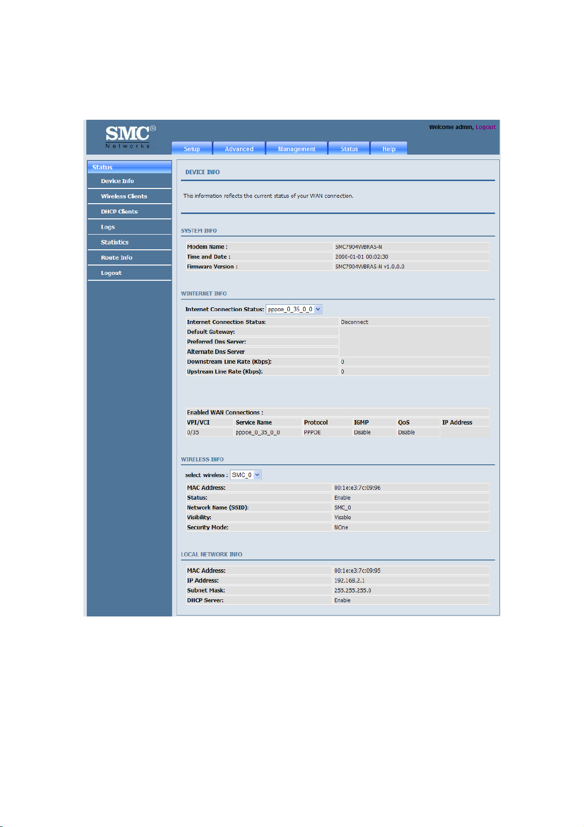
3.5.1 Device Information
Choose Status > Device Info. The page as shown in the following figure appears:
The page displays the summary of the device status, including the system information, WAN connection
information, wireless information, and local network information.
64
Page 81

3.5.2 Wireless Clients
Choose Status > Wireless Clients. The page as shown in the following page appears:
The page displays authenticated wireless stations and their statuses.
3.5.3 DHCP Clients
Choose Status > DHCP Clients. The page as shown in the following page appears:
This page displays all client devices that obtain IP addresses from the device. You can view the host name, IP
address, MAC address, and expiration time of the IP address.
65
Page 82

3.5.4 Logs
Choose Status > Logs. The page as shown in the following figure appears:
This page displays the system log. Click Refresh to refresh the system log shown in the box.
3.5.5 Statistics
Choose Status > Statistics. The page as shown in the following figure appears:
66
Page 83

This page displays the statistics information of the network and data transmission. The information helps
technicians to identify whether the device is functioning properly. The information does not affect the functions of
the device.
3.5.6 Route information
Choose Status > Route Info. The page as shown in the following figure appears:
The table displays destination routes commonly accessed by the network.
3.5.7 Logout
Choose Status > Logout. The page as shown in the following figure appears:
Click Logout to log out of the configuration page.
67
Page 84

Appendix A
Technical Specifications
Hardware Interface
-1 x RJ-11 WAN Port
-4 x RJ-45 Fast Ethernet LAN Ports
- Button: WPS, Wireless, Reset and Power
- 1 external 2dBi antennas
ADSL Standard
-ITU G.992.1 (G.dmt)
-ITU G.992.2 (G.lite)
-ITU G.994.1 (G.hs)
-ITU G.992.3 (ADSL2)
-ITU G.992.5 (ADSL2+)
-Annex L (reach extended ADSL2)
-ANSI T1.413 Issue 2
Protocols
-RFC2648/RFC1483/RFC2516/RFC1662/RFC1332/RFC895/RFC1042/RFC768/RFC791/RFC792/RF
C793/RFC862
-Supports ATM Forum UNI 3.1/4.0 PVC
- Supports UBR, CBR, and rt-VBR and nrt-VBR service classes
Wireless LAN Standard
-IEEE 802.11b, IEEE 802.11g, IEEE 802.11n
Security
-NAT/NAPT
-64/128-bit Wired Equivalent Privacy (WEP)
data encryption
-Wi-Fi Protected Access (WPA, WPA2)
-Anti DoS
-DMZ
Key Features
-DHCP Server
- ALG
-VLAN
-DNS agent
-QoS
-UPnP
-IGMP Snooping
68
Page 85

Appendix B
GPL Announcement
GNU GENERAL PUBLIC LICENSE
Version 2, June 1991
Copyright (C) 1989, 1991 Free Software Foundation, Inc.,
51 Franklin Street, Fifth Floor, Boston, MA 02110-1301 USA
Everyone is permitted to copy and distribute verbatim copies of this license document, but changing it
is not allowed.
Preamble
The licenses for most software are designed to take away your freedom to share and change it. By
contrast, the GNU General Public License is intended to guarantee your freedom to share and change
free software--to make sure the software is free for all its users. This General Public License applies to
most of the Free Software Foundation's software and to any other program whose authors commit to
Using it. (Some other Free Software Foundation software is covered by the GNU Lesser General
Public License instead.) You can apply it to your programs, too.
When we speak of free software, we are referring to freedom, not price. Our General Public Licenses
are designed to make sure that you have the freedom to distribute copies of free software (and charge
for this service if you wish), that you receive source code or can get it if you want it, that you can
change the software or use pieces of it in new free programs; and that you know you can do these
things.
To protect your rights, we need to make restrictions that forbid anyone to deny you these rights or to
ask you to surrender the rights. These restrictions translate to certain responsibilities for you if you
Distribute copies of the software, or if you modify it.
For example, if you distribute copies of such a program, whether gratis or for a fee, you must give the
recipients all the rights that you have. You must make sure that they, too, receive or can get the
Source code. And you must show them these terms so they know their rights.
We protect your rights with two steps: (1) copyright the software, and (2) offer you this license which
gives you legal permission to copy, distribute and/or modify the software.
Also, for each author's protection and ours, we want to make certain that everyone understands that
there is no warranty for this free software. If the software is modified by someone else and passed on,
we want its recipients to know that what they have is not the original, so that any problems introduced
by others will not reflect on the original authors' reputations.
Finally, any free program is threatened constantly by software patents. We wish to avoid the danger
that redistributors of a free program will individually obtain patent licenses, in effect making the
Program proprietary. To prevent this, we have made it clear that any patent must be licensed for
everyone's free use or not licensed at all.
69
Page 86

The precise terms and conditions for copying, distribution and modification follow.
GNU GENERAL PUBLIC LICENSE
TERMS AND CONDITIONS FOR COPYING, DISTRIBUTION AND MODIFICATION
0. This License applies to any program or other work which contains a notice placed by the copyright
holder saying it may be distributed under the terms of this General Public License. The "Program",
below, refers to any such program or work, and a "work based on the Program" means either the
Program or any derivative work under copyright law: that is to say, a work containing the Program or a
portion of it, either verbatim or with modifications and/or translated into another language.
(Hereinafter, translation is included without limitation in the term "modification".) Each licensee is
addressed as "you".
Activities other than copying, distribution and modification are not covered by this License; they are
outside its scope. The act of running the Program is not restricted, and the output from the Program is
covered only if its contents constitute a work based on the Program (independent of having been made
by running the Program). Whether that is true depends on what the Program does.
1. You may copy and distribute verbatim copies of the Program's source code as you receive it, in any
medium, provided that you conspicuously and appropriately publish on each copy an appropriate
copyright notice and disclaimer of warranty; keep intact all the notices that refer to this License and to
the absence of any warranty; and give any other recipients of the Program a copy of this License along
with the Program.
You may charge a fee for the physical act of transferring a copy, and you may at your option offer
warranty protection in exchange for a fee.
2. You may modify your copy or copies of the Program or any portion of it, thus forming a work based
on the Program, and copy and distribute such modifications or work under the terms of Section 1
Above, provided that you also meet all of these conditions:
a) You must cause the modified files to carry prominent notices stating that you changed the files and
the date of any change.
b) You must cause any work that you distribute or publish, that in whole or in part contains or is
derived from the Program or any part thereof, to be licensed as a whole at no charge to all third parties
under the terms of this License.
c) If the modified program normally reads commands interactively when run, you must cause it, when
started running for such interactive use in the most ordinary way, to print or display an announcement
including an appropriate copyright notice and a notice that there is no warranty (or else, saying that
you provide a warranty) and that users may redistribute the program under these conditions, and telling
the user how to view a copy of this License. (Exception: if the Program itself is interactive but does not
normally print such an announcement, your work based on the Program is not required to print an
announcement.)
70
Page 87

These requirements apply to the modified work as a whole. If identifiable sections of that work are not
derived from the Program, and can be reasonably considered independent and separate works in
themselves, then this License, and its terms, does not apply to those sections when you distribute them
as separate works. But when you distribute the same sections as part of a whole which is a work based
on the Program, the distribution of the whole must be on the terms of this License, whose permissions
for other licensees extend to the entire whole, and thus to each and every part regardless of who wrote
it.
Thus, it is not the intent of this section to claim rights or contest your rights to work written entirely by
you; rather, the intent is to exercise the right to control the distribution of derivative or collective
works based on the Program.
In addition, mere aggregation of another work not based on the Program with the Program (or with a
work based on the Program) on a volume of a storage or distribution medium does not bring the other
work under the scope of this License.
3. You may copy and distribute the Program (or a work based on it, under Section 2) in object code or
executable form under the terms of Sections 1 and 2 above provided that you also do one of the
following:
a) Accompany it with the complete corresponding machine-readable source code, which must be
distributed under the terms of Sections 1 and 2 above on a medium customarily used for software
interchange; or,
b) Accompany it with a written offer, valid for at least three years, to give any third party, for a charge
no more than your cost of physically performing source distribution, a complete machine-readable
copy of the corresponding source code, to be distributed under the terms of Sections 1 and 2 above on
a medium customarily used for software interchange; or,
c) Accompany it with the information you received as to the offer to distribute corresponding source
code. (This alternative is allowed only for noncommercial distribution and only if you received the
program in objects code or executable form with such an offer, in accord with Subsection b above.)
The source code for a work means the preferred form of the work for making modifications to it. For
an executable work, complete source code means all the source code for all modules it contains, plus
any associated interface definition files, plus the scripts used to control compilation and installation of
the executable. However, as a special exception, the source code distributed need not include anything
that is normally distributed (in either source or binary form) with the major components (compiler,
kernel, and so on) of the operating system on which the executable runs, unless that component itself
accompanies the executable.
If distribution of executable or object code is made by offering access to copy from a designated place,
then offering equivalent access to copy the source code from the same place counts as distribution of
the source code, even though third parties are not compelled to copy the source along with the object
code.
71
Page 88

4. You may not copy, modify, sublicense, or distribute the Program except as expressly provided under
this License. Any attempt otherwise to copy, modify, sublicense or distribute the Program is void, and
will automatically terminate your rights under this License. However, parties who have received
copies, or rights, from you under this License will not have their licenses terminated so long as such
parties remain in full compliance.
5. You are not required to accept this License, since you have not signed it. However, nothing else
grants you permission to modify or distribute the Program or its derivative works. These actions are
prohibited by law if you do not accept this License. Therefore, by modifying or distributing the
Program (or any work based on the Program), you indicate your acceptance of this License to do so,
and all its terms and conditions for copying, distributing or modifying the Program or works based on
it.
6. Each time you redistribute the Program (or any work based on the Program), the recipient
automatically receives a license from the original licensor to copy, distribute or modify the Program
subject to these terms and conditions. You may not impose any further restrictions on the recipients'
exercise of the rights granted herein. You are not responsible for enforcing compliance by third parties
to this License.
7. If, as a consequence of a court judgment or allegation of patent infringement or for any other reason
(not limited to patent issues), conditions are imposed on you (whether by court order, agreement or
otherwise) that contradict the conditions of this License, they do not excuse you from the conditions of
this License. If you cannot distribute so as to satisfy simultaneously your obligations under this
License and any other pertinent obligations, then as a consequence you may not distribute the Program
at all. For example, if a patent license would not permit royalty-free redistribution of the Program by
all those who receive copies directly or indirectly through you, then the only way you could satisfy
both it and this License would be to refrain entirely from distribution of the Program.
If any portion of this section is held invalid or unenforceable under any particular circumstance, the
balance of the section is intended to apply and the section as a whole is intended to apply in other
circumstances.
It is not the purpose of this section to induce you to infringe any patents or other property right claims
or to contest validity of any such claims; this section has the sole purpose of protecting the integrity of
the free software distribution system, which is implemented by public license practices. Many people
have made generous contributions to the wide range of software distributed through that system in
reliance on consistent application of that system; it is up to the author/donor to decide if he or she is
willing to distribute software through any other system and a licensee cannot impose that choice.
This section is intended to make thoroughly clear what is believed to be a consequence of the rest of
this License.
8. If the distribution and/or use of the Program are restricted in certain countries either by patents or by
copyrighted interfaces, the original copyright holder who places the Program under this License may
add an explicit geographical distribution limitation excluding those countries, so that distribution is
permitted only in or among countries not thus excluded. In such case, this License incorporates the
72
Page 89

limitation as if written in the body of this License.
9. The Free Software Foundation may publish revised and/or new versions of the General Public
License from time to time. Such new versions will be similar in spirit to the present version, but may
differ in detail to address new problems or concerns.
Each version is given a distinguishing version number. If the Program specifies a version number of
this License which applies to it and "any later version", you have the option of following the terms and
conditions either of that version or of any later version published by the Free Software Foundation. If
the Program does not specify a version number of this License, you may choose any version ever
published by the Free Software Foundation.
10. If you wish to incorporate parts of the Program into other free programs whose distribution
conditions are different, write to the author to ask for permission. For software which is copyrighted by
the Free Software Foundation, write to the Free Software Foundation; we sometimes make exceptions
for this. Our decision will be guided by the two goals of preserving the free status of all derivatives of
our free software and of promoting the sharing and reuse of software generally.
NO WARRANTY
11. BECAUSE THE PROGRAM IS LICENSED FREE OF CHARGE, THERE IS NO WARRANTY
FOR THE PROGRAM, TO THE EXTENT PERMITTED BY APPLICABLE LAW. EXCEPT WHEN
OTHERWISE STATED IN WRITING THE COPYRIGHT HOLDERS AND/OR OTHER PARTIES
PROVIDE THE PROGRAM "AS IS" WITHOUT WARRANTY OF ANY KIND, EITHER EXPRESSED
OR IMPLIED, INCLUDING, BUT NOT LIMITED TO, THE IMPLIED WARRANTIES OF
MERCHANTABILITY AND FITNESS FOR A PARTICULAR PURPOSE. THE ENTIRE RISK AS
TO THE QUALITY AND PERFORMANCE OF THE PROGRAM IS WITH YOU. SHOULD THE
PROGRAM PROVE DEFECTIVE, YOU ASSUME THE COST OF ALL NECESSARY SERVICING,
73
Page 90

REPAIR OR CORRECTION.
12. IN NO EVENT UNLESS REQUIRED BY APPLICABLE LAW OR AGREED TO IN WRITING
WILL ANY COPYRIGHT HOLDER, OR ANY OTHER PARTY WHO MAY MODIFY AND/OR
REDISTRIBUTE THE PROGRAM AS PERMITTED ABOVE, BE LIABLE TO YOU FOR DAMAGES,
INCLUDING ANY GENERAL, SPECIAL, INCIDENTAL OR CONSEQUENTIAL DAMAGES
ARISING
OUT OF THE USE OR INABILITY TO USE THE PROGRAM (INCLUDING BUT NOT LIMITED
TO LOSS OF DATA OR DATA BEING RENDERED INACCURATE OR LOSSES SUSTAINED BY
YOU OR THIRD PARTIES OR A FAILURE OF THE PROGRAM TO OPERATE WITH ANY OTHER
PROGRAMS), EVEN IF SUCH HOLDER OR OTHER PARTY HAS BEEN ADVISED OF THE
POSSIBILITY OF SUCH DAMAGES.
END OF TERMS AND CONDITIONS
How to Apply These Terms to Your New Programs
If you develop a new program, and you want it to be of the greatest possible use to the public, the best
way to achieve this is to make it free software which everyone can redistribute and change under these
terms.
To do so, attach the following notices to the program. It is safest to attach them to the start of each
source file to most effectively convey the exclusion of warranty; and each file should have at least the
"copyright" line and a pointer to where the full notice is found.
<one line to give the program's name and a brief idea of what it does.> Copyright (C) <year> <name of
author>
This program is free software; you can redistribute it and/or modify it under the terms of the GNU
General Public License as published by the Free Software Foundation; either version 2 of the License,
or (at your option) any later version.
This program is distributed in the hope that it will be useful, but
WITHOUT ANY WARRANTY;
without even the implied warranty of MERCHANTABILITY or FITNESS FOR A PARTICULAR
PURPOSE.
See the GNU General Public License for more details.
You should have received a copy of the GNU General Public License along with this program; if not, write
to the Free Software Foundation, Inc., 51 Franklin Street, Fifth Floor, Boston, MA 02110-1301 USA.
Also add information on how to contact you by electronic and paper mail.
If the program is interactive, make it output a short notice like this when it starts in an interactive mode:
Gnomovision version 69, Copyright (C) year name of author
Gnomovision comes with ABSOLUTELY NO WARRANTY; for details type `show w'.
This is free software, and you are welcome to redistribute it under certain conditions; type `show c' for
details.
74
Page 91

The hypothetical commands `show w' and `show c' should show the appropriate parts of the General
Public License. Of course, the commands you use may be called something other than `show w' and
`show c'; they could even be mouse-clicks or menu items--whatever suits your program.
You should also get your employer (if you work as a programmer) or your school, if any, to sign a
"copyright disclaimer" for the program, if necessary. Here is a sample; alter the names:
Yoyodyne, Inc., hereby disclaims all copyright interest in the program
`Gnomovision' (which makes passes at compilers) written by James Hacker.
<signature of Ty Coon>, 1 April 1989 Ty Coon, President of Vice
This General Public License does not permit incorporating your program into proprietary programs. If
your program is a subroutine library, you may consider it more useful to permit linking proprietary
applications with the library. If this is what you want to do, use the GNU Lesser General Public
License instead of this License.
75
Page 92

SMC7904WBRAS-N
 Loading...